
|
|
Forum Index : Solar : Simplified Solar Hot Water
| Author | Message | ||||
| Murphy's friend Guru Joined: 04/10/2019 Location: AustraliaPosts: 674 |
Hmmm, have another look at the schematic I posted at the thread above. You'll find that there is NO soldering/ unsoldering of resistors required. Instead, two trim pots are adjusted to set the trip points. To recap the requirements; use a water heating element that matches the medium solar panel string voltage AND power. Use an adjustable DC power supply instead of the solar input to set the trip points. I used a makeshift arrangement of rectified mains voltage and capacitors, the mains voltage being adjustable with a variac. This is much easier than trying to use the solar input to adjust this project. Have a read of my post to check how it's done. It's your choice if you wish to complicate a simple project with more electronics but I can guarantee you that there will be no magic increase of water heating power. |
||||
| Davo99 Guru Joined: 03/06/2019 Location: AustraliaPosts: 1585 |
I always felt bad that I could never get this going being that Tony designed it mainly to help me out. Don't like to waste peoples time when they are good enough to do something for me which seems like it wasn't appreciated which was the complete opposite. Simple as it is, was too much for me to figure out and felt I let Tony down. I can say that I learned a lot from this though. As perhaps inappropriate as it may sound, I'm glad others that are well ahead of me also had trouble with it. Obviously more to it than meets the eye. I did a couple of variations on the principle which Tony and I discussed. The first one was using an arduino with a modified "Blink" sketch to just pulse the MOSFET. I realised that the timing was not really important nor was the voltage levels. As long as the panels weren't dragged off their VMP or at least more than 10 % off it, the rest was pretty small potatoes. Also Realised as long as the caps weren't allowed to get Full and therefor waste solar power, voltage and timing wasn't real critical either. I played around with the timings for the cap bank by putting a 500W halogen light as the load. I could see the circuit simple as it was did work because I got next to nothing with a direct connection and an actual amount of useful light when I connected the pulse Circuit. I played with the timings on and off till I got the lamp to glow the brightest in good sun and then went a bit higher which had no effect which was allowing margin but more importantly, it worked great in the rising and falling light. And that was it. The thing runs all the time, initially from a small USB power bank thing which lasted days anyway. For simplicity I ended up solar powering it with just a big fat cap same as I used for the main storage as bit of a battery with a voltage controller. . Always felt that using an arduino was a waste so I bought a pre-built timer that went down to Hz for $12 I think it was and used that as the driver instead. Had the advantage of being able to ajust timings easier although I used the ones from the arduino and that was it. All it does is turn the fet on and off and that's all that's needed. The caps pose virtually zero impedence on the panels so they work efficently. The power in the caps does not really matter as long as they don't fully charge and leave no more room for the power the panels are generating. Even if they are 1/20th Full, all the power gets dumped into the load so there is no more loss than if they were 98% full. The aim of the game is not to drag the panels to 7V or whatever where they become highly inefficent and keep them in their happy place. This very crude and basic setup seems to do that. Also don't matter what size the cap bank is. You just run a higher frequency to dump the load faster. I have a pretty decent cap bank to allow for plenty of panels at slower timing ( around 50Hz I use ) and I don't even feel the FET getting hot. I would have liked to get this circuit working but it was beyond me but it did give me a more through understanding of what needed to be done to make the idea work and it seems my even more simplified soloution works just fine. I am also now looking to use the very same Circuit as a Battery Desulphator. They just pulse the power into a battery prefrably at high amps and voltage and this self same circuit is perfect for that. Even if I slow it down enough to get a full hit every time and loose some power, so what? It's the electric Vibration I basicaly want and this fits the bill perfectly. |
||||
| azhaque Senior Member Joined: 21/02/2017 Location: PakistanPosts: 131 |
Agreed 100%. As long as the circuit can 'PWM' the mosfets to keep them at the Max PP, all should be well. This can easily be done with a 555 with variable duty cycle. I am also prototyping the pvdirect water heater using the same concept that you have used. Initially however I am not even going to pulse it, letting the load draw the power. Infact the main problem is not the PWM freq or others but how to match the available solar panels to the existing mains designed water heater resistance, for max power point. 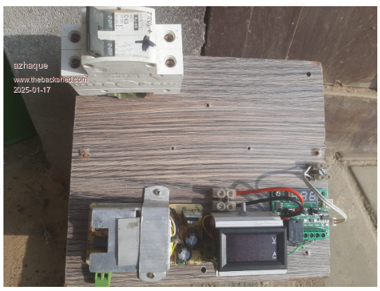 Here is a photo of breadboarded prototype. Top left is the breaker. Below it is the clamped down 12v isolated power supply. Next to it is a cheap DC ammeter-voltmeter. The voltmeter is only rated 100VDC so I cannot risk putting it to 240VC coming from my panels. Current measuring capability 10AMPS. My panels have an I-MPP of 8 Amps so this should work. It uses a shunt to measure the current making it suitable for low side measurement by connecting it between GND and the mosfet SOURCE(S). The MOSFETs (IRFP460)are mounted on an ALUMINIUM heatsink, go in the space visible between the Breaker and the lower row of instruments. These are soldered to a TO247 based PCB for a square wave UPS of yesteryear. Half of the PCB has be used. The other half is for my other geyser. A fan will be mounted next to the Breaker, and will blow onto the heatsink. Finally on the extreme right on the Breadboard the famous W1209 temp controller is visible. The acts as the thermostat by connecting/disconnecting 12 VDC to the MOSFET gates. Also conveniently displays the hot water temp. 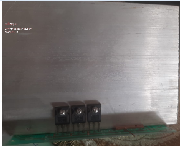 Agreed. However the main solar-time wasted isn't what you have mentioned. It would infact be the period when the water temp rises to the set point and the circuit remains off. This could vary from minutes to hours depending upon consumption/heat leakage from the geyser. The on-off cycle time is insignificant in comparison . Also true. When the mosfets are not conducting, the panels are charging the caps. When they are conducting panel current PLUS capacitor current goes to the load. I'll use a power coming from the panels as the power supply can take upto 250Volts. It is designed for mains use and therefore should have no qualms about powering from a 250VDC solar array. Another advantage is that it can be connected to the AC mains supply and thus keep the circuit and temp display running all the time. Good idea. $12 is too much for this  . I'll use a veroboard mounted 555 circuit which should cost less than $0 since I have all the parts available . I'll use a veroboard mounted 555 circuit which should cost less than $0 since I have all the parts available  . .In my case the W1209 will perform that function. I don't think even the 555 would be needed. As I submitted above, wasted panel-power is the power not consumed when the water temp is at its setpoint. Crucial point. Matching up V-MPP to the existing resistance of the hot water geyser is the main issue. Here is a pic of my dummy load using a 2KW electric heater element. It sagged when I connected it directly to the 240VDC solar array. Therefore the heat insulating tile. 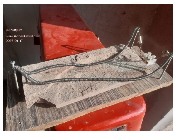 Proof of the pudding is in eating it. I disagree that the size of the cap-bank doesn't matter. It may not do so technically but it certainly does $$$$. As the Egyptian President of the not so recent past said and I quote. SIZE DOES MATTER. This I learnt from your thread about this topic. I was going to use Tony's circuit but then I saw your idea and now I am prototyping this one. Azhaque Edited 2025-01-17 16:07 by azhaque |
||||
| azhaque Senior Member Joined: 21/02/2017 Location: PakistanPosts: 131 |
Hi all, Managed to make some progress. 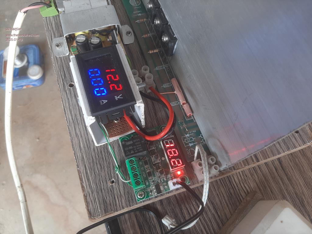 Only the fan remains to be installed after which it can be put to test. Sky is unusually overcast and a cold north wind is blowing. The panels are unable to even charge the batteries fully. Weatherman says that it will clear up tomorrow. Let's see. Azhaque |
||||
| azhaque Senior Member Joined: 21/02/2017 Location: PakistanPosts: 131 |
Video of the first test at low voltage 24vdc, here Sky remains overcast with light drizzle. Hopefully full voltage test tomorrow. Azhaque Edited 2025-01-20 21:02 by azhaque |
||||
| azhaque Senior Member Joined: 21/02/2017 Location: PakistanPosts: 131 |
The sun is back enabling further testing. Low Voltage High current test High Voltage Low Current test Panel VOC test with lamp load If the sun permits I'll connect the full 2kw load tomorrow to measure mosfet temp rise etc. Fingers xed. Azhaque |
||||
Revlac Guru Joined: 31/12/2016 Location: AustraliaPosts: 1257 |
The weather will do that when you want to test either a wind turbine or solar it will do that for a few days,  looks good. looks good. Cheers Aaron Off The Grid |
||||
| azhaque Senior Member Joined: 21/02/2017 Location: PakistanPosts: 131 |
|
||||
| azhaque Senior Member Joined: 21/02/2017 Location: PakistanPosts: 131 |
Latest Video of test Hi. Managed to get the cheap voltammeter working for my hot water system. The only downside is that the displayed voltage is about one third of the actual volts coming from the panels. Requires me to multiply the displayed voltage by 2.7, to get the actual volts. Small price to pay since the ever handy mobile phone lets me do that without any mental gymnastics. The good part is that the current is now being displayed. Both these values will help to show the power going to the water heater plus whether the system is working close to mpp. Shall connect and do a live test and maybe even take a shower with the solar heated water, to check the pudding. Azhaque Edited 2025-01-27 17:24 by azhaque |
||||
| Revlac Guru Joined: 31/12/2016 Location: AustraliaPosts: 1257 |
I think the volt meter might have voltage adjustment underneath the back cover on the PCB, voltage Reading might be averaged. Cheers Aaron Off The Grid |
||||
| azhaque Senior Member Joined: 21/02/2017 Location: PakistanPosts: 131 |
There is one. However its a 20K pot in series with a 270K resistor. So at best the pot can tweak but cannot change from 100vdc fsd to 250vdc fsd. I added a 470K resistor to do that. However the price is the multiplication factor of 2.7. I had thought of reprogramming the uncontroller which is an STM8. But on second thought the path is a potential can of worms which could brick it and distract me from the hot water project. So deffered for a future date. Azhaque Edited 2025-01-28 01:13 by azhaque |
||||
| azhaque Senior Member Joined: 21/02/2017 Location: PakistanPosts: 131 |
Partially Successful Test Video This test validated the Voltage measurement by the VoltAmmeter. As against that the current measurement was not OK and will require further investigation and testing. The temperature rise of the mosfets was negligible. I believe these can be safely reduced to 2 instead of 3 that are currently in place. Overall I believe I am on the right track. Will install when I have the current measurement kink, ironed out. Azhaque |
||||
| azhaque Senior Member Joined: 21/02/2017 Location: PakistanPosts: 131 |
DSN-VC288 Hack for Accurate Current display As reported earlier there was a substantial variation between the actual current flowing and the current displayed by the DSN. This has now been rectified by changing the gain of the LM358 used in the current measurement subsystem of the DSN. An 8.2K smd resistor was removed and wires soldered in its place. The wires were connected to a 100K pot since this is what was at hand and the needed value was between 10-15K. The result was fairly accurate. Later on I intend to replace the pot with a multi turn variable. Now to connect it to the water heater and see the results. Please stay tuned. Azhaque |
||||
| azhaque Senior Member Joined: 21/02/2017 Location: PakistanPosts: 131 |
Hi all, The system was installed today after making all the connections. Solar power from the panels began to flow at around 12:05 noon. Water temp in the tank was 15 degC. Approximately 1-1.2 kw of power was delivered to the water heater in the next 25 minutes or so which raised the water temp to 50 degC. The thermostat shut off the power thereafter. Test Video below. Live Test Video The pic below shows the water temperature having risen to 50 degC. The mosfets are off as can be seen in the pic below with current down to 0.0. Water temperature can be seen on the left blue display. 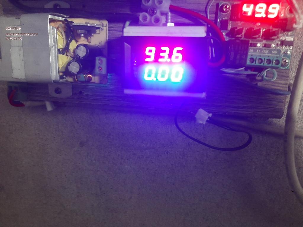 Will keep testing to achieve reliable operation. Azhaque |
||||
| The Back Shed's forum code is written, and hosted, in Australia. | © JAQ Software 2026 |
