
|
|
Forum Index : Solar : Solar Component Hackery.
| Page 1 of 4 |
|||||
| Author | Message | ||||
| Davo99 Guru Joined: 03/06/2019 Location: AustraliaPosts: 1585 |
I have looked at all the info I can find on direct water heating with solar. Everything I have seen is eitehr over my head and would take years of learning to build or it just plain does not do what I need. Most things are Low voltage, low wattage that is pretty much tiddly winks for what I want. I have been trying to learn here though but would really like some help and guidance to see if I can cobble something together using pre made boards and Minimal electronic design. I have come up with a no doubt flawed Idea which I think with a bit of help I could manage and satisfy this gnawing feeling I want to be able to do this. the basis for this ignorant idea would be one of these boards: https://www.ebay.com.au/itm/5A-MPPT-Solar-Panel-Controller-Constant-Current-Voltage-Step-down-Power-Module/283456838353? hash=item41ff581ad1:g:HxIAAOSwCyVcuYyt  It is capeable of handling 5A @ up to 36V. What I would like to do is hook 8 250W panels to the thing and have a relative output of say around 1.5KW which the panels should be able to provide in good light and get what I can on the ramp up and down. Although well beyond the capeabilities of this board I want to do some minor hackery to use it as the brains to drive other components that can handle the outputs I want just like I use a thermostat on a hot water heater to drive other components capeable of handling the DC currents without Frying itself first time it's powered. I have learned that I can use resistors as a voltage divider so can calculate ( with help) what I would need for the 8 30V panels ( working) to be sensed by the little 6-36V capeable board. I would feed the solar panel output to 6x 1000Uf 350V caps ( If I can manage to desolder them off the old inverter board!) to store the energy and give the 240V, 3600W element a full kick. I would have a mosfet handling the power to the element from the caps Driven by the output from the board which thanks to the resistors, should think it's handling a voltage within it's range. The Mosfet will do all the power switching and I think I'll need a small driver circuit to interface the switching and prevent the power going back and blowing the little board to soot and ash. The little Board should be able to keep the panels on power point giving some efficiency. Is this remotely Viable? I am not trying to charge batterys and divert excess, just something to keep tha panels on power point and producing the best power into the element they can. I don't care if it's overkill with the board or clunkyand could be done with less components from scratch, unless someone has something an idiot like me can build and understand or would be open to a paid job of building such a board, the requirement is -I- can build it and it does what I want. I have done a few things like this by cobbing different boards together just through wiring them and I'd like to be able to do the same with this far as possible. If it's not viable due to my extreme electronic Ignorance, fair enough, if it is possible, I'd greatly appreciate some help with the sub circuits. I am thinking I'll have to go with a DIY mosfet circuit as an SSR may not be able to be switched fast enough but If it could be with the help of a bleed resistor, so much better. The more prebuilt and just wired together I can make it, the better. If it costs $50 in boards that the knowledgeable could build for $5, so be it. the goal is ease of build and function not good circuit design and absolute low cost. :0) I think this is something a lot of people would be interested in IF there were something simple enough they could build without having to decipher pieces of a jigsaw breadcrumbed by others that will take years to understand. I'm surprised the Chinese haven't produced a board for this purpose, maybe they will in the future? I wonder what I would cost to commission one and have them made to sell? Anyway, any and all input on my idea of ignorant simplicity would be appreciated. |
||||
| Tinker Guru Joined: 07/11/2007 Location: AustraliaPosts: 1904 |
I do not know anything about what you are trying to do but have a hint how to get those caps easy off old inverter boards. First you have to carefully remove the 'blob' goo that they squirt in to hold the caps steady. Use a small screw driver to dig it out. Then I use a modified old soldering iron tip. Basically cut it short and tap a thread on it (M5). Then cut a bit of flat copper bar (10 x 3mm) to the distance between the cap pins. Tap the middle of this and screw to your modified soldering iron tip. You now have a T shaped tip You can use this to heat both pins at once quickly and pull the cap off the board at the same time. You need about 60W soldering iron power. Klaus |
||||
| Warpspeed Guru Joined: 09/08/2007 Location: AustraliaPosts: 4406 |
Yes it can be done, but a lot depends on exactly what you want it to do. If all you want is use solar panels for heating water and keep the panels operating around the most efficient power generating voltage, then that is not too difficult. Many people want to divert excess power into heating water, but only after the main function of recharging a battery has been achieved. That requires a much more complicated control strategy. Anyhow, the basic idea is to maintain the solar panel voltage within a fairly limited operating range, where they are operating close to their efficiency peak. The heating element is of course a fixed load, which will be far too much load for solar to drive, except under the most ideal conditions. The way to do this is to connect the solar panels to a large energy storage capacitor bank, preferably at a high dc voltage. The amount of energy stored in a capacitor is proportional to the voltage squared, so a higher voltage will require fewer and smaller capacitors and be more efficient. What we then do is connect our heating load to the capacitor bank through a mosfet switch so that the load can be switched on and off electronically. We have a voltage sensing circuit that switches the load in and out at two very distinct voltage levels of the capacitor bank. The capacitor storage bank charges up either very slowly under poor solar conditions, or much faster in more optimum solar conditions. But when the voltage reaches some set maximum, the heating load is switched in. The voltage on the capacitor bank will quickly fall, and when it reaches a set minimum, the mosfet switches off. So the voltage on the capacitor bank rises and falls between two fixed voltages, and those are set to coincide with the most efficient solar panel operating voltage range. The discharge time will be pretty much fixed by the stored energy and the resistance if the heating element. But the charging up time will be highly variable depending on how much solar current is available. It could be several milliamps to several amps. So the frequency at which the system cycles on and off will be highly variable from minutes to several or many tens of Hz. One problem to be aware of is that the thermostatic switch in the hot water storage tank, and the mandatory manually reset over temperature cutout, will arc heavily and quickly burn out if an attempt is made to supply straight dc to to the heating element. That problem can be overcome by using four mosfets in a bridge configuration instead of just one mosfet to switch power between the capacitor bank and the heating element. That will disrupt any arc that forms, similar to what happens with the ac mains supply. Its all fairly straightforward, and suitable voltage operating points and capacitor bank sizing can be worked out theoretically, or found experimentally. Cheers, �Tony. |
||||
| Solar Mike Guru Joined: 08/02/2015 Location: New ZealandPosts: 1204 |
Search the forum, his topic has been covered previously, PV Hot Water , unfortunately its unlikely off the shelf modules will work here, I certainly couldn't find anything suitable at the time. A circuit and pcb has been developed for the HWC system, but as yet not implemented, was going to use this in a property that I'm currently renovating, currently installing new HWC and replacing all plumbing pipes and fittings in the house, so will be returning to this project later in the year. Cheers Mike |
||||
| Davo99 Guru Joined: 03/06/2019 Location: AustraliaPosts: 1585 |
Unfortunately Mike you are playing with the lowest common denominator here and constructing that board would be way over my head. Wiring I am OK with, electronic circuit design/ building I am at kindergarten level. If you are going to build and sell a board I can just wire up i'd certainly be interested at least a few. I think there could be good sales potential for them on fleabay or the like. I am on a few different DIY type forums and this regularly comes up. The normal problem is exactly the same as I have, people want something to do this but there is no product available. I have seen the attitude by some of the knowledgeable that people should learn electronics in order to be able to build one for themselves so they can repair it if something goes wrong with it later. I find this a ridiculous notion. Did these same people build their own car? Their TV, all their Furniture, do the electrical wiring and plumbing in their house? By their own standards they preach to others they should have! What I want to do is akin to building my own computer which I have done Dozens of. I buy the board and the ram and the Hdd's Video card, case, KB, Mouse, Monitor and all the individual components and make them work together to do what I want. that may be a lightweight machine for net surfing, an over the top thing for gaming, a server and work stations for Business or something to control a process manufacturing line. I don't have to design every component, I buy the bits I need and put them together to do what I want. For myself and others, this is achievable where designing the Video card and building it would take a lifetime to come up with something inferior anyway. If you do a board you are prepared to sell, I and other would be very interested. |
||||
| Warpspeed Guru Joined: 09/08/2007 Location: AustraliaPosts: 4406 |
If you want it really simple, why not build a solar thermal system ? All you need are the solar heat panels and a standard hot water circulating pump, and some pipework. The control system and temperature sensors are all just a common commercially available items. Cheers, �Tony. |
||||
| Davo99 Guru Joined: 03/06/2019 Location: AustraliaPosts: 1585 |
Hi Tony, Thanks for the feedback. It seems I have the theory right in my head which is a win for me in itself. I am only interested in direct heating atm, no battery charging. This has been a problem that has ruled out several designs I have seen. They are overly complicated for me because they have added functions I don't need and just confuse the issue further. If you would be prepared to help me set this up I would be most grateful. I am aware of the DC switching Issue and have a solution to that however I would be interested in hearing how to do it with 4 mosfets. One way I do it now is with a small power supply through a mosfet or an SSR and just use the Thermostat as a low voltage, low amperage switch for the SSR or mosfet so the thermo has a load of Ma not the current of the element running through it. The questions I can think of off the top of my head: If I am using 8x 250w, 30V panels in series, what are the resistor Values i'm going to need to run the little board? If I was using 4 Panels instead, would the required resistance be half or quarter that of the 8 panels resistance? How do I drive the element from the boards output? Can this be done with a DC SSR or will I need to set up a circuit for switching mosfets? Are there any pre-made boards one can buy you are aware of that can do that? How would the mosfet switching circuit be set up for the element and what component values would I need for that? For the 8 Panel, 2kw Nominal input, what Value of caps would you recommend? I have 6 1000Uf, 350V units out of a solar inverter which I assume would be suitable. Would I be correct in thinking that the more capacitance one puts in, the slower the potential switching time due to the longer charge up? Could this switching rate be slowed enough ( at peak output when it will be fastest) to allow the use of an SSR? Is here anything else I have overlooked need to know? Thank you very much for your help and feedback. Muchly appreciated! |
||||
| Davo99 Guru Joined: 03/06/2019 Location: AustraliaPosts: 1585 |
I could do that and am more than capable but it's not the way I want to go. In effect, while I can do it, I think it's far more complicated running pipes and pumps and circuits etc. It would also be far more expensive. The other thing is, I want this to be able to be self sufficient in that I can put it up the back in a greenhouse with no electrical or water connection. It is only to heat a tank for thermal storage in that application and I think much easier to heat a tank with PV than direct with pumps etc. A very eco minded friend of mine had the Vac tube system and took it down and replaced it with PV. He is a scientist/ engineer so keeps precise details of everything and had a lot of Monitoring in place. He felt after a couple of years observation he was better off with extra PV and electrically heating. His position was on a cloudy day you got something with PV and nothing at all with Direct. Further more he said his tank could be up to temp by 10 am or earlier in summer with direct and the rest of the day it sat there wasted where as with PV he was getting some FIT and the panels were earning their keep. The other thing was he felt there were FAR few failure and trouble points with PV than there was with the Plumbing and pumps which I also agree with. Bottom line is I think we are both more comfortable with Power than water He uses a PLC to control the heater to come on during the day and only when there is a minimum level of power from the panels he set. If the tank is not up to the Min temp at 7PM, the tank switches to mains power to heat it till it is. For long periods of bad weather he can just switch back to the regular off peak but overall his savings have been better with the PV than the direct. For me wiring is much easier to integrate from my panels than doing all the plumbing which will cost more and I don't believe is as efficient over all for -MY- needs. I have seen Vids where they say they are as efficient as each other but for me, extra power especially in winter would be better if the tank did come up to temp. |
||||
| Warpspeed Guru Joined: 09/08/2007 Location: AustraliaPosts: 4406 |
I agree, that a solar thermal system can have problems with parasitic heat loss, and the potential for freezing damage. But its the sort of thing just about anyone can get working very quickly. A lot depends on the climate. A direct solar electric system has some advantages, but its not a common popular approach, and so just choosing an off the shelf solution is not really going to be possible. [quote]The questions I can think of off the top of my head: If I am using 8x 250w, 30V panels in series, what are the resistor Values i'm going to need to run the little board? If I was using 4 Panels instead, would the required resistance be half or quarter that of the 8 panels resistance? How do I drive the element from the boards output? Can this be done with a DC SSR or will I need to set up a circuit for switching mosfets? Are there any pre-made boards one can buy you are aware of that can do that? How would the mosfet switching circuit be set up for the element and what component values would I need for that? For the 8 Panel, 2kw Nominal input, what Value of caps would you recommend? I have 6 1000Uf, 350V units out of a solar inverter which I assume would be suitable. Would I be correct in thinking that the more capacitance one puts in, the slower the potential switching time due to the longer charge up? Could this switching rate be slowed enough ( at peak output when it will be fastest) to allow the use of an SSR? [/quote] I have never built one of these myself, but we can look at the whole problem from the theoretical aspect. I have a spare 24v panel here, and a means to test it, so tomorrow I will make some measurements of what sort of voltages we might expect at peak power and at what voltage the power falls away by either side of that peak. We are close to mid winter down here, so I need a reasonably cloudless sky to do this test which may be rather difficult. And yes, the larger the capacitor value the slower it will cycle. But there is another problem. We can only discharge some small proportion of the total stored energy. The voltage can only be allowed to fall so far to remain in the high efficiency area of the solar panels. So we cannot recover all of the stored energy, but only a small fraction. That means the total stored energy is going to be enormous to be able to transfer power at the kilowatt level. It may be impractically large (cost) but we shall see. The trick will be to find out what might be some suitable threshold voltages to keep the panels working efficiently, and how much capacitance might be required. I have no feel for this, so some practical testing will be required on which to base some assumptions. Can you tell me the voltage and power rating of your prospective heating element ? I may not be able to do anything tomorrow if its very cloudy, but we shall see. Cheers, �Tony. |
||||
| davef Guru Joined: 14/05/2006 Location: New ZealandPosts: 499 |
Tony, Last line ... do you mean over the first few on/off cycles? Hopefully, that lost initial first charge cycle energy becomes insignificant after 10-100 charge/discharge cycles. Dave |
||||
| Warpspeed Guru Joined: 09/08/2007 Location: AustraliaPosts: 4406 |
Suppose for example, (I really do not yet know) we can only discharge our capacitor by 10% of the total stored energy, until the voltage falls to the low voltage limit, and we have to recommence the next charging cycle. If we need to transfer 2Kw, then the capacitor bank may need 20Kw of accumulated charge to do that. And because it pulses, the peak energy transferred will need to be a lot higher than the average. If for example it charges up to 20Kw of stored energy, and then discharges down to 18Kw of stored energy each cycle. There is no problem with doing that technically, except the capacitor bank may need to be much larger and more expensive than we expect. I have no idea at this stage, which is why I need to take some measurements and work out some requirements and crunch some numbers. It will certainly work, but it may be a whole lot larger and more expensive to build than we anticipate. Or it may all turn out to be dead easy, I really do not know. Cheers, �Tony. |
||||
| Solar Mike Guru Joined: 08/02/2015 Location: New ZealandPosts: 1204 |
Another way of perhaps better utilizing the capacitor is have two, whilst one is being charged from the PV array, the other is discharged across the HWC element. When the cap voltage falls say 10v below the rated element voltage then the other one discharges... dia here shows concept, replace the switches with mosfets and have your arduino etc monitor the voltage on both cap's, switching the mosfets at the rate necessary to recharge them. 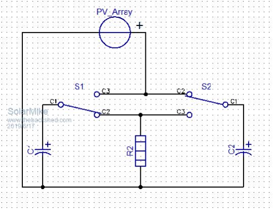 Cheers Mike |
||||
| Davo99 Guru Joined: 03/06/2019 Location: AustraliaPosts: 1585 |
Hi Tony, Thank you very much for looking into this for me. Very generous of you. The elements I want to use are 3600W, 240V, 15 Ohm from memory. The panels are 250W, 30V pmax, open circuit 37v. If doing 2 Kw is impractical, I'd like to know what you think would be more manageable. Mike, to the ignorant your idea sounds good. How would one switch such a circuit and with what components? |
||||
| Warpspeed Guru Joined: 09/08/2007 Location: AustraliaPosts: 4406 |
Dual capacitors definitely worth some serious consideration Mike. The capacitor value may turn out not to be that criticalas far as energy transfer goes. Smaller capacitor(s) just may mean it cycles much faster. Don't know, need some actual voltage and resistance numbers to play around with. If the discharge time is kept fairly short, say in the tens of millisecond range, and the load is then completely disconnected electronically for some relatively longer charging up period, the risk of having continuous arcing of the thermostat contacts may not be a problem after all. Another interesting feature of this, is that you don't just get current from the discharging capacitor, but the direct constant solar current as well during discharge. Lots of interesting twists and turns trying to think all this through. Cheers, �Tony. |
||||
| Solar Mike Guru Joined: 08/02/2015 Location: New ZealandPosts: 1204 |
Using a single mosfet switch: If the element draws 15 amps @240v = 3600w, and the panels mppt output = 8x30 = 240v @8.4amps, then yes the panel will also supply current simultaneously with the cap discharge, but will also voltage drop soon as the cap has discharged as current output cannot be sustained. The ratio of time discharge to re-charge will increase as the capacitor gets bigger; this off delay maybe enough to prevent arcing, could easily be calculated... Mike |
||||
| Warpspeed Guru Joined: 09/08/2007 Location: AustraliaPosts: 4406 |
Solar panels are always rated with insolation set at a standard 1Kw per square meter, but the sun cannot quite reach that, at least not at sea level. So we typically might recover only about 80% of rated output in a clear blue sky. A 250 watt panel might be expected to source only 200 watts of output at best, perhaps 6.67 amps at 30v. We should easily be able to transfer most of that. When the sun decides to show up, I can test a spare 200 watt mono crystaline panel I have sitting here, and test how the power falls away at voltages higher and lower than the peak power point. Its been very cloudy here in Melbourne in recent days , so will just have to wait for a patch of clear blue sky. I would like to establish some rough voltage set points. If we can switch where the power has reduced by say 10% either side of the the power peak, and we charge and discharge through the peak, it may be possible to transfer something like 95% average of full available output. Once we have some initial voltage set points we can see what the numbers are telling us. Cheers, �Tony. |
||||
LadyN Guru Joined: 26/01/2019 Location: United StatesPosts: 408 |
Here are my own observations: 1. over a large insolation range, the voltage stays the same but the current scales linearly 2. given similar insolation, lower the ambient temperature, higher (~10%) the voltage (similar current) = more power 3. load HAS to be matched to the panel, otherwise, the load will draw the panel down to a suboptimal power The last one needs a lot of thinking and is not trivial to deal with. It WILL mean the difference between gallons of water that is barely warm vs. hot enough for a few showers given the SAME amount of panels. DIRECT hookup of heating elements to PV Array will just not work unless you throw enough panels (= money at it). A more efficient solution will figure out a way to match the PV Array to load. My intuition is more can be done with less - for example, a suitably sized capacitor bank with a setpoint relay could pull it off. If that intuition's true: 1. What's a suitably sized capacitor bank? 2. What's a suitable setpoint? I expect to model this better to understand this but dont have time yet. |
||||
| Warpspeed Guru Joined: 09/08/2007 Location: AustraliaPosts: 4406 |
The voltage stays almost the same, such that we can use two set points to charge and discharge our capacitor over a very wide insolation range, and lose very little in the way of recoverable energy. Within reason, the capacitor bank size may not be that critical. It just has to cycle much faster with a smaller capacitor. How big a jug do you need to fill a bath ? Its totally grey sky with intermittent spitting rain here right now, so not really suitable for any useful testing. Cheers, �Tony. |
||||
radar Newbie Joined: 09/06/2019 Location: AustraliaPosts: 16 |
I am new here at the shed , I dont know if the picture ill upload would be relevant to this thread . But using some cheap/second hand parts might produce an answer that could be leggo'ed together with little pcb skills needed . That is if the ( Magic Thingy ) in the photo already exist's . 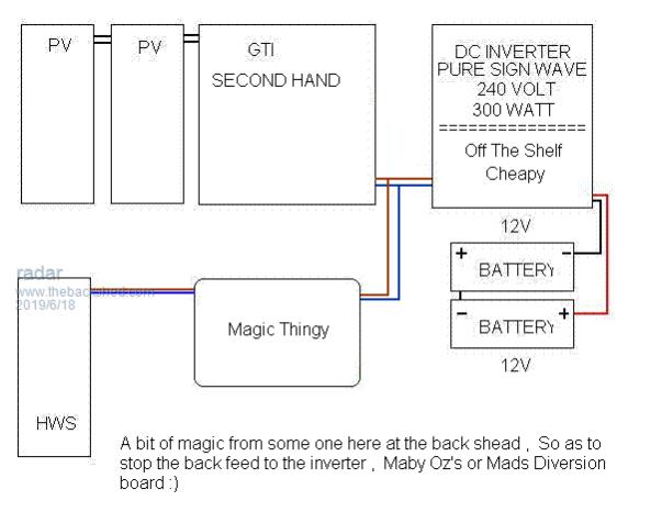 |
||||
| Solar Mike Guru Joined: 08/02/2015 Location: New ZealandPosts: 1204 |
As a thought experiment whilst Warp is waiting for some winter sun to do a practical test... looked at the basic theory and calculations required to estimate initial parameters. For a rough theory calculation using Davo99 data: 8 x 250w 30vmp 8.3a panels in series = 240v at 8.3 amps current. Use a good large 10,000uf 350v low esr capacitor. HWC element = 16r A mosfet will turn on, discharging the charged capacitor across the HWC element when its voltage reaches 240v and turn off when the cap voltage drops by approx 10%; whereon the panels charge it back to 240, if in full sun then at 8.3 amps, if less sun then will take longer. When a capacitor is discharged across a resistor (element) the rate of voltage drop is exponential, so its voltage drops very quickly and determind by the formula Vcap = Vsource x e^-t/RC, if we pick a 10% voltage drop for discharge trip point (turn off), plugging in the values, a 0.1RC time constant will drop the initial cap voltage from 240 to 216 in 16mSec So for approx 16ms the element is subjected to the full 15 amps from the discharging cap + the 8.3 amps from the panels, power is transferred to the element. Once the mosfet is turned off by some sort of voltage switch at 216 volts then the cap is charged up again at a linear constant rate 8.3a or whatever the panels can output at the time. Basic formula for constant current charging V=Q/C where Q=It, so V = It/C or t = VC/I, plugging in values t = 24 X 10,000/1000000/8.3 = 29mSec, so best case 29 ms to re-charge ready for the next discharge cycle. This 29ms recharge delay means if the thermostat opens at some point, the off period means any arc formed on opening will extinguish, hopefully... There will be losses doing this switching, looked at specs of a suitable mosfet IRFP4868, 70a, 300v, 32 mR, every discharge cycle of 15+8.3a at 16/29 duty cycle it will dissapate approx 10 watts worse case. However efficiency will be high. Capacitors have an esr, a good one (costs $$) will be approc 10mR, it will loose power on discharge 15a and recharge 8.3a, so its losses amount to 1.6 watts each cycle, rather than pay $70 for a good cap use 10 x 1000uf ones to get their combined esr down and surface area up, may be more cost effective. There is a certain amount of flexibility here in that the PVmp voltage can be somewhat higher than the element to cater for different panel voltages. On paper it looks promising, see what Warp comes up with. Concept circuit: 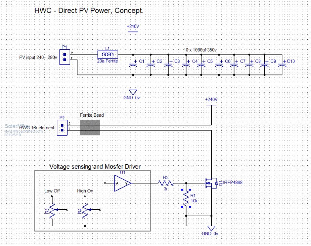 Radar, thanks for the input, not everyone will have a battery system for this, efficiency is lost with all those inverters... Cheers Mike |
||||
| Page 1 of 4 |
|||||
| The Back Shed's forum code is written, and hosted, in Australia. | © JAQ Software 2026 |
