
|
|
Forum Index : Solar : Experimental Multi-Phase Solar MPPT Controller
| Page 1 of 3 |
|||||
| Author | Message | ||||
| Solar Mike Guru Joined: 08/02/2015 Location: New ZealandPosts: 1204 |
I have always wanted to experiment building a multiple phase mppt charge controller, this is where multiple mppt sub controllers combine their outputs whilst being sourced from a common PV supply. Reason being, having multiple phases allows for smaller inductors and capacitors, lower currents in the buck converter and less losses. The design would allow for adding on extra phase stages as required, depending on how much power is wanted, ie modular. However each buck stage has to be semi-autonomous, with its own voltage and current control, so gets pretty complex very quickly. A multiple phase example would be say every 60 degrees a buck inverter completes its switch cycle, thus over a 360 degree period 6 cycles would occur from 6 combined buck stages. There are specialized chips out now as used in multi-phase mother board power supplies that do this and more, but they are very specialized, I want something more generic. My thoughts were to use an 8 pin PIC cpu in each buck converter or perhaps an ATTiny85, as I have lots of spare Picaxe 08M2 chips, thought that would be a good starting point. With this chip we can have 32Khz background PWM with 1024 bit resolution or higher pwm speeds but less resolution and a 32Mhz cpu clock speed. All the chip has to do is measure its output current and voltage, limiting the voltage to a master reference input whilst running an mppt algorithm. If I use say 5 buck circuits each limited to 30 amps, then only 2 mosfets are required in each, one for the buck stage, other for the synchronous rectifier. This gives a respectable potential of 150 amps @50vdc Āor 7.5KW output, all using small easily obtainable inductor cores. In comparison the other 3KW charge controller design at 100 odd amps output uses humongous cores that are only obtainable direct from the factory in the USA. However having multiple controllers with their own clocks etc does not give a true synchronous phase locked output, more like a random frequency and phase; which may work just as well. Here is the proposed design. 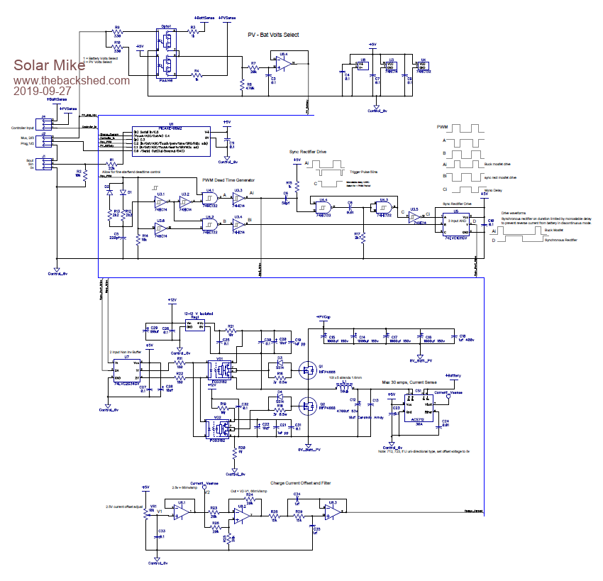 SlaveMppt.pdf The circuit here is a slave mppt controller that will be built on a smallish PCB, multiple pcb's can be stacked together to give the desired current output. A host controller of some sort will tell each slave what voltage and current to regulate to, along with the operation mode (bulk, equalize, float etc). However for testing the host isnt required initially as voltage set points can be code constants. Voltage sense is multiplexed to a single pin, current is measured by the commonly available Allegro ACS 712 or 723, single CPU PWM output is split up into non-overlapping buck and synchronous rectifier drive signals, the sync rect. especially has its on period limited by monostable timeout to prevent havoc caused by battery current back feed into the buck circuit during times of discontinuous operation. I attempted to breadboard some of this and gave up, rats nest of wires just doesn't work here; so will go straight to pcb. Am also testing the other 3KW mppt controller design, code is very similar, so will be interesting to compare both designs. Cheers Mike Edited 2019-09-27 21:17 by Solar Mike |
||||
| Warpspeed Guru Joined: 09/08/2007 Location: AustraliaPosts: 4406 |
Some interesting ideas there Mike, you seem to have covered the potential problems. Back feeding power at low duty cycles needs to be watched very closely, software should be able to handle that, although there is at least one "smart" active rectifier gate driver chip out there, but cannot now recall the type designation. Thinking about it, a random phase/frequency relationship between individual buck modules might produce a pretty lumpy current measurement as everything drifts in and out of synchronism. That should become less of a problem as the number of modules increase. I built something like this a very long time ago, but it was all strictly hardware. I used a twisted ring Johnson counter to generate multiple phase square waves. That was turned into a bunch of triangle waves by multiple rc integrators. Those went into multiple voltage comparators that each generated an 0% to 100% duty cycle output from a common dc control voltage. Lots of parts, but basically very simple. It used common voltage and current measurement, and separate PID control loops for voltage and current control in the usual way. Pretty happy with how it turned out, although I have never built another one since. Cheers, ĀTony. |
||||
| Solar Mike Guru Joined: 08/02/2015 Location: New ZealandPosts: 1204 |
Yes used those chips in the 3kw design, works well, just wanted to try something different this time using common off the shelf components. Yes they have a chaotic output, figured 5 or more would even things out. I did breadboard up a /10 counter driven by a PWM clocked input, each output was then ANDed with the original PWM to produce 10 PWMed phases, seemed to work, trouble the PWM frequency had to be 300 Khz or so, way beyond what any CPU could produce that I have here, so gave up on that idea. Perhaps if I used a fast 32bit cpu running assembly language, one could bit bang multiple synchronous phased PWM outputs, would certainly cut down on components, perhaps in the future, can anyone suggest a suitable chip... Cheers Mike |
||||
| Warpspeed Guru Joined: 09/08/2007 Location: AustraliaPosts: 4406 |
A different way to create multiple phases would be to start out with just one master pwm waveform, and delay that through a long shift register that is clocked at a very high frequency. Cheers, ĀTony. |
||||
| Solar Mike Guru Joined: 08/02/2015 Location: New ZealandPosts: 1204 |
Interesting idea, single CPU only required, it would have a lot of work to do managing everything.?? I have made a start on the PCB, realized needs some extra complexity to allow each slave unit to run standalone if required; have decided to use the higher current ACS723-40 current sensor (40A), the older cheap as chips ACS712-30 is no longer made nor recommended for new designs, but easier to get on AliExpress etc. Newer 723's have 1/2 the through resistance so less heat. Another mod is for each module, control its own PV Isolation Mosfet, I was going to have this on the Main Host board, normally multiple parallel devices, but it makes sense to place with each slave, also helps allow the slave be run as standalone. As these modules will have their own 40 fuse link joining to the common battery buss, there needs to be some mechanism to detect a blown fuse or perhaps the main battery breaker popping out, consequence of this event whilst under high charge is Buck voltages sudden dramatic increase to blow every thing up levels. Have opted for comparator sensing the voltage increase and turn on a clamp mosfet, placing a heavy load across the module, independent of CPU, this gives CPU time to shut everything down before its 5v rail dies and the perhaps sacrificial 5R power resistor going up in smoke. Connected to the last available pin on the PIC, serial input, can also be used as a Pull High input switch (detected by interrupt). 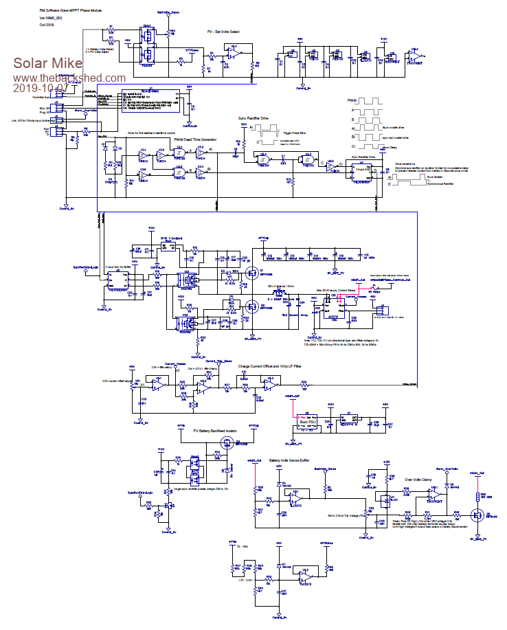 SlaveMppt_002.pdf Cheers Mike Edited 2019-10-08 06:06 by Solar Mike |
||||
| Solar Mike Guru Joined: 08/02/2015 Location: New ZealandPosts: 1204 |
I had a play with the Picaxe 28X2 chip to see how its HPWM Half Bridge mode worked. Running the cpu at 64 Mhz max PWM frequency is 62.5 Khz with 10bit resolution, in 1/2 bridge mode the dead time is easily set anywhere from 100 ns upwards. The smaller chip in the X2 range 20X2 would be the same; there would be many advantages in using the 20X2 chip in the slave mppt module, the circuitry can be simplified having greater IO pins to play with along with the 1/2 bridge mode PWM outputs and the higher PWM means the buck inductor is smaller. These CPU HPWM outputs have timing issues on cpu initialization and power off, however using Warps excellent method for connecting the opto couplers, these problems are avoided. Here is an amended simpler circuit using the 20X2, I am very tempted to now alter the PCB design to use the bigger cpu, even though it costs 3x as much. CPU connections not shown. I ordered 4 of them and they arrived today, only thing is idiots sent me the wrong chips, they sent the rather expensive 28X2 versions, yet their web store says that one isn't in stock??? 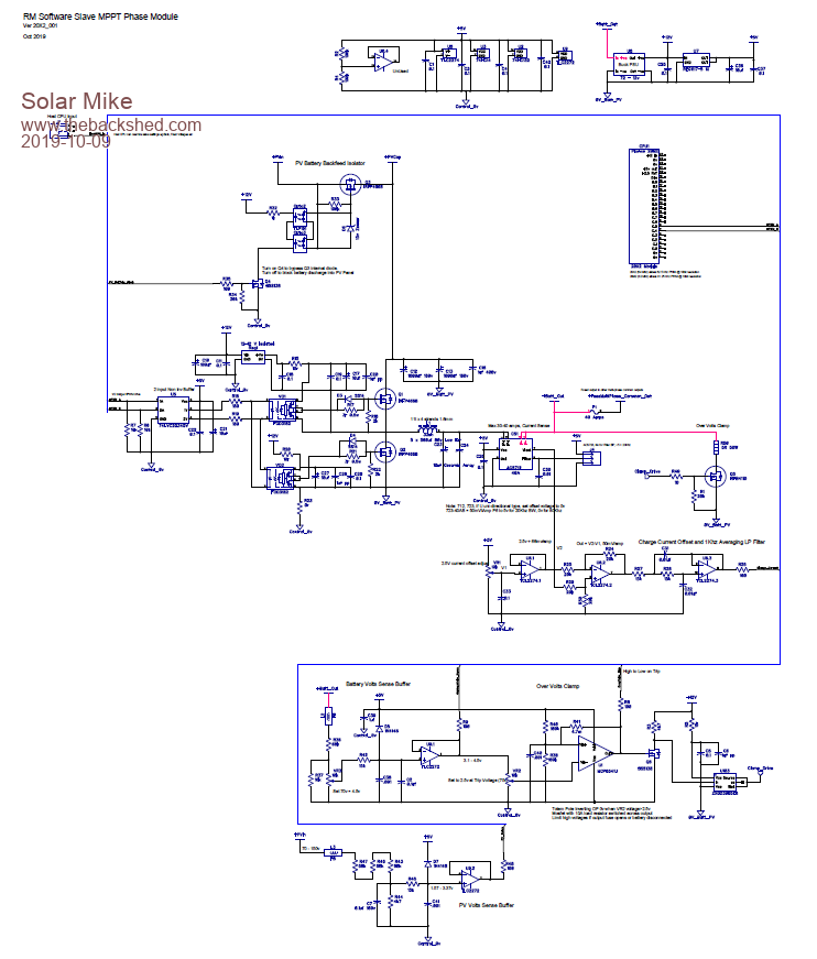 SlaveMppt_20X2.pdf Cheers Mike |
||||
| Solar Mike Guru Joined: 08/02/2015 Location: New ZealandPosts: 1204 |
Past few weeks in between renovating Āa house, have spent some more time on this project, after several iterations, changes in circuit design, a pcb has been laid out and will be sent to China for manufacture tomorrow. Final circuit uses a PICAxe 20X2 running at 64 Mhz, mounted on a plug in pcb as the brains, using its 1/2 bridge output mode to drive the buck converter and the synchronous rectifier, gave away the idea of using the mini 8 pin device, not enough IO's and too slow. Each mppt module is using a 40 amp current sensor chip, so would expect max output charge current be limited to less than that. This keeps the buck inductor to a reasonable size. Biggest change to the circuit is replacing the PV - Battery isolation mosfet with a small high power pcb relay, there are 2 variations on this, one using a 20A relay, the other is a 30 amp, pcb allows for either. The circuit also has a relay coil minimiser drive to reduce the coil dissipation should the larger relay be used. The use of a relay gives a more robust isolation than using a single mosfet. As the cpu has more IO, have made the most of available pins, the original idea was each mppt module acts as a slave device, having a master to control multiples connected on parallel; now by setting a link the module acts as a master and can control 4 other slaves, this will make it easier to test and setup. Also added are optional remote battery sense using a differential amp board, I2C outputs to an extra IO display, relay PCB and a serial LCD output. A lot of attention has been on the earthing and current paths, star earthing used with control and power 0v rails separated and joined in one place only. PCB also allows for different main capacitor combinations (sizes) as I will be testing for two PV voltages of 110v and 165V, max input voltage would be 200v due to 1.5mm pcb trace clearances. 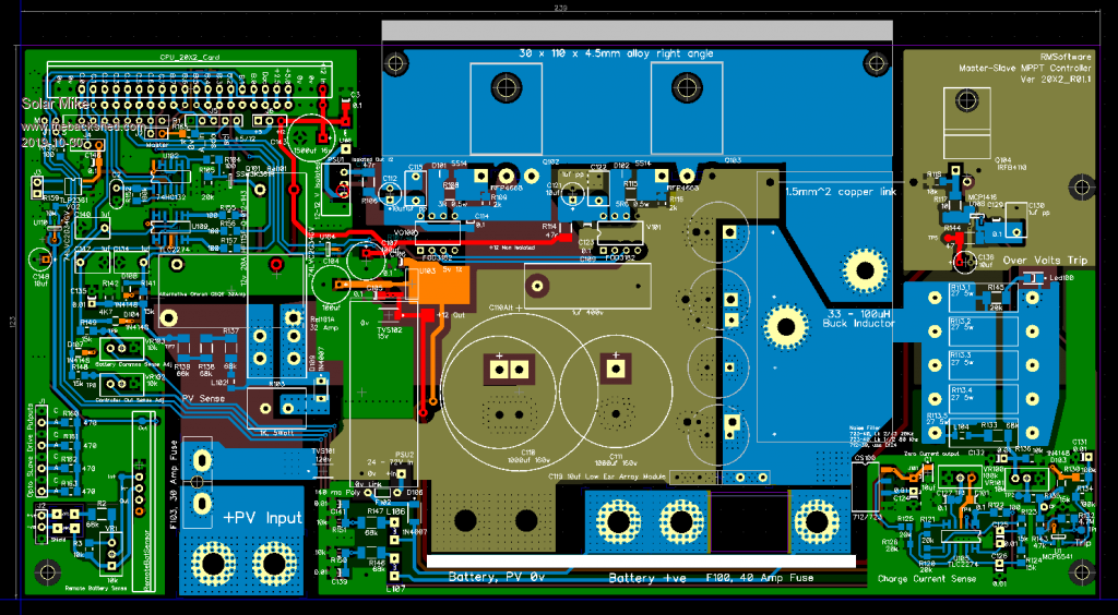 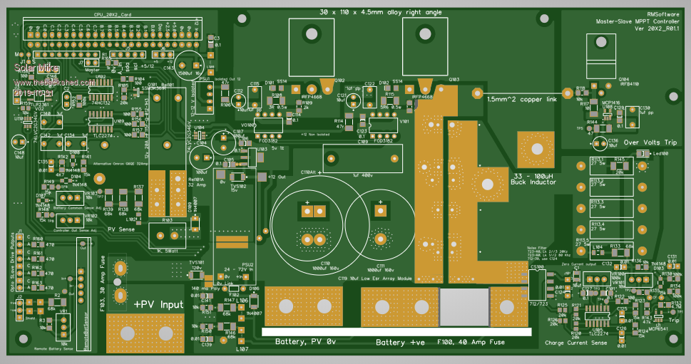 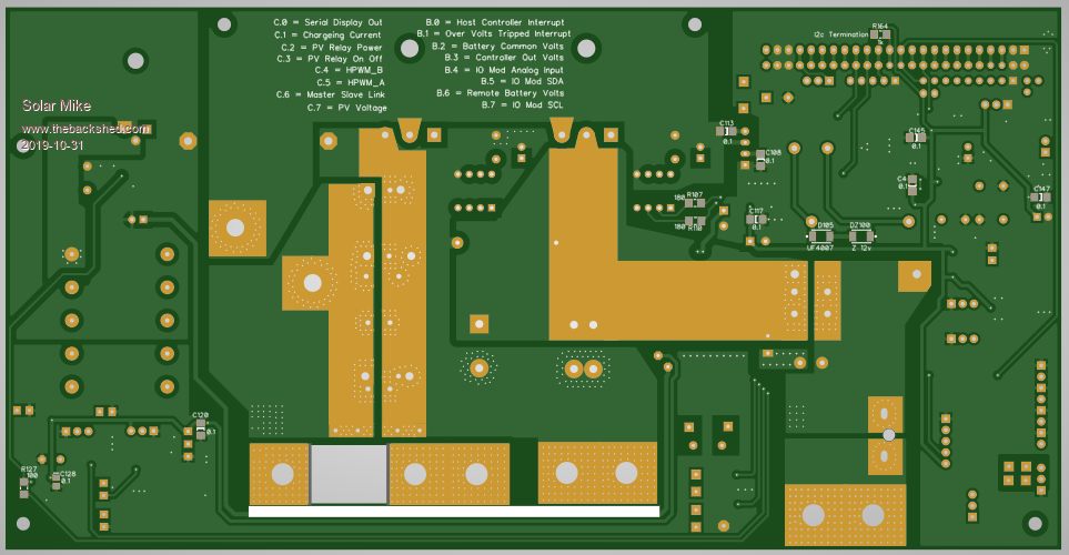 SlaveMppt_20X2R01.1.pdf Cheers Mike Edited 2019-10-31 07:05 by Solar Mike |
||||
| Solar Mike Guru Joined: 08/02/2015 Location: New ZealandPosts: 1204 |
I came across this chip a few days ago UCC21521, it is a 1/2 bridge driver with full control over dead time and is fully isolated, negating the need for additional isolation opto-couplers between the CPU and mosfets. 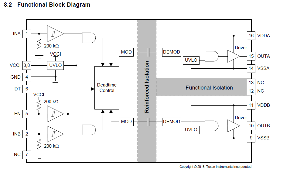 ucc21521.pdf No one sells them here in NZ, so have obtained some samples from Texas Instruments to have a play with; while waiting for the boards to come back for the other slave controller. I have done some testing with the Picaxe 14M2 cpu, three of the PWM outputs can be easily setup for 3-Phase operation at 32Khz @10bit resolution, a fourth phase can be emulated by implementing a delay to move the output in time relative to the others. This means 1 cpu can drive 4 small slave boards (100x100mm) each with a buck and synchronous rectifier driven by the UCC21521. This potentially simplifies the overall design concept a lot, so I will quickly throw a concept PCB layout together, it may make the above 20X2 design redundant. Cheers Mike Edited 2019-11-11 21:19 by Solar Mike |
||||
mackoffgrid Guru Joined: 13/03/2017 Location: AustraliaPosts: 460 |
Mike, I don't know anything about picaxe, but another approach which could yield as many phases as you like is: One central controller which does your ADC work etc, and outputs a 32khz synchronising square wave. Separate controllers, one per converter, would sync on the 32kHz signal. You could use dipswitch (yea, old school) to select phase delay. Having no knowledge of pics or picaxe, I probably would use a STM8 or STM32. Use the 32khz input to sync timer1, which could then trigger (sync) timer2 (PWM) with the phase angle delay. Both these micros are quite cheap. Just a thought. That UCC21521 controller probably has much lower reflected noise - interesting. Cheers Andrew |
||||
| Solar Mike Guru Joined: 08/02/2015 Location: New ZealandPosts: 1204 |
I have thought about something like that, a fast cpu (using C or assembler) could synchronize to and measure an incoming master PWM pulse width, and delaying it by a given phase margin, perhaps even a ATTiny85 running assembler code would work for this, will look into it; Your idea of using dip switch to set the phase is a good one. Ideally the PWM frequency needs to be 100 kHZ or above to keep the inductor size down, with 4 phases the duty cycle of each module will be quite small, so each CPU would have to be quite fast to do that. A pure analog solution perhaps would also work here using a delay line and taps for the phase outputs; would have to be fast enough to pass through the smallest expected pulse width from a PWM input. What I want to achieve is a simple system of modular PCB's each having a buck converter and an accompanying synchronous rectifier, inductor, caps, running on a different phase to each other. These boards would be stack-able to achieve the wanted end charge current output. A master controller would do the actual ADC measurements and output a master or multiple phase PWM output. Cheers Mike |
||||
| Warpspeed Guru Joined: 09/08/2007 Location: AustraliaPosts: 4406 |
That Unitrode UCC21521 is certainly an interesting and very high performance device, but I do have some slight reservations for use in our high powered inverters. It would need to be mounted on the power board up close to the mosfets it is driving, with two isolated gate driver dc power supplies, and with the inherent built in dead time it certainly offers a number of advantages. All of that would be excellent. The non isolated input side of the chip would then require dc power and digital drive signals back to the main control board, presumably through a ribbon cable. And that I think may be a potential weakness. I still personally prefer a pair of inverse connected opto isolated gate drivers driven from a fairly low impedance balanced twisted pair for highest possible noise immunity in a high powered inverter. The UCC21521 would be much more at home where the microcontroller, UCC21521 and mosfets were all mounted on the SAME circuit board, close together, in something like a solar controller. Cheers, ĀTony. |
||||
| mackoffgrid Guru Joined: 13/03/2017 Location: AustraliaPosts: 460 |
Without nutting it out, I dunno about a ATTiny as they're pretty limited. A stm8L050 or stm8L151 are small pin count but but have grown up timers. I think you could set up the timers to do all the work for you, no fast processing required. I think 100kHz would be ok. So with a master clock, wack a little controller on each board to control the buck etc. cheers Andrew |
||||
| Solar Mike Guru Joined: 08/02/2015 Location: New ZealandPosts: 1204 |
Had another think about this, the maximum number of phases I will want is 4 maybe 5, if I go for a 62Khz PWM master clock, the min pwm duty cycle will be > 5us assuming the PV voltage is 2-3x the battery voltage. As I dont have any small fast cpu chips suitable, there is always a simpler way... With a 16us period the easiest way to get multiple phases is to use a simple RC delay line, with say 2us elements. This will pass any pwm duty > 2us with full 1024 bit resolution, I tap off the 0,4,8,12 us delay points and take each one to a buck converter pcb module. Rather than use 74HC14 schmitt inverters as per the generic circuit here, I could use a single 8 input schmitt input buffer 74HC541. 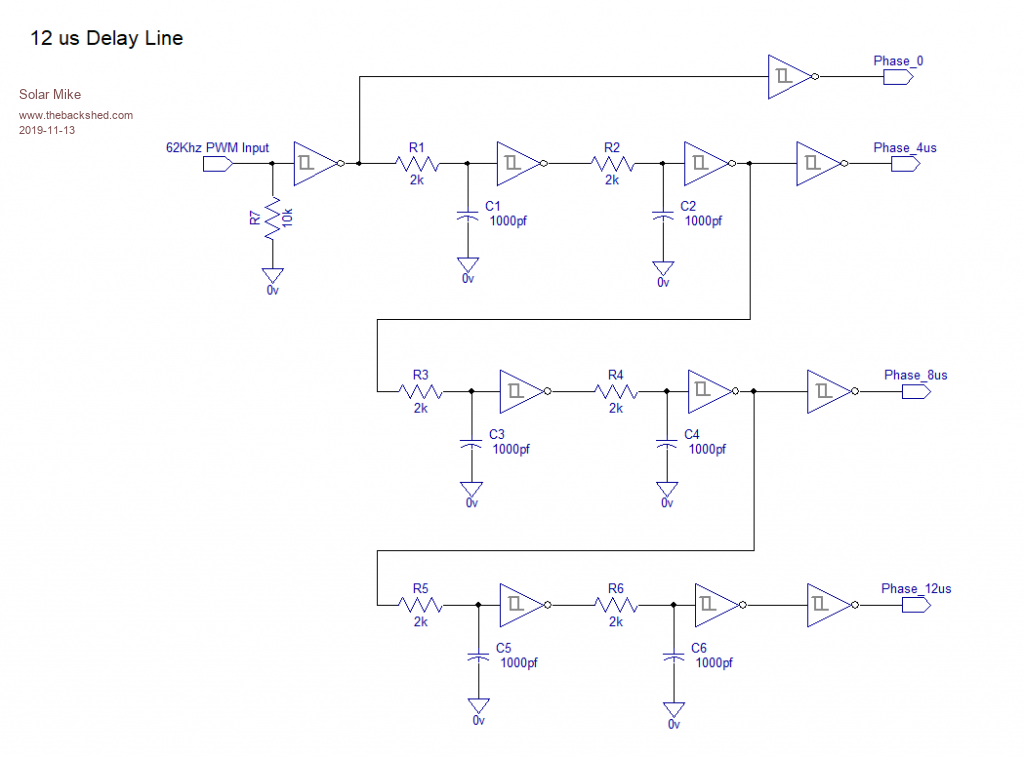 Cheers Mike |
||||
| Solar Mike Guru Joined: 08/02/2015 Location: New ZealandPosts: 1204 |
Whipped up a PCB, its quite small, will plug into the CPU mother board that hosts the Buck Converter modules. Decided 4 phases is all I require; if each one is limited to 30 amps then that gives 120 amp charge @50v battery. 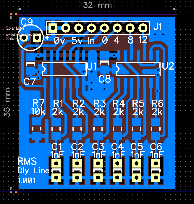 Mike |
||||
| mackoffgrid Guru Joined: 13/03/2017 Location: AustraliaPosts: 460 |
Where there's the will there's a way  Nice and simple (delay line). How big will your 30Amp module be? |
||||
| Solar Mike Guru Joined: 08/02/2015 Location: New ZealandPosts: 1204 |
100 x 100mm PCB, alloy rt angle on one side for 2 mosfets, doing that now. Four modules stack above each other, with Copper Bus-bars connecting the high current points on each module. Mike Edited 2019-11-15 11:42 by Solar Mike |
||||
| Warpspeed Guru Joined: 09/08/2007 Location: AustraliaPosts: 4406 |
Looks very good there Mike. Your Schmidt buffers will need to have symmetrical hysteresis switching points up and down, or the duty cycle will be changed, so the logic family you choose for this is important. Cheers, ĀTony. |
||||
| Solar Mike Guru Joined: 08/02/2015 Location: New ZealandPosts: 1204 |
I have some of these Zetex 74HCS14 that I purchased from RS some time ago, the exact spec cannot be tied down as it varies with temperature and batch variation. I figured the control CPU will take these variations into account in the output voltage\current feed back loop. My intention is the master controller ADC reads voltages and overall output current, setting the PWM accordingly for the slaves that are running with a phase offset. Mike |
||||
| Warpspeed Guru Joined: 09/08/2007 Location: AustraliaPosts: 4406 |
74HCS14 should work pretty well, because they are designed for 5v rail to rail swing with the logic threshold theoretically set in the middle. 74C14 chips should work too, but are slower. But delay is what we are trying to achieve. I once used a long string of cmos CD4050 buffers as a delay line for a 1Mhz clock signal. The six stages in each package produced a total of about 200nS delay and it worked very well. Its the TTL compatible cmos chips you need to be a bit careful of, because they have the logic switching threshold set to be around 1.5v not 2.5v. So its the 74HCT14 and 74ACT14 chips that might give you some grief by producing different delay times when switching in either direction. It might still work though, because all the stages are cascaded and each stage inverts the signal. But it might go a bit "funny" at either very high or very low duty cycles and stop working, so you will not be able to reach the extremes of duty cycle. Anyhow, definitely well worth a try ! Cheers, ĀTony. |
||||
| Solar Mike Guru Joined: 08/02/2015 Location: New ZealandPosts: 1204 |
The last time I built a delay line was over 30 years ago, used to use them to get correct timing signals for driving dynamic ram chips driven by Z80 cpu. Guess there is no call for them now except for Audio reverb and sound effects. I haven't tested this one, all theoretical design, as per the rest of this project. PCB almost done, difficult to squeeze these power components into a 100mm pcb. Cheers Mike |
||||
| Page 1 of 3 |
|||||
| The Back Shed's forum code is written, and hosted, in Australia. | © JAQ Software 2026 |
