
|
|
Forum Index : Solar : Solar Hot water system (thanks to forum, Warpspeed and others)
| Page 1 of 3 |
|||||
| Author | Message | ||||
| KeepIS Guru Joined: 13/10/2014 Location: AustraliaPosts: 2184 |
A bit of background: I have been building an emergency solar backup system after someone gifted me two old Solar systems. Both about 1.5kw each and around 10 years old. That led me down another rabbit hole and finally I have a system running better than I had initially thought possible, especially for the price. Mostly I used the lowest cost Solar regulators (3 X 60A) and 5kw 10kw peak inverter (which really does 10kw) in a 24v system. However I didn�t make the mistake of skimping on the Battery quality and I added another 3kw of quality new 400w panels along the way, prices were really low when I got those. The 12 year 2.8kw old grid feed system is left as is as the feed in tariff is still high, when they pull that, I have a new combined inverter / battery charger and battery to run that separately plus a few panels to add to it. FYI I can instantly start a huge very old 2.5 HP compressor that draws 455 Amperes on initial start up, a heavy duty Bandsaw @ 374A surge and that�s with everything else running, big fridge freezer, Aircon, lights, washing machine, computers, big ventilation fans etc, like I said, exceeded my expectations. I coded and built a solar data unit giving full real time graphing with history, it has a 9� touch screen so easy to read, running an ARM H7 Micro, complete system has not skipped a beat while running for the past 10 months. Now onto the Hotwater system. 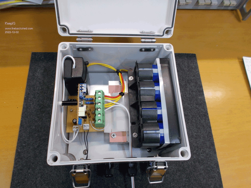 This was built into a nice Weather proof housing,and designed to be easy to service and experiment/modify, to this end I made a base board (mother board) that holds the SSR IGBT's and the high voltage parts and connections, a daughter board simply plugs in and can be removed with just one screw. The neat thing about this is that it can be run on the test bench and adjusted without disturbing the controller installation. NANO:Inverter V 8.2ks - Linux AvrDude GUI script V4.1 |
||||
| KeepIS Guru Joined: 13/10/2014 Location: AustraliaPosts: 2184 |
Some info on the solar and HWS. I have a small 50Ltr 2.4kw HWS as an emergency backup. Now I know that�s a small unit, but I hooked it up direct to solar 4 days ago and it ran for almost those 4 days as the only source of hot water until the 24 hours of drizzle and total cloud cover hit. Only two of us, hot showers and dish washing no problem and then ready for the next night. Just the thing I need to do real world tests. I can easily heat that from cold to thermostat switch off on my (240vac) Solar backup system in a around 2 hour or less, same as if it was on mains. However I have 6 old panels left and decided to see what it would take to heat that small HWS up to full temperature. The 6 panels should have a VOC of 267v but I can only get to around 235 (they are yellowing). The power rating new was 185w x 6, or around 1kw, Vload new was 37.0v @ 5.1A. So I direct fed the HWS with the panels, on a good day I could heat the system to thermostat off in around 4 hours from cold, I really did not think that would be possible. On a bad day � gets hot, but not quite thermostat switch off, on a bad day not good obviously. �Over the past week, the most I�ve seen was 125v @ 5.4A = 675 Watts (fleetingly) into (27 ohm DC resistance) 2400 watt Heater element, most of the time in good sun it sits around 100v to 120v @ 3.5A to 5A. I found the great work by Warpspeed when I remembered the Solar forum here. I just finished building a HWS controller based on his design. 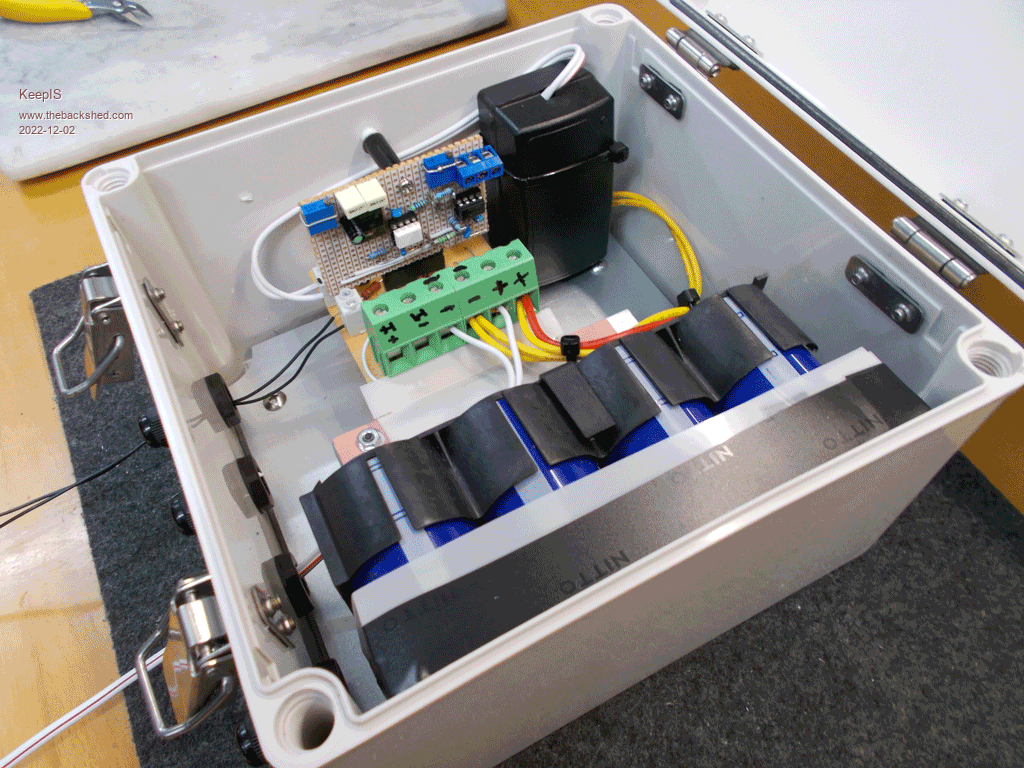 The Capacitors run slightly warm, so they are working, the SSR I made with 3 x IGBTs salvaged, like almost everything else, from a few 10 year old inverters, the IGBTs are rated at 600v @ 30A at 150 deg, and very low On resistance with 3 in parallel of 0.002 ohms, so 600v @ 90A for 3, needless to say it runs almost cold, no fan, and it�s inside a sealed box, it�s just a solid lump of square aluminum heat sink about 50 x 50 x 150mm long. Edited 2022-12-02 19:23 by KeepIS NANO:Inverter V 8.2ks - Linux AvrDude GUI script V4.1 |
||||
| KeepIS Guru Joined: 13/10/2014 Location: AustraliaPosts: 2184 |
I came up with a simple low cost way to get voltages from 60 to 300 volts DC on the work bench in a relatively safe isolated mode for initially setting up the switch points and fault finding. So having just finished getting this going and installed, I thought I would share my results and a few things to watch out for with setting up and building this type of HWS controller. � I added a Thermostat connection and have used the existing thermostat successfully, well, once I solved a strange issue that could have overheated the IGBT or MOSFET solid state relay (SSR) Today has been overcast with a few brief patches of sun, the NEON was pulsing at around once a second for most of the day, with the glimpse of sun it flashed at around 4 times a second. I had it installed and switched it on at around 9.30, by 4pm it was too hot to hold onto the water outlet or pressure release. No the thermostat did not reach turn off temp but you could not stand under the shower without cold water mixing, and I also have a mixing valve installed on the HWS. So not bad for such a lousy day and a small old solar panel setup. The Neon never stayed on � nor could it � I have the low cut-off set at 130v �and the High cut-off at 210V, this small solar feed can NOT supply 210v with the HWS load. The point is, �the DC current clamp meter was showing almost 7A at times, but of course at a low duty cycle (switching time) Tomorrow I will put the Digital scope on it and see what the real power is compared to direct feed, should be interesting. 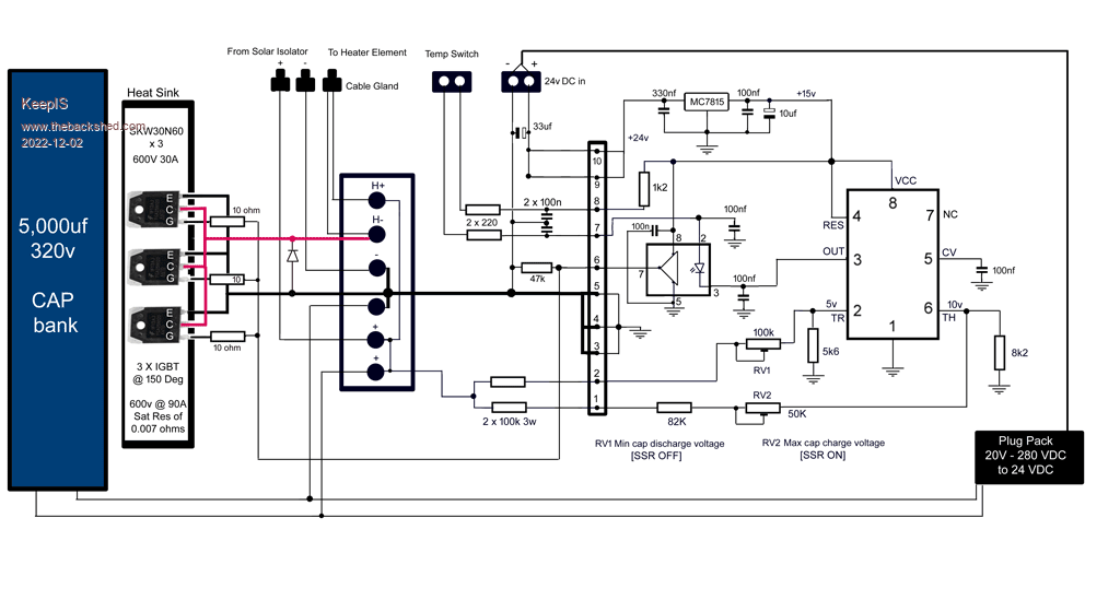 This is the circuit, the left side of the 10 pin connector is the base board, the right side is the daughter board. Note that I used a standard 240vac plug pack as I wanted 15v for the control voltage. Most device are rated at 15v gate voltage when the quoted on resistance and current limits are specified, I wanted to eliminate anything that could cause the SSR to run hot like, slow switching transition, noise or slightly low saturation voltage could cause some of these problems. I found a condition where the 555 would oscillate and could possibly cause an overheat condition for the SSR. More on this later and a noise problem when using the HWS Thermostat, both simple fixes with a few bypass caps / filtering. Mike. Edited 2022-12-02 19:39 by KeepIS NANO:Inverter V 8.2ks - Linux AvrDude GUI script V4.1 |
||||
Revlac Guru Joined: 31/12/2016 Location: AustraliaPosts: 1281 |
Nicely done.  I have built one of Tony's Solar Hot Water pcb's, but only up to testing stage, the HI/LO switching (using trim pots) on the 555, is working with some playing around, but found the Gate driver IC is not switching, I was planing to change its power supply from the 11.9v to around 15v and try again. Thanks for posting and explaining your setup.  Cheers Aaron Off The Grid |
||||
| KeepIS Guru Joined: 13/10/2014 Location: AustraliaPosts: 2184 |
Thanks Aaron. Likely you noticed the 10 turn Trim pots in mine. Makes life easier when experimenting. One thing I noticed was when the On/Off voltages are close together it goes crazy (need a CRO to see that) but could cause heating problems if left unchecked while testing, I found a 0.1uf on the 555 pin 3 almost stopped it completely and did not cause any switching response changes through the Optocoupler driver. BTW I have 3 test points bought out on a 3 pin connector on the top edge of the board near one of the trim pots (small blue connector in the pix), the meter probes fit in this nicely, I have Pin 2, 6 and 3 of the 555 on these. Now I can check exactly what voltages the HI/LO pins are reaching and also watch the 555 output pin for HI/LO transitions. Just came out this morning and the Unit is flashing away nicely, that neon was a great idea, so simple but mostly overlooked these days. Cheers Mike. NANO:Inverter V 8.2ks - Linux AvrDude GUI script V4.1 |
||||
| KeepIS Guru Joined: 13/10/2014 Location: AustraliaPosts: 2184 |
The Thermostat connection. I made sure that the thermostat switch could be, and was, completely isolated from Hot water system earth Heating element and supply. The controller was built before any decision had been made for the Thermostat connection into the circuit, I did however include a connector for the thermostat and two 220 ohm resistors in series with each lead from the thermostat connector and 2 allocated pins on the base board 10 pin socket. Once I confirmed that my controller actually worked, I decided to try a quick mod to make the thermostat switch simply interrupt the 15v DC connection via the 1.2k resistor feeding the Optocoupler Diode. When I tested it, the SSR Heatsink now started to get quite warm and the 15v regulator was getting hot, I also noticed the NEON was dimly glowing instead of turning completely off, this could only happen if the 3 IGBT devices that make up the SSR were in partial conduction. I guessed that the on/off pulses from the heater element were inducing noise spikes into the Thermostat wiring. I added a 100nf cap to each 220 ohm resistors to ground to act as a simple RC filter and placed a 100nf from pin 2 of the Optocoupler to ground. Problem solved and it now works perfectly. BTW. The Application data for the Optocoupler FOD3182 states that a 100nf capacitor MUST be connected between pins 5 and 8, these are the DC supply pins and normally the cap should be as close to the pins as you can get. Note: I had already included this for pins 1 and 8 of the 555, although not shown in my circuit, I solder these tiny bypass caps directly across the pins of the IC on the bottom of the board, it's just a habit I have from chasing so many instability issues in integrated circuits over the years. Kind of like giving the finger to Murphy�  The test setup before making a permanent connection to the HWS, the thermostat wiring is the White/Red cable with a knot in it, there was a nice small hole in the HWS case just below the Power inlet, so no modification to the HWS at all. 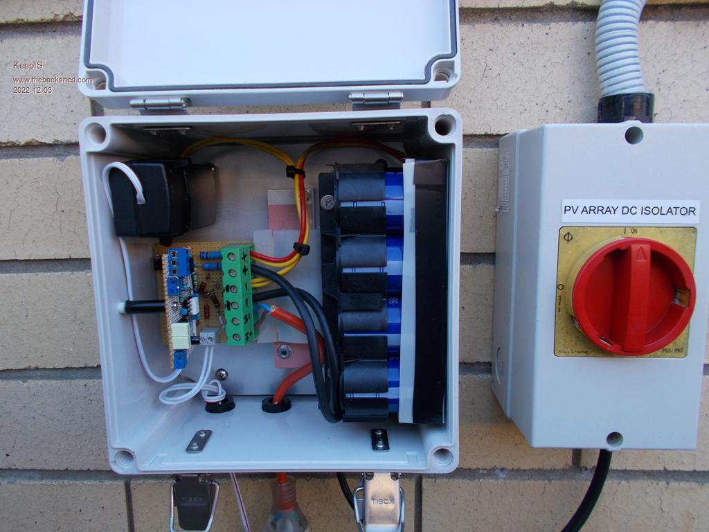 Edited 2022-12-03 08:26 by KeepIS NANO:Inverter V 8.2ks - Linux AvrDude GUI script V4.1 |
||||
| KeepIS Guru Joined: 13/10/2014 Location: AustraliaPosts: 2184 |
Today is a good day to do some testing, cloudy to dark with short periods of clear bright sun. The water in the HWS was slightly warm after overnight use when I checked the outlet and release valve water at 6am as when I switched over to the big HWS. I started my test at 9.00am and on this cloudy overcast morning which at first looked like no sun was going to show, the controller still got the outlet of the small HWS hot. Now obviously starting off warm helps, but it shows that this controller, even pulsing at around once or twice a second is working really well. I had a Digital CRO looking at the Gate Drive waveform for any sign of noise and there is nothing but a perfect Square wave drive swinging from zero to 15v at the IGBT gates, in all conditions from off no pulse to full on. I had a DC clamp on the Solar input and at 125v I was getting 5A (625w) direct connected to the Heater element, from there the current dropped off very quickly. Having the trim pots is great, I reconnected the Controller and simply adjusted the SSR (IGBT) low cutoff to trim pot until the NEON stayed ON while monitoring voltage on the CRO. The input from the solar panels is now swinging from 125v to 220v, and for quite a bit of time I have the NEON hard ON (no pulse). I may have been a bit harsh about those old solar panels, today I'm seeing voltages around 161v @ 6.7A. I remeasured the heater element with a known calibrated DVM and it's 23.9 ohms (24 ohms), I confirmed the current reported by the clamp meter was correct, the power is 1.07kw. When new, these 6 panels in series were rated at a V-load of 229v @ 5.1A, so theoretically in ideal conditions they might have made 1.4kw? so 1.07kw 10 years later is not bad??. The discharge time is, as expected, very fast, so when you look at the NEON, it is displaying the charge time, the NEON off time is the actual power delivery time. However that short pulse is around 2kw in this small system. To recap: Old Solar panels mounted FLAT on the west side pergola, shaded in early morning, still raised the temperature from luke warm to hot in 3 hours (pressure release valve dripping, HWS is only 6 month old) between 6am to 9am on an overcast morning. No it's not scientific, just an observation, and all on Low duty cycle slow pulsing. This tells me there is real potential for this controller. The only real way to see a difference between direct and the controller is to fit a 2.4kw jug (I have one) with a minimum volume of water and measure the temperature change over a short period of time, around 20 seconds or less if possible. Going to try that after lunch. Very interested to see what it does in both low solar and pulsed verses direct at higher power. Mike. NANO:Inverter V 8.2ks - Linux AvrDude GUI script V4.1 |
||||
| KeepIS Guru Joined: 13/10/2014 Location: AustraliaPosts: 2184 |
I checked the controller as I went in for lunch, just a few seconds after I added the last post. The NEON was not flashing, my first thought, I might have done something wrong during the tests. Then a far out second thought, I had a small jumper wire from testing and placed it across the thermostat terminals, and low and behold, all working. The HWS had reached its design temperature and tripped the thermostat, it was totally overcast and now as I write this it's raining. Test will have to wait. So, short high power pulse controller works. Basically I found the point where I'm still making a bit less than half power from the panels and set that as the low cutoff, obviously set the high cutoff near the Maximum power point voltage, measure if possible when using very old panels or go slightly less, just MHO. OK, it's a small tank, but when the big green fuse blows, for weeks at a time, or longer, I will still have hot showers (I'm over 70, I need my warm shower), maybe not every day, but if it rains that much then we'll all need an ARK and paddles instead. I'm so impressed with this now that I might just grab five 400w panels to power it. Such a simple robust system if you get the SSR made correctly, that means high voltage head-room (around 400V to 600V) and SSR running only slightly warm, without a fan or massive heatsink. Just get some good Mosfets or IGBTs, BTW there is NOTHING wrong with a good IGBT, no changes to the circuit to use these as I have. To run cool you need very low on resistance, (RDS(ON) or Vce(sat) for IGBT. The on resistance along with current capacity is made lower by paralleling, get down to 0.01 ohms or less if possible and check the device spec is measured at 150 deg for both current and resistance, not room temperature as is often quoted. Mike. NANO:Inverter V 8.2ks - Linux AvrDude GUI script V4.1 |
||||
| KeepIS Guru Joined: 13/10/2014 Location: AustraliaPosts: 2184 |
Off topic but here is a picture of the one of the many screens on my solar information display. This is showing a history graph from mid morning, I was making a coffee on the Espresso machine and using a small milk heater/frothier. The unit has around 10 different screens including accumulated data KWh & running hours. Battery sets and each Solar array voltage, current & power. Load voltage, current & power, battery bank charge AND discharge, current, voltage & power and of course everything is graphed, including instantaneous peak values for all of the above. 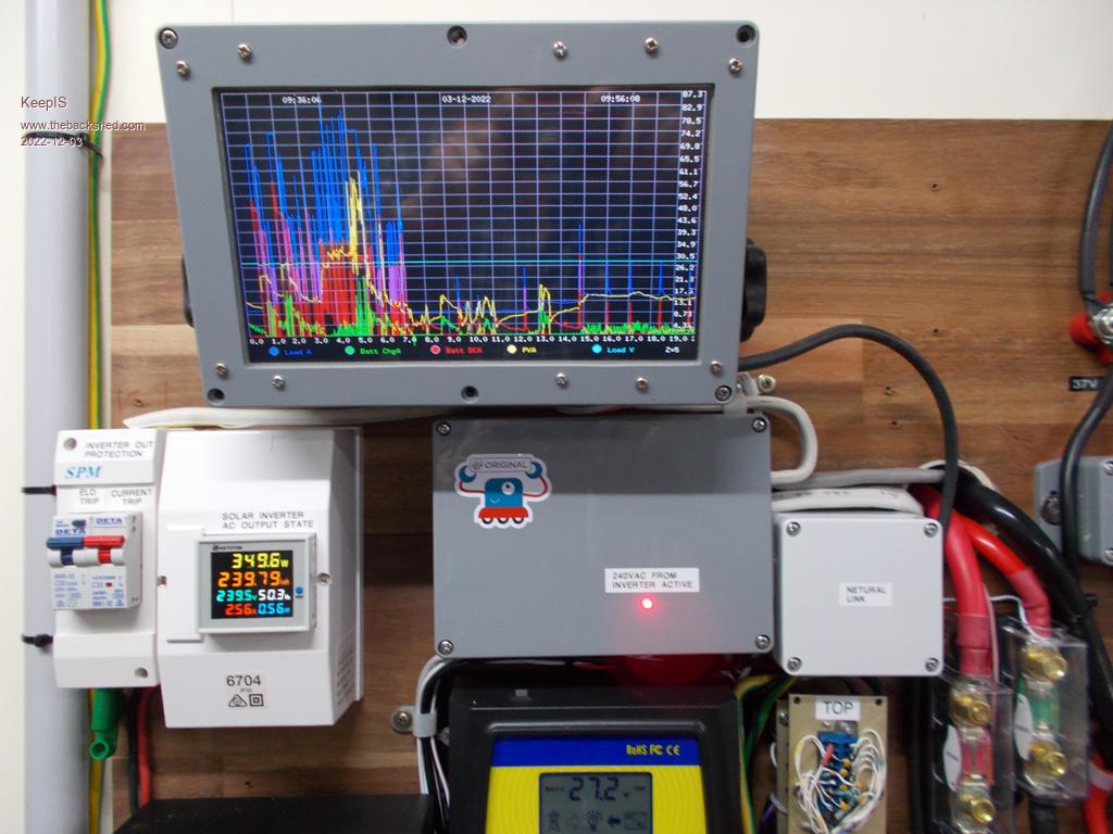 NANO:Inverter V 8.2ks - Linux AvrDude GUI script V4.1 |
||||
| KeepIS Guru Joined: 13/10/2014 Location: AustraliaPosts: 2184 |
A few notes on getting the controller to run on the bench or the solar panels. I was powering the controller from a simple low cost and easy to make low current fully ground isolated adjustable 250v DC supply on the test bench, instead of the solar panels. NOTE although a DC input may have very low current capability, once it charges the BIG Caps in the controller it becomes extremely dangerous and extreme caution must be observed. � � � When the device was connected to the bench DC, the 555 output transitioned from LO to HI and the SSR was switched OFF. I observed that the 555 output would not change state until the input voltage cycled, IE: went back down below the LO cutoff point and then up to the trip point. This may have been be due to the test setup, but something to check if it appears to be not pulsing. (I might revisit that when I get time) If you have the low cutoff voltage set to LOW, or it's not tripping off for any reason, and the device appears to be partly working but at a very slow pulse rate, then the following may be happening: If solar output availability is low and the solar input voltage drops under the load of the heater element to less that 30v to 50v volts, the small DC to DC converter supplying 12v (15v in my case) will start to drop, the SSR will (should) switch off before the voltage gets to zero (the 555 may still be running) and in doing so, allow the solar voltage to rise again to the HI voltage trip point, the SSR will turn on, and the same loop will repeat with the NEON flashing at a very slow pulse rate. Mike. Edited 2022-12-03 16:28 by KeepIS NANO:Inverter V 8.2ks - Linux AvrDude GUI script V4.1 |
||||
| Davo99 Guru Joined: 03/06/2019 Location: AustraliaPosts: 1585 |
I could not get the one Tony built me to work either and couldn't figure it out. Let me know how you go with yours as I really would like to be able to use this but I am sadly lacking in knowledge to know how. |
||||
| Davo99 Guru Joined: 03/06/2019 Location: AustraliaPosts: 1585 |
Using a Neon could be very helpful to me. I'm no where near smart enough with this to do what you have so I took a much simpler approach. I figured the object of the game is to keep the panels in their happy place by not boggoing them down. Instead if using the voltage monitoring to switch the caps to the load, I just used a fixed Cycle timer. I have tested it and it seems to work Pretty well. The caps seem to present little load to the panels and switching them at 10 Hz seems to be too quick to drag the panels down too much ( they are permanently connected to the caps) But I was wondering if that's sufficent time for the caps to dump their power? I don't have the gear to be able to see this but the neon may be helpful in seeing this. If I lenthen the on time I could then put one on the input and one on the output and get an idea by the time they stay lit. the way I tested so far was to get a 500W halogen globe and connect it to the output and change the timing till I got the brightest output from it. I figure as long as I don't fully/ over charge the caps, then all the power from the panels will be going to the load so that should be mission accomplished. To that end I made up some pretty decent cap banks As I like to run some decent power through the setup ideally. I'll get some neons and see if they give me a better idea for Tuning the system. IF the thing is switching when the caps are only partialy charged, don't see that as a problem as long as the switching is fast enough not to let they fully/ overcharge at peak times which would waste power. |
||||
| KeepIS Guru Joined: 13/10/2014 Location: AustraliaPosts: 2184 |
Most NEON globes strike at 90v (glow) they draw a few ma and an appropriate resistor is required in series, you can get then rated @ 240ac with the resistor installed in a small housing (around 240k resistor from memory) but the neon itself is about $1.25 or less, I think I used a 100k for this purpose. I have not shown the neon in my circuit and I will update that. My version is almost exactly the same as the one you have, just modified to work as a base board, and plug in daughter board. It takes all of 4 seconds to remove the daughter board to modify and experiment with. I did this to virtually isolate the high voltage DC from the daughter board, I'm extra careful around these voltages due to my age and two recent heart attacks. That's why my cap bank is completely enclosed �  . � . �You don't have to worry about the cap discharge time, it is almost instantaneous when switching them across a low impedance load like a 12 to 24 ohm restive heater element. There is a more complex arrangement happening here that is a mix of the thermal sink that the load is exposed to, like the heater element in water, and that changes with the temperature delta between the water in the tank and the element temperature, so the efficiency of that short pulse from the CAP bank is not static. Then you throw the Solar panel size and power curve into the mix and it's not just a simple switching time algorithm. The Cap bank is not completely discharged in each cycle, the waveform across the caps swings between the upper voltage discharge point and the low voltage trip. In may case from 120v to 210v, so a 90 volts charge discharge cycle. It's a simple matter of directly connecting the load and checking the current into the load verses the voltage under low solar conditions, in my case I found the low point of 125v @ 5.1 gave me 600 watts, below that the power dropped of rapidly. So having got my low switch point, the high discharge point is the max power point voltage, or a bit lower if it appears stop charging in half decent solar conditions. So Charging time for the most part is pretty fast, but then you have the conundrum of how much cap is the sweet spot for the chosen load  I know various ideas have been talked about for measuring the real power delivered �to the load with this type of controller. My plan now is to quickly code a small fast micro to simply measure the power flowing to the load with a power measurement taken ever few microseconds (or as fast as the code will run), this should show accumulated / averaged power per second, the idea is to get a fast running total displayed and hopefully get a pretty good idea of the real power to the load. � Apology for long post. EDIT: I forgot to add: The idea of the micro measuring power is that it's very simple to then have the micro control/vary the switching to achieve the max power into the load under all conditions. Mike. Edited 2022-12-04 08:56 by KeepIS NANO:Inverter V 8.2ks - Linux AvrDude GUI script V4.1 |
||||
| KeepIS Guru Joined: 13/10/2014 Location: AustraliaPosts: 2184 |
I posted at 2:08pm yesterday the HWS thermostat had turned off around 11.50am on a pretty overcast morning. At about 4.00pm it turned back on. Overnight we used hot water as normal, Both of us having nice long hot showers, hot water for dishes etc, and still nice and warm for washing and dishes this morning. Today was completely overcast until around 7.30am with glimpses of sun from then on and a little brighter despite still being overcast. At 5.30am I checked the neon and it was actually flashing about once a second, if there had been any sun at all, these panels would be shaded at that time, but it was heavy overcast and looked like rain. I checked the HWS again at 8.45am, which we have been using as normal this morning and the Thermostat is now off, I can't even touch outlet for more then a few second. Seriously this is just crazy good. I'm now wondering why I should even bother measuring anything. I will thought, purely because I am intrigued to see if it's possible to improve on this. There is something to be said for a small system for emergency use in extended blackouts and poor solar/weather conditions. I think this system with around 2.5kw of panels instead of the 1kw and a bit I currently have would be a really great system. My thermostat control circuit modification is working perfectly. BTW: The Heatsink is running almost cold inside the small sealed box. I measured my Heatsink size again, and it's smaller then I thought @ 20mm x 30mm x 110mm of aluminum rail, this rail holds the FETS or IGBTs, and would normally be bolted to a very large finned heatsink for heat transfer. Get the Vsat (on) resistance down and you solve your heat problems, it's simple ohms law. Mike. NANO:Inverter V 8.2ks - Linux AvrDude GUI script V4.1 |
||||
| KeepIS Guru Joined: 13/10/2014 Location: AustraliaPosts: 2184 |
This is wrong! When I wrote that I still had the images of the Digital Storage Oscilloscope (DSO) connected across the Heating element, this is also where the NEON is connected. The discharge transient is very fast, and the NEON pulse appeared to be out of sync, so I wrote what I thought I was seeing. Memo to self, look at the circuit before posting �  � �Of course the NEON flashes for "SOME" of the cap discharge time, which is very fast in itself. However revisiting this has also highlighted a few things that I had not noticed in all the fun of getting this working, and having hot water from the sun. The first thing is this: The voltage across the CAP bank does indeed swing between the HI discharge trip point and the LOW voltage discharge cutoff point, it does NOT discharge to Zero. The waveform looks rather like the teeth on a saw blade, there is a rounded arc as the CAP bank charges followed by a sharp concave section down to the LOW voltage cutoff point. Using my 2.4 KW Hot water system as an example: The Low voltage discharge point is currently set to 125 volts @ 5.1A or 600 watts. The Hi voltage trip point is set to 215 volts (allowing for old solar panels). So the CAP discharge voltage is 90V into my 24 ohm resistive heating element giving me 337 watts each pulse, does not sound like much but it works. � MAX CAP charge � � : 215v MIN CAP Discharge �: 125V � � Pulse Load voltage : 90v Power into load � �: 337 watts You can't really maintain an MPPT state with this controller, and really there is no need to in this situation. To clarify, if you dedicated a very large solar array with a lot of current and voltage capability to the constant KW load of a heater element then you might get close to MPP sometimes. So we find that the voltage differential for the Pulse needs to be as high as possible to maximize the pulsed power into the Load. The Pulse repetition rate needs to as fast as possible, so charge time has to be considered- it's a balancing act. Using the figures above: I need to lower the LO cutoff down to around 300 watts. I need to raise the HI cutoff right up to the MPP voltage, or higher if that is attainable in the chosen low Solar operating condition. The cap is almost fully charged at MPP and the charge current should be low so a few extra volts could be added quickly. � � � Then we have: MAX CAP charge V � �: 225v (still the MPP for this panel setup) MIN CAP Discharge V : 115V � � Voltage in Load � � : 110v Power in load � � � : 504 watts per pulse. Back to the NEON, as the voltage pulse is only between 90 to 110 volts in this system, the series resistor in the NEON can be reduced to around 10K, this will make the NEON much brighter and increase the conduction time giving a more accurate visual of the discharge pulse, if you really want to get the fastest indication, use a LED. Thoughts, errors ? BTW: This controller is designed to extract some decent power for heating the element in poor solar conditions where the available power from a direct connection would be very small, say from 10 to 120 watts, this controller shines in these conditions and can extend the useful heating time by hours. � Mike. Edited 2022-12-04 19:42 by KeepIS NANO:Inverter V 8.2ks - Linux AvrDude GUI script V4.1 |
||||
| KeepIS Guru Joined: 13/10/2014 Location: AustraliaPosts: 2184 |
Since I started this post, I may as well add a �bit more test info just in case anyone is interested. We have not used the Main Hot water system for past couple of days, just using this little HWS now the same as we would use the Big unit. I turned the thermostat up to full yesterday and after overnight use, the water was still warm enough for house hold use this morning. I dragged my Analogue / Digital storage scope out (A very different beast compared to the newer true Digital Scopes) �I have both, and started to get some data. A nicer day today, some clouds and sunny: At 5.30 am: Direct feed power, nothing ! Panel output pulled down to 20v. Controller enabled: �Pulsing the element with around 350 watts every second. 7.30 am: Direct feed: �60v @ 2.5A �- 150 watts Controller : �pulse every 150ms. 338 watts, PWM, so one would assume less averaged. Then a few more readings as more light and a bit of sun gets to the flat mounted panels. Controller Pulse rate now every 100ms: � Direct 63V � 165w �- � Pulse 338w � � Direct 74V �228w � - � � � � � �� 8.30 am: 114V - Pulse stops and now controller goes direct. 114V �550watts - direct By 8.30am 130v - 760watts 9:30 am: I�m still doing my testing, then everything appears dead. No, not dead, the HWS is at full temperature, thermostat on highest reading turned off � feels like I would burn my hand if I tried to hold the Hot outlet or Pressure / Release valve. The advantage of starting out with some warm water left. If I double the panels (parallel) it just might be good enough even in winter when the Public power goes south the way a lot of us expect. Got a lot of Stored Waveform to go over but everything looks good except for some instability issues with the 555 that I managed to catch on the Dig-Scope. � � A few problems with the 555 in a box in direct sun, it�s low trip point appears to shift up a bit. Starts pulsing when it should just be on. �The 555 is also is very sensitive to any noise or coupling on Pin 2, even on the test bench, just putting a very HI-impedance DVM on pin 2 can cause it to switch off if it�s close to the trigger voltage, maybe the 280 to 24v SMPS I used is dirty, (RF noise on the input/output) Pin 2 is also where I was seeing massive instability and RF like waveform, it causes the 555 to suddenly draw more current and run hot, also causes the Opto Driver IC to get hot, luckily I saw it on the scope during testing. I fitted a 0.1uf to ground from pin 2, it does not affect the trip point or transition in any way, and it absolutely stopped the instability. I�m going to wire up a new daughter board with the new mods and revised layout to see if that helps, and put up a small sun awning for the outdoor box. Simple job. At the moment almost completely running off grid (except for the Big oven) but have a smaller 2kw oven that runs easily on the 5kw inverter. Plugged an old 1 liter electric Jug into the HWS socket and these 6 old panels managed to boil 1 liter of cold water in around 4 minutes. I'm not in a hurry. BTW The waveform across the heater element is very interesting and it's voltage swing is a lot more that I anticipated. Mike. Edited 2022-12-05 19:23 by KeepIS NANO:Inverter V 8.2ks - Linux AvrDude GUI script V4.1 |
||||
| Revlac Guru Joined: 31/12/2016 Location: AustraliaPosts: 1281 |
Yes Still interested, was going to comment last night but run out of time, trying to keep up. I imagined the it would look like a sawtooth on the scope, the gap between would get shorter as the power input increases, and power measured on the input from solar, I think that is better than measuring the HW side. If the heatsink is cold thats great, the one I have used is small, out of a radio Amp, so should be ok. I did do a test run with panels direct to the HW system, (I had notes somewhere) and it was plenty hot enough by the afternoon, provided it was a full sunny day. I haven't tried boiling a kettle but I did had an old hotplate, 900w I think it was tried that direct from the panels and eventually it would boil a kettle that was normally use on a gas stove, mostly to see what the loaded voltage was coming from the panels, think it was 120vdc. Interesting, I think someone else may have had this instability as well but never got to the bottom of it yet. Before I make any more assumptions I will have to get back to this and have another go. Thought I had ordered some FOD3182 back then but all I have is TLP250 on hand, will make do with them. Very good, the small ovens can do most of the work, this one also has a stove on top and some confusing dial switches on the front, we found that the two can be running at the same time by mistake, that used a lot of power from the 5Kw HF 48v inverter. Also I notice that the toaster and kettle take more time to complete there task when using 230VAC compared to the 240VAC (or a lot more) that we used to have from grid, so I expect the HW will take much longer than usual, but that will not matter.  Cheers Aaron Off The Grid |
||||
| KeepIS Guru Joined: 13/10/2014 Location: AustraliaPosts: 2184 |
Funnily enough it does not change that much, however the Gate Drive is a constantly changing PWM. One thing though, when trying to measure pulse mode, the power from the Panels is not the same as the discharge power from the caps. So have to measure across the Element. Panels were delivering 900w, the 1L jug boiled in just over 4 minutes. Timed on the mains (239vac) 3.5 minutes. It's 1.8kw element and I thought there would be more time difference, however conditions were good yesterday, the heat today will drop everything back. I didn't realize that the 555 can get quite warm? If it becomes unstable it runs hot. It also Makes the FOD3182 run hot. Interestingly the FOD3182 does not drive the IGBT SSR gates with that garbage waveform - Output just sits low (which is nice). Out small stove is actually a large Air Fryer/Oven, around 2kw, Inverter loves it as it heats up quickly then does its on/off cycle with "lots" of off time. The mains here is usually around 239 to 245, I reverse engineered a circuit for my $650.00 5KW/10KW Inverter, along the way I adjusted it to 240vac. Ordered a bag of spare FETS and IGBT. I could also use most of them if I decide to make one using a toroidal transformer. Just not sure what to get for the driver board. Something for down the track, I have scavenged 1 big transformer, just need to find another old grid inverter with one. Mike. NANO:Inverter V 8.2ks - Linux AvrDude GUI script V4.1 |
||||
| KeepIS Guru Joined: 13/10/2014 Location: AustraliaPosts: 2184 |
I've been looking over the Pulse Discharge waveforms that I captured on the scope connected across the heater element, and I noticed something interesting. The Discharge cycle at that time (early morning) was 130ms. Cap Charge point before firing the SSR is set at 210V. (Panels only get to 237v OC) SSR turn off (start recharge cycle) is set at 100V. The thing is, it's classic RC discharge with what appears to be around 70% of the discharge (the bulk of usable power) completed in 70ms, the remaining 30% takes another 60ms. It may be way more efficient to raise the low cutoff point to around 120v or 130v in this test system. Higher voltage discharges faster into the fixed 24 ohm element resistance. By shortening the discharge time to the higher part of the �voltage curve, the repetition rate does increases rapidly and easily seen on the flashing NEON, the result should be fast higher power pulses. The Heat today made me realize that I need to move the Controller and Solar Disconnect switch out of the sun and under the pergola, doing that first thing in the morning. FYI: I rebuilt the daughter board today (basically the 555 timer, Opto driver chip, trim pots and regulator. The new layout with various mods from testing has solved all the issues I was having. Just need some freezing rainy weather to test properly. Our 250L 3.4Kw off peak HWS is still bypassed, and does not look like getting switched on for a while yet. The ridiculous doubling of our Off peak power cost and the infrastructure Rip off over the past few years has driven me to where I am now, I know others are in the same mindset, perhaps it's all for the best. Mike. Edited 2022-12-06 20:10 by KeepIS NANO:Inverter V 8.2ks - Linux AvrDude GUI script V4.1 |
||||
| Revlac Guru Joined: 31/12/2016 Location: AustraliaPosts: 1281 |
Looks like I should keep my eyes open for a small suitable size HWS, the one I have is "(1800W) and its 150L, when we moved here we built a boiler with stove top and connected to the HWS, its wood fired and very handy to have. Cooked a lot on that stove and the excess heat went to the HWS, good to have after days of bad weather and little solar. The boiler holds maybe 80L of water and would be the reason it takes a bit longer for the solar power to heat it all up"...... Quoted from my notes elsewhere. I still have the option to run it from the inverter as well, but with the days getting hotter I would rather have the inverter running the aircon as it was today. Got to 39C here today in SE QLD south west of Ipswich, so did notice the effects, turned on some cooling fans for the inverters. Interesting, less work for the capacitors to do or we don't need as much, probably Doesn't matter too much everyone's setup will work a little different and we should tune it suit with the trim pot the by the looks of it, until we find the best setting We used to have to run a pump for washing, shower and all else years ago with grid power, then the grid power was off for weeks, so that pushed us to do something about it and put a water tank on a stand and its all gravity feed now.  I think the grid will get more expensive and difficult one way or another with the growing demand...Topic for another time and place. Cheers Aaron Off The Grid |
||||
| Page 1 of 3 |
|||||
| The Back Shed's forum code is written, and hosted, in Australia. | © JAQ Software 2026 |
