
|
|
Forum Index : Solar : Battery problems and LiFePO4
| Page 1 of 4 |
|||||
| Author | Message | ||||
| KeepIS Guru Joined: 13/10/2014 Location: AustraliaPosts: 2139 |
I thought this might be of interest to someone, here is my LiFePO4 battery adventure (or was that miss adventure) as it could apply to other OTC 12V LiFePO4 batteries. Over the past few years we’ve seen many horror stories of fake 12v, 24v and 48v LiFoPO4 batteries, dubious quality claims, overrated battery current, fake prismatic 3.2v cells going back years before that. I often wondered what was inside my 12v bank of batteries, which until recently, had been running just fine. A bit of history: A few years back when everything was in short supply, I was looking for batteries for a 24V to 240V backup inverter emergency supply. I had a few second hand solar panels, and although I would have liked to have built my own battery from 3.2v cells, it was early days in the build and I had health issues, so I grabbed a few locally available 12v batteries “made in Australia” as in “the battery case was made here”. They were relatively low cost and yes, hindsight would have been good. Interestingly, these same batteries are now almost 50% dearer. I ended up making a High power 48V inverter based around Wiseguys design, a fabulous design BTW. I added a lot more panels and wired the battery banks to 48V, adding a few more of the same batteries. Each bank has 4 in series with Active balancers. Each bank has its own solar charger and solar array, and banks can be charged independently of the running bank. There is a separate high power Solar array and regulator / charger that connects to the Inverter input, downstream of the connected battery bank(s), basically, this stops the batteries cycling around a small voltage difference during normal running loads which are primarily handled by this Main solar regulator. During fair to good solar conditions, the batteries are just a current sink for sudden transient loads. Of course at night they get to discharge to some degree - which is a good thing. Once charged, for most of the day the charge current into the Battery is zero and the batteries sit at a low charge float voltage. Each bank can be switched in or out depending on the load requirements and cannot be parallel connected if the SOC if different (large current difference auto detected) between banks. Each bank has separate monitoring of Current and Voltage and these values, including solar array status are auto logged and graphed in real time. NOTE: I am not going to discuss or be preached to on the problems of series 12v LiFePO4, or the problems of Paralleling the same. You can post, but I will ignore it – Why? Because I am completely aware of the pitfalls. I took steps to mitigate these problem and it appears that after few years running I have succeeded in doing that, no BMS failures, no over current charge/ discharge and no variations across batteries in any bank, until recently. I noticing flickering of the LED lights when there had been almost none before – and random Inverter dropout due to low voltage detect trip when switching things like Laptop SMPS wall plugs -> typical random 280A Peak DC input surge which was nothing to the Inverter and batteries in the past. I started to look a little closer at the problem and realized there were major issues with some of the batteries in the banks, well almost all in fact. NANO:Inverter V 8.2ks - Linux AvrDude GUI script V4.1 |
||||
| KeepIS Guru Joined: 13/10/2014 Location: AustraliaPosts: 2139 |
I started testing the worst battery when it suddenly failed. The Terminal voltage was correct, but it would not take a load nor a charge. I decided to take that one back to the supplier and see what they thought, with a view to possible get a pro rata warranty as it had been connected to a faulty Active balancer port supplied with the batteries. I was annoyed because these banks have never gone below 70% SOC and usually charge to 93%. A full top charge carried out every few months. However due to my health issues, they hadn’t been cycled a lot, that is a problem if LiFePO4 is held at anything much above 50% for an extend time. I wondered if that might have been the cause. While waiting for the prognosis on the returned battery, I decided to pull the 2nd worst battery down, and dam the pro rata, and see exactly what I had been sold - like how many house bricks were added for weight etc. There was good news and some disappointing news. Now this battery, and others as I later found, would do things like drop instantly to 12.8v with a 40A load, then drop to 12.4v a few seconds later, sometimes jumping back to 12.8v ? Now that does not sound like a cell problem. Once at the low voltage they would supply that constant 40A load without dropping. I mentioned above that I found two Active balancers that had partly failed, one had 1 port open and 1 port on another was continually boosting output. After Removing the Cells from the battery case, I found them in perfect physical condition, completely flat with no swelling, obviously I can’t tell the quality of the cells, and the bar code does not indicate the maker. The cells were held in place with a poured rubber molding, not a good idea as the batteries were on their sides and the lower terminals were covered by the liquid molding before it hardened. There were no insulating sheets between the battery casings, just relying on the thin plastic covering, not good in a battery aimed at off road and caravan solar. When dismantled, I found the rubber molding material was still liquid around some terminals. I think capillary action and heat cold cycles due to the poor workmanship in terminal assembly and the terminal thread tapping, the result was over 250mv voltage drop @ 40A between some terminal studs and the plated solid copper links. Most were at least 25mv @ 40A. One set of batteries had longer link bars cut down “roughly” with a hacksaw and a hole drilled through and bolted on without de-burring. To compound this, the drop across the common line connected BMS was 17mv and the drop across the battery plus lead from the Cell to the external battery plus Terminal was 15mv @ 40A. Add all that up and you wonder how it even worked a all. Obviously over time the spring washer tensions reduced and the heat cold cycle through what started out as a smallish voltage drop due to poor connections just grew and then snowballed as the terminals got really hot on occasions of sustained current and the resistance from corrosion, melted rubber compound and heat increased. FYI the BMS was a Daly 100A. The picture is after I cleaned and de-burred the copper links and slightly rounder off the hacksaw cuts, again, a 40A load was connected across the battery, this time the voltage stayed at 13.2V a big difference to 12.4v. The heat previously generated by the 250ma loss was enough to almost burn my fingers when I touched the Link Bar. The resulting heat is the likely cause of the liquefied rubber compound. Just the thing you want for long life with a LiFePO4 cell. 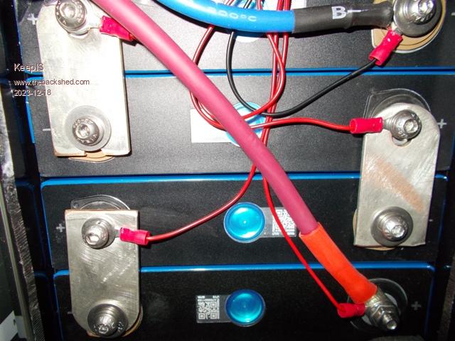 NANO:Inverter V 8.2ks - Linux AvrDude GUI script V4.1 |
||||
| KeepIS Guru Joined: 13/10/2014 Location: AustraliaPosts: 2139 |
I grabbed a 16S 200A BMS and an Active equalizer, I took 16 cells from one bank (4) batteries and managed to get all cell sense and balance leads correct first go for 54V out. I have not top balanced each cell yet. I decided to charge the 54v battery at 25A and slow the rate of charge if the Delta was more than 300mv, and just let the active balancer do its thing for now. Every cell appears to be fine, I will do a discharge / charge cycle and plot the real capacity when I get a chance – I have a tester for that. At the moment the 16 cell battery is running the home and workshop with the cell voltage variation across 16 two year old cells at 42mV. The second bank was in almost the same sorry state, they used the correct size Copper links this time, but again, some terminal holes were not deep enough with screws bottoming out without fully clamping the links. Lot of loss in the Link to terminal connections. I think I caught these just in time. BTW I did get a free replacement for the faulty dead unit. Apparently one cell had failed? I used a JUNCTEK Battery monitor to make an automated top balancer with relay cut out at a precise cell voltage, works brilliantly with a modified 40A 5V Adjustable PSU set to 3.6v and using the Terminal voltage sense lead and Over Voltage and over current relay cut-out from the Junctek. I’m also using a JUNCTEK BM for quick visual SOC and to protect the Batteries from a rare but not unheard of failure of the Solar Regulators going short from Input to output, (yes I know some expensive units have isolated outputs) the Charge input is isolated from the batteries via a Contactor with incorporated economizer, works brilliantly. I found two cases where the BMS fused the charge FETS from over voltage input due to the mentioned Solar reg short – results – 16 fried LiFePO4 cells. So I don’t fully trust the BMS isolation FETS, yes I know there are other BMS units that use a real relay or contactor, or have the control interface for them, but it is what it is, and this is simple and low cost for me to add, BTW my inverter also incorporates fully automated cap bank inrush pre-charge using the same big HV contactor, the inverter has timed mains transfer along with automated start stop or shutdown if selected. The 48V BMS was DELGREEN 200A 16S and their 16S Active balancer. Again there are haters of this brands, whatever, not interested in hearing it. I will agree that their WEB site sucks, they have limitations depending on your expectations, but they were at a reduced cost and up to half the price of the same unit sold in AU. I have a second unit coming to convert the final bank. The PC Software is ok, but it’s a kludge in having options for all models and features that don’t apply to most of the units I see people using. The Active balancer works well with the PC SW and the Phone app, however the Phone APP had the same Kludge of being very amateurish with every needless or unused tab available for every unit made, but nothing tailored to the BMS you are using. Once I had a handle on the way the PC and Phone APP worked with the Balancer and BMS (independently) I was able to work through all settings and makes sense of every unused option. In the end the SW is fine and not the horror story I was led to believe. It could be really good if they would listen to the complaints. I have seen posts of users complaining that the readings jump around and they are dismissed by others as not happening to them at all. Well - the PC app voltages and current jump around due to the way the SW is written, it appears to NOT return discharge and charge voltages in the same packet?? The SW shows charge and discharge current on the same Meter, but on each alternate read update. - So each data update is time shared if current is being drawn WTF? If no current is being drawn it look fine, if current is being drawn and you are not charging it look fine. Do both and it alternates I/O current on each update. Another complaint is the apparent inaccurate voltages between cells when the Balancer is running. Now one of the options from DALY is a combined package of BMS and external Balancer, and there is another that appears to have the Cell connection Loom spliced and split for the BMS and Balancer connectors. This will make the problem worse and the expiation is simple. The Balancer is reading the cell voltage at the end of the longish wires running from each cell terminal, if you are drawing 1A in balance current, you will be measuring the voltage drop across the cables, they will appear to be inaccurate, if you splice into the BMS loom, you will also cause the BMS cell voltage indication to sag and dance about for the same reason. As the cell voltage sense wires connect to the Positive terminals only, reading cell voltage across these terminals will also include any voltage drop due to bad inter cell connection of the Link Bars, obviously only under load, but everything needs to be checked under load to minimize these problems or cell balance won't work correctly. Currently every connection is less then .07mv @ 45A. I still need to go through the Links though. BTW I was two short in the build and ended up making two from some copper sheet I have, made the same way as the new EVE link bars with two thinner bars together which are more flexible, and on those two links I read 0mv @ 45A. I found the Balancer readouts to be very accurate, the BMS was about 14mV out, not bad. FYI - I have an accurate voltage source to calibrate my meters, I find most of the meters and readouts available on line should be correctly renamed to - Random Number Generators. 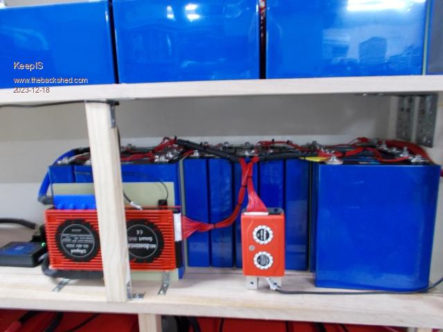 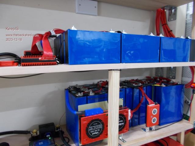 This is the load, 43A @ 53v and 42A @ 12V using a combination of series or parallel or single connection. That’s a couple of KW at 50 volts. 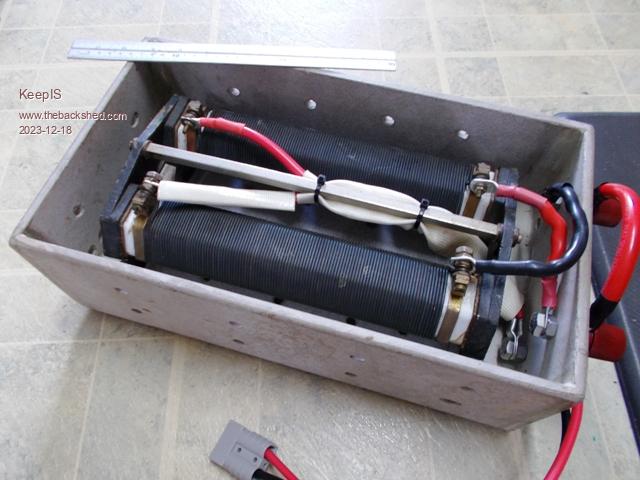 . Edited 2023-12-18 11:46 by KeepIS NANO:Inverter V 8.2ks - Linux AvrDude GUI script V4.1 |
||||
Revlac Guru Joined: 31/12/2016 Location: AustraliaPosts: 1257 |
Good Bit of reading, I got all lost in it a few times, but will have ago.  I will post some findings and photos in my own thread because I had the very same thing happen with some cells bought from Ali...will not do that again. I wouldn't look to deep into that. Yes that should be fine, I did mine that way, they were a little out of balance and with the Daly 16S 200A 30Ma ballancer it tooks weeks, then I pushed the bulk charge to 56v and its been good ever since. I don't think there is a lot of difference between the Daly and the DELGREEN last time I looked, lately I have been looking at getting A JK with 2amp active balancer. Cheers Aaron Off The Grid |
||||
| KeepIS Guru Joined: 13/10/2014 Location: AustraliaPosts: 2139 |
Hi Aaron, yes looks like the same factory for the BMS. The inbuilt BMS 30ma passive balancer would take forever, the 1A external Active balancer is working pretty quickly. I could have turned off the inbuilt passive balancer but instead set it to only work at the float charged voltage. Apart from overcharging, aggressive charge and discharge current and running it flat, the other way to degrade a LiFePO4 cell is to leave it sit "near" 100% charge for an extended length of time, UNLESS it's being cycle charged and discharged each day, which is what LiFePO4 was made for. They start to degrade sitting above 70%, obviously for many months or more. When you look at the chemistry and the latest scans of the efficiency degradation pathways you tend to think about it a little more, it appears to be an ongoing evolution in best practice for longer LiFePO4 battery life. In my case I'm holding the reserved banks at 90% as they get a cycle every 3 days, the data on the level of cell degradation from 12 months of near 100% is not nice to see if you have cells of suspect quality, which is unknown in my case. So I have erred on the side of caution from day one, and it has been two years so there will likely be some age related drop as well, I will soon find out when I get around to testing. . NANO:Inverter V 8.2ks - Linux AvrDude GUI script V4.1 |
||||
| Murphy's friend Guru Joined: 04/10/2019 Location: AustraliaPosts: 674 |
Looking at your first picture, I would not be happy with those cell links. Mine have a hump (like a speed hump) in the middle, presumably to compensate for any temperature related dimensional changes between the firmly clamped terminal bolts. |
||||
| KeepIS Guru Joined: 13/10/2014 Location: AustraliaPosts: 2139 |
Hi Klaus, they looked even worse when I first extracted the cells from of the case. I will be making my own to replace all of these. The two Links I made and tested the other day work beautifully. All four batteries were assembled the same, it looks like a supply shortage for that batch of batteries back then. The other sets were bought about 2 months later and use the same thick high current solid links, but correctly sized. I think the hump in the links are also there for the expected dimensional changes in the Prismatic cell Posts and case swelling, more or less over their life time, I think most of the initial swelling happens at the factory from the initial charge discharge cycles for grading etc, if not abused they appear to have little change after that. I guess it also depend on the quality of the cells and other environmental / load / charge conditions. None of these cells were clamped and I'm not doing that now in light of the way I use them, I leave about 4mm space between all cells when I assemble the cells into the desired configuration. I also have a 48V 16 cell EVE bank which uses the copper links you describe, these are two layer links with some flex, very nice units and the cells have solid meaty quality terminals. EDIT: Also looking at the picture notice the mismatch of washers and spring washers, along with only partial contact with the full cell terminal surface due to the hacking of the links. . Edited 2023-12-18 19:04 by KeepIS NANO:Inverter V 8.2ks - Linux AvrDude GUI script V4.1 |
||||
| Revlac Guru Joined: 31/12/2016 Location: AustraliaPosts: 1257 |
There is a LiFePO4 QR scanner app that sometimes works, no guaranties, it Didn't work on the Ganfeng cells I have, until I typed in the code then it worked, apparently the scanner might not work on reflective silver QR codes until its converted to a black and white photo, don't know haven't tried that. Cheers Aaron Off The Grid |
||||
| Murphy's friend Guru Joined: 04/10/2019 Location: AustraliaPosts: 674 |
Hi Mike, My main battery bank is made from these: www.ev-power.com.au/product/ev12v200ah/ See how they are steel strapped between alu end plates, no chance of swelling there. I have 8 of these 12V (nom) modules, made up into 2 x 48V battery banks. They have Delgreen balancers fitted. These banks plus my old 16 cell Winston 200Ah bank supply all my power requirements. They are not pampered, often subjected to charging of 100A+ or similar discharge (shorter duration). But rarely discharged below 75%. They are holding up well so far. I did look at the much cheaper battery packs but am glad I chose the more expensive ones though, being from a local supplier, I could pick them up and save shipping costs. |
||||
| KeepIS Guru Joined: 13/10/2014 Location: AustraliaPosts: 2139 |
Thanks for that, well the cells are genuine EVE cells made on 23/06/2020 - 173.0Ah, so apart from the inept construction they should at least be of reasonable build quality. NANO:Inverter V 8.2ks - Linux AvrDude GUI script V4.1 |
||||
| KeepIS Guru Joined: 13/10/2014 Location: AustraliaPosts: 2139 |
Hi Klaus, they look good, nice have a place within easy driving distance. I'm pulling apart another four batteries today, I'm going to top charge the 16 sells to see how that effects cell balance on the first cycle, I'll put one on the Tester and see what the real AH is at this point in time. NANO:Inverter V 8.2ks - Linux AvrDude GUI script V4.1 |
||||
| KeepIS Guru Joined: 13/10/2014 Location: AustraliaPosts: 2139 |
Just tested the 16 cells from four of the 12v batteries converted over to the first 48v battery configuration. 90% SOC Property running on the Inverter and this one battery. Big workshop Bandsaw powered up - 400A peak DC startup surge. That current surge was on top of all of the house and workshop standard running loads. Instant startup, same as if it was on Mains power. No trip no hesitation  Now onto the next four 12v battery conversion. Things are starting to look good. NANO:Inverter V 8.2ks - Linux AvrDude GUI script V4.1 |
||||
| KeepIS Guru Joined: 13/10/2014 Location: AustraliaPosts: 2139 |
About a week ago after I found the construction problem in the 12V batteries, I cutout the end of each battery to access the Cell terminals and attempt to band-aid the problems to see if the cells were damaged. You can see some big washers and even stacked washers to get the tension onto the Link bars which were unable to be clamped correctly due to insufficient screw hole depth, they were drilled incorrectly and there is no way I'm going to attempt to drill the posts. There is enough thread to get good tension if you stop the screw from bottoming out. This is the second 4 x 12v bank I'm about pull down for another 16 EVE cells. The Anderson connectors are where I plug in the Active Equalizer and also where individual 12v batteries could be adjusted to keep the bank in balance if needed. The Meters quickly added to keep an eye in each bank as I load tested and High current charged them during the tests, also monitored each cell during the process looking for any obviously bad cells. 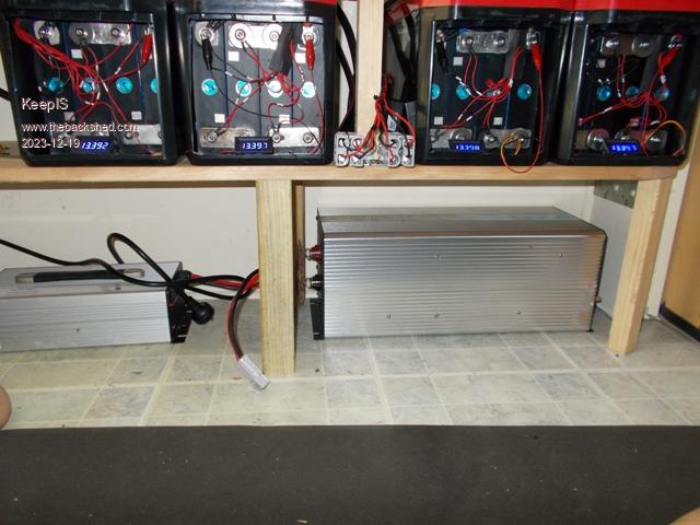 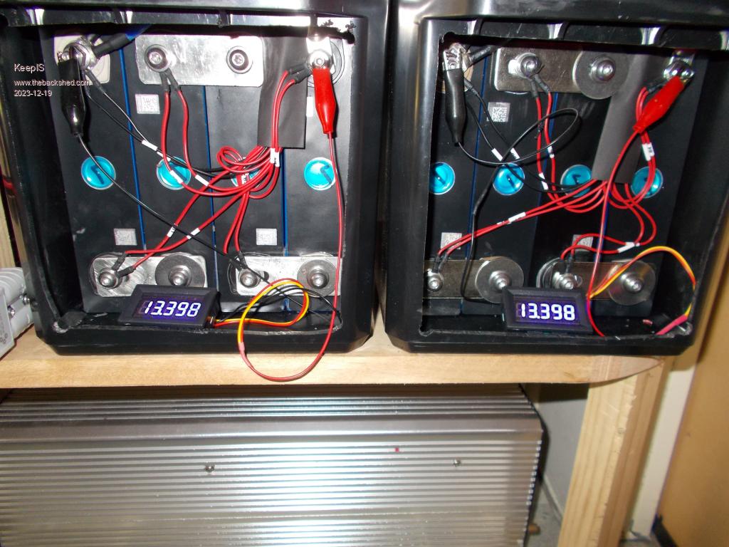 Edited 2023-12-19 10:14 by KeepIS NANO:Inverter V 8.2ks - Linux AvrDude GUI script V4.1 |
||||
| KeepIS Guru Joined: 13/10/2014 Location: AustraliaPosts: 2139 |
Says Dual BMS - not expecting to find two really small units, sigh! 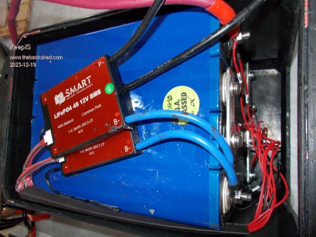 NANO:Inverter V 8.2ks - Linux AvrDude GUI script V4.1 |
||||
| Revlac Guru Joined: 31/12/2016 Location: AustraliaPosts: 1257 |
Ah, so that's what they look like, I remember Giant advertising them. Actually that was the brand name.  Edited 2023-12-19 12:21 by Revlac Cheers Aaron Off The Grid |
||||
| KeepIS Guru Joined: 13/10/2014 Location: AustraliaPosts: 2139 |
It's not the brand you mentioned, but as these batteries are a few years old, I don't want to cause any harm to small businesses that would have been doing it tough back then, and are likely having more trouble now with the way they are being secretly backhanded by various groups of clowns. But even after getting the connection links in a low loss working state, this bank did not have a hope of starting the big BandSaw, just trips with low voltage. The 48V pack built from the same cells now has no trouble. I would likely put that down to the extra voltage drop across Four BMS, 4 sets of positive battery terminal to cell connections, and the smaller gauge cables used. They simply cannot handle 300ms 400A DC inrush current peaks from the AC load on the inverter. They would definitely drop below the LV cutout, I'm assuming that the BMS is not spitting the dummy, but who knows, and frankly I could care less as they will no longer exist after I rip their guts out . Edited 2023-12-19 13:08 by KeepIS NANO:Inverter V 8.2ks - Linux AvrDude GUI script V4.1 |
||||
| phil99 Guru Joined: 11/02/2018 Location: AustraliaPosts: 3213 |
You may be thinking this already, but perhaps get rid of the cases and BMS units. Link all the cells in one chain with thick links and cables. If they survive the Bandsaw test then it may be worth adding your own proper BMS and getting some more mileage from them. |
||||
| KeepIS Guru Joined: 13/10/2014 Location: AustraliaPosts: 2139 |
Hi Phil, if you look at the photos in post three you will see this is exactly what I have done, 3rd post shows 16 of these pulled cells in series and a 200A 16S BMS with 1A Active balancer. Working perfectly. These last photos are from the next set that I'm converting into another 48V battery. Which is why the first set now pass the Bandsaw test on their own, normally when starting equipment like this I have two or three banks (if same SOC) switched in parallel for the inrush current startup. . NANO:Inverter V 8.2ks - Linux AvrDude GUI script V4.1 |
||||
| KeepIS Guru Joined: 13/10/2014 Location: AustraliaPosts: 2139 |
Found one with the bottom protection cover partly unglued, that exposes the metal case which is also the Positive terminal of the battery. The active metal case of this style of LiFePO4 is why I questioned the decision to just lay 4 of these cells together and wrap them in tape, that blue metal cover is pretty thin, if a pair of cases punctured through for any reason that's two batteries shorted. These 12v batteries were also targeted at off road vans and 4WD solar. Maybe I'm just been paranoid  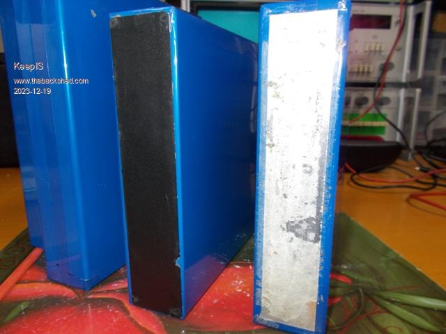 NANO:Inverter V 8.2ks - Linux AvrDude GUI script V4.1 |
||||
| KeepIS Guru Joined: 13/10/2014 Location: AustraliaPosts: 2139 |
The cells shown above appear to be fake, the barcode is almost a faded pretend bar code square, there are only 12 digits and the reader does not identify them either by scan or code input, merely giving a suggestion of fake from two possible sources that I have never heard of. Still, they appear to work, I will put one cell on the tester overnight and see what it comes out at. What fun! NANO:Inverter V 8.2ks - Linux AvrDude GUI script V4.1 |
||||
| Page 1 of 4 |
|||||
| The Back Shed's forum code is written, and hosted, in Australia. | © JAQ Software 2026 |
