
|
|
Forum Index : Solar : Battery problems and LiFePO4
| Author | Message | ||||
| KeepIS Guru Joined: 13/10/2014 Location: AustraliaPosts: 1387 |
I tested one of the clone cells, I set the same discharge rate as the spec sheet for the 4 cell 12 battery that this cell came from. This was just a rough test to give me a ball park idea of the state of the cell. The difference in my test was: Battery was only at 90% SOC I set the tester to stop discharging at 3.00V The 3 year old 170Ah cell at 90% charge gave 149Ah which is roughly 165Ah allowing for SOC. So after a 15 hour at a constant 10A discharge the 170AH cell was 165Ah @ 3V I will do another Cell test from 100% SOC and at a higher discharge rate today. FYI Here is the discharge curve. Apology for poor quality conversion. 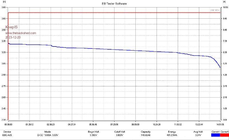 . It's all too hard. Mike. |
||||
Revlac Guru Joined: 31/12/2016 Location: AustraliaPosts: 961 |
You might have seen the off-grid-garage and how Andy tests these cells, the curve you have looks ok, but these do change a little between manufactures.  Cheers Aaron Off The Grid |
||||
| KeepIS Guru Joined: 13/10/2014 Location: AustraliaPosts: 1387 |
I found these on line while looking for a low cost charger, I would have liked the big unit they make but shipping was stupid, and even then there are charge limitations. The little unit I have has low charge capability, but I'm not interested in that now as I have a High current Cell charger and just finishing off a 56V high current charger. But the small unit is low cost and free shipping, I just couldn't resist, and it also measures cell internal resistance, saves me mucking around each time. BTW the Int Cell R was in spec  It's all too hard. Mike. |
||||
| KeepIS Guru Joined: 13/10/2014 Location: AustraliaPosts: 1387 |
Last of the other 4 batteries with Fake EVE cells. What I'm seeing is poor fitting of the top and bottom insulator strips, some look really bad because they were covered with rubber poured compound and it leached under the cover strips and the Link bars, real mess. Again, 4 cells are plastic wrapped together, the only thing between the Battery Positive metal case of each battery is a very thin plastic membrane. Here is one cell with the positive case exposed, in an off road vehicle and associated vibrating environment, I still worry about a problem a few years down the track, oh and the molding rubber holding the battery in place simply pulls away from the battery and case if battery happens to be mounted on it's side, or gets any heavy bouncing force in the vehicle. Anyway enough of that, not my problem any more. 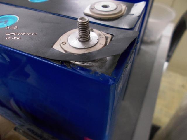 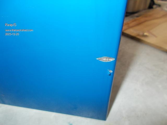 It's all too hard. Mike. |
||||
| KeepIS Guru Joined: 13/10/2014 Location: AustraliaPosts: 1387 |
Well it's just as well I tested the Current and voltage from EBC- Battery tester. The Discharge Current was 12.6A NOT 10A on the first Battery test, that means the first battery and graph that I posted above was running at its rated AH. I realized something was wrong when I repeated the test at 20A, the higher current makes the initial cell float chg drops straight away and gives a must smoother curve at the start. Tested at 20A Discharge the battery measured 178Ah ??? Tested the 20A current draw and it was actually less than 20A at 19.7A which brings it back to the correct value AH for the Cell 170Ah. Trying to calibrate EBC Tester is a problem and it appears there is a lot of frustration on line about calibrate - anyway I managed to get the 20A discharge calibrated so that's the main thing. So two of the clone Cells I tested are virtually like new. There is hope for the rest. I'm about to make around 60 Copper cell links myself, the plated ones that came with the cells are needlessly thick and make it hard to remove all R-loss. The two layer copper units I made and tested have virtually zero loss and less clamping force needed. I will just check them occasionally until they have set in. . Edited 2023-12-21 14:31 by KeepIS It's all too hard. Mike. |
||||
| Revlac Guru Joined: 31/12/2016 Location: AustraliaPosts: 961 |
I made up a jig to bend the copper bars, just sits in a vice and wind it up and they all had the some speed hump shape, I put heat shrink on them afterwards. Cheers Aaron Off The Grid |
||||
| KeepIS Guru Joined: 13/10/2014 Location: AustraliaPosts: 1387 |
I finally got another bank built and installed with BMS and active balancer. These are fake EVE cells. 5 of these cells will go out of balance by around 200mv once charging gets above 3.5v per cell. I spent some time top balancing them, it did improve but they will never match the others in the bank. As long as one keeps away from that hockey stick part of the curve, these cells do not go over voltage, even without the active balancer. Interestingly, it is only above 3.5v that they really differ. Once you draw current and the "no current" float voltage instantly drops, as it should, the cells will track withing 18mv even at 60A discharge. They also track on high current charge without any assist from the Active Balancer. So I'm going to cycle them a few times and see how they go. I have some spare cells if needed, just a time consuming pain to test and match them. Below: These are the Genuine EVE cells I bought - the only time the active balancer came on was when I was using it to top balance them, after that. it's virtually not needed. 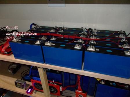 Below: The 1st converted 4 x 12v battery's. These were "surprisingly" genuine EVE cells. I still have to change the Cell Links over to the ones I made, which are far superior to these thick hardened copper links. 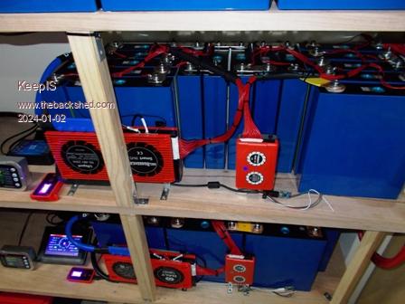 Below: The 2nd lot of 12V batteries converted to 48V, I finished these yesterday. They have my DIY links and I'm waiting for the screw in studs to arrive so I can ditch the stupid terminal screws. 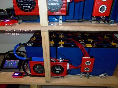 It's all too hard. Mike. |
||||
| KeepIS Guru Joined: 13/10/2014 Location: AustraliaPosts: 1387 |
During the course of the morning, despite pouring rain, dark overcast sky, and only half of the solar panels in use, I was able to generate just under 1KW of solar. That was enough to keep everything running on the inverter and hold the last 48v battery bank at the current level. However when we were briefly running at close to 3kW I got a disconnect / reconnect cycle from the Inverter, then a second cycle, so I switched to Mains priority. The Auto Transfer switch is able to switch seamlessly between Mains AC and Inverter AC, for obvious reasons you would NOT want that cycle repeating for to long. The DALY BMS with HW versions BMS-ST103-309E have Alarm data which it's accessed via the PC SW and also saved to disk in the History Data directory. This is such a handy feature and it appears that only the CAN/Rs458 models have this capability. It showed: Time: 2/01/2024 11:34 Err: ErrCellV_Low_LV2 Voltage: 52.6V Current: -48.6A Chg MOS: ON DisChg MOS: OFF Max CellV: 3.316 Cell 5 Min CellV 2.956 Cell 6 The Discharge MOSFET disconnected the DC supply to the Inverter, cloudy overcast and rainy day meant the Solar Charger could not keep the Inverter running (as it normally can) and this could have gone unnoticed until nightfall. Now I was sure I had checked and double checked every terminal on the 16 Cells, so I set the Low V cutout in the BMS even lower, then switched the ATS back to Solar priority to investigate. The Inverter took the now 2.5kW load without indication that anything had switched (seamless) and I got my favorite tool that won't accidentally short out a Cell terminal "My Finger" and felt the terminals and Link between cells 5 and 6, the Link was warm  . Some dumbarse had only finger tightened this one nut . Some dumbarse had only finger tightened this one nut  While on the subject of the DALY BMS - I have 3 of these and they all show random stupid values of charge and Discharge Current, but only when the Inverter is running, I'm now convinced that the Current Sensor in the BMS is not filtered correctly for HF/LF noise. NO, changing the Fudge factor value in the DALY BMS for noise does not work - that is really only for noise around zero current. This problem does effect the Battery Capacity calculations. Fortunately the 400A JUNCTEK current shunt and battery capacity Meter is 100% noise immune and 100% accurate even down to a few mA, and it's always on so no need for an APP, although it also has Bluetooth and a phone APP if needed. Below: The Inverter still running perfectly after it one an only hiccup a few months back. [Caused by and underrated Diode] 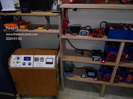 You can see the JUNCTEK LCD displays on each shelf, these display screens will be incorporated into a single panel between the top and middle shelf once the battery modifications are finished. I have two 5 port USB hubs supporting 3 Active Balancers and 3 BMS units running back to the Main PC via a single powered extension 5m USB cable, a small Tablet can also use the single USB output locally. The wires showing next to the Active balancers, seen in the previous photos, are some RS252 to USB converters that I'm making up and are temporarily plugged into the UART sockets on the Active balancers. This obviously allows one PC program to access any of the units on the fly. . Edited 2024-01-02 14:41 by KeepIS It's all too hard. Mike. |
||||
| Revlac Guru Joined: 31/12/2016 Location: AustraliaPosts: 961 |
Hi Mike, That's looking good, I have solid copper bars on my cells (recycled from a large transformer) thats all I had at the time and put a generous size hump in the middle of the bars, and they do flex a little by hand. I'm sure you will check those links again in a year orso, seems to be the way with some connections. Out of the 3 DALY BMS units I have 1 of the 2 200A always calculates the SOC lower than the other one, even when the charge controller was changed and extended the battery cable by 2.5m. I checked today and the 150A BMS in the shed has CAN/485 connection, the 2x200A BMS at the house do not have that connection available for some reason. When everything is working well there is very little (No Work) for the BMS to do...... when there is plenty of solar and plenty of battery capacity left by the next morning.... I will have to put a JUNCTEK on the shopping list.  Cheers Aaron Off The Grid |
||||
| KeepIS Guru Joined: 13/10/2014 Location: AustraliaPosts: 1387 |
Hi Aaron, Yep, periodically checking terminal bolts/screws for correct tension is something I do over the complete system, especially high current connections. You could write a small book about the myriad of pathways that lead to loss of connection integrity. An added problem that I have is caused by the "clowns" who tapped the cell terminal posts, they did not tap all of them perpendicular to the post surface. DALY apparently use 3 different types of chip sets in these devices depending on the configuration. The trouble is the web site, it has so many pages for the same looking device with bad English interpretation, it's so utterly dumb that you can go around in circles trying to actually confirm what configuration the one you are looking at actually supports. Especially if you are new to this and not aware of the Chip set lottery. This is the link I use, the BMS has parallel port, CAN/RS485, Key and DI/O with optional addons like Active EQ and Parallel balance. DALY Link I also order a couple of RS485 to USB leads from them to connect the Balancer and BMS via their RS485 com ports as it can wake the BMS from PC software connection activity, the standard UART port cannot, that also leaves the UART ports available for the DALY Bluetooth dongle if required. BTW thanks for that link, I found his tear down and hack of the BMS about 3 weeks ago  . Edited 2024-01-03 08:50 by KeepIS It's all too hard. Mike. |
||||
| KeepIS Guru Joined: 13/10/2014 Location: AustraliaPosts: 1387 |
Well, a few overnight cycles down to 50% SOC and back up to 3.45v per cell in the morning and all cells are now tracking within 15mv per Cell at charging currents holding between 37A to 50A. The Active balancer came on couple of times for around 10 to 20 seconds this morning and that's all. Looking good. I actually have enough Cells left to make a third 170AH 48V battery. That will be interesting as it will have four new cells combined with twelve three year old cells. The four new cells are from a 12v battery that I was given as a replacement for the faulty battery I returned out of another 4 x 12v battery bank. BTW: The following may or may not be of interest to anyone but here it is: The BMS Hardware codes and BMS SW version. BMS hardware version number: The hardware chip scheme used in the BMS has thirteen characters. The First three digits = BMS. BMS-ST103-309E The middle is MCU: MCU Abbreviation MCU Full Name ST103 STM32F103RBT6 ST030 STM32F030C8T6 GD230 GD32E230C8T6 Last four digits are AFE: AFE Abbreviation AFE Full Name 309E SH367309 303E SH367303 DVCE MT DVC 9818 9818 The device running in AFE operation mode in my BMS-ST103-309E is an SH367309: The SH367309 is an analog front-end IC for lithium battery BMS. It is suitable for lithium battery packs with a total voltage of no higher than 70V. In AFE mode the SH367309 can be used with the MCU to manage the lithium battery pack, supports all protection. The SH367309 has Integrated VADC for cell voltage measurements, temperature measurements and current measurement; Integrated CADC for current measurement, used to count the remaining capacity; Integrated EEPROM, used to save adjustable parameters such as protection threshold and delay; Integrated TWI communication. BMS Software Version: Total of thirteen characters, the first two digits represent the chip solution, the middle represents the release date, the last four digits are reserved, and the default represents the project code. 11_231110_001T 1st digit: 1: STM32F103 2: STM32F030 3: GD32E230 2nd digit of the item number: 1: 309 2: 303 3: 9818 4: DVC FYI the SH367309 has: A 13-bit VADC for Cell Voltage, Temperature and Current Measurements. Measurement Frequency: 10Hz - 16 Channels for Cell Voltage Measurements - 1 Channel for Current Measurement - 3 Channels For Temperature Measurements 1 CADC for Current Measurement, 16 bit Σ-Δ analog-to-digital measurement, 4Hz measurement frequency, 1 channel differential input. . Edited 2024-01-04 14:50 by KeepIS It's all too hard. Mike. |
||||
| Revlac Guru Joined: 31/12/2016 Location: AustraliaPosts: 961 |
Any thoughts on covering the cell terminals? I had thought of printing some terminal covers a few times but haven't done yet, would have been great to have them before I assembled the pack, had to put plastic sheet either side of the cells I was bolting the buss bars onto. Found a cable for the BMS its a UART to USB, there is another cable somewhere but its still playing Hide & Seek, Tried Sinowealth BMS Toll on the PC but its not working yet. The DalyBmsMonitorV1.1.6 is working. This is on the large white batteries in the shed, .png) Some of the setting's don't match the BMS phone app. Footnote added 2024-01-08 18:21 by Revlac Updated to the later version, much better. Cheers Aaron Off The Grid |
||||
| KeepIS Guru Joined: 13/10/2014 Location: AustraliaPosts: 1387 |
There is a later version V2.1.9, it works a lot better and has all English text parameters. You can see by the HD version they have a lot of different Chip Sets going back. The ones I posted are likely the main build now up to 16S, but smaller devices will obviously be different, as will the higher voltage BMS units. From memory, the Phone APP lumps some of the settings into different tabs. And I don't think the Phone APP has the Level 2 parameter settings? The latest PC V2.1.8 also has the Active EQ Tab, like the newer Phone APP, when either are connected to the BMS, that tab partly reflects the Passive 35ma balancer in the BMS. However when they are connected to the Active EQ module, only the Data screen (no current reading) and the Active EQ screens are valid and will correctly set and read the Active EQ module status. There are a lot of settings I have changed, starting with the absurdity of -45 deg operation temp. It's all too hard. Mike. |
||||
| KeepIS Guru Joined: 13/10/2014 Location: AustraliaPosts: 1387 |
On the subject of covering, I plan on having a clear Polycarbonate covers over the top of each battery, I've used that a lot in the past, and vented doors on the front of the battery shelf enclosure. I have a bit of wiring to redo and the JUNCTEC displays to mount, I'm trying to make everything neat and logical so "almost" anyone can figure out the system layout and operation.  It's all too hard. Mike. |
||||
| KeepIS Guru Joined: 13/10/2014 Location: AustraliaPosts: 1387 |
I decided to pull the 4 Cells from the new replacement 12v LFP battery. There is some difference compared to the 3 year old units I stripped. 1:They now have a separator sheet between each cell - finally! 2: All terminals are fitted with studs. 3: Link Plates are now the correct size. Looks like they now import the Cells assembled as a 12V unit encased in a shrink wrap plastic covering with Chinese writing and a random number with AH capacity on a stick on label. The Battery case was still 1/4 filled with a rubber solution that does not fully harden around the submerged terminals, it's liquid around the terminals and has migrated under the Link plates, it causes the glued cell end cover strips to come away anywhere they were submerged in the goo. The Cells are the same clone cells, underneath the top (terminal) cell cove strips, one finds the original engraved Barcode has been scoured out, a fake stamped barcode is in a different location to match the glued on top cover sheet cutouts. Same as the older cells. I noticed a very slight dent or scratch on each of them, maybe they got a good price from a bulk scratch and dent sale Anyway, all cleaned up and ready to be assembled with the other 12 cells into the last 48V battery conversion. The first two 48v conversions are running great now. . Edited 2024-01-08 15:18 by KeepIS It's all too hard. Mike. |
||||
| KeepIS Guru Joined: 13/10/2014 Location: AustraliaPosts: 1387 |
During the course of looking for serial data command info for the DALY BMS, I was reading about the problems being reported by users of the DALY BMS, and apparently these so called failures are one of the reasons some changed to another brand of BMS. Even some of the DOA complaints looked like possible user error. There are complaints of incorrect cell balance voltages, and claims that when measured with their trusty meter, the meter said it was all good, but looking at the typical steps taken to find the problem, not once did I see the obvious question, or the correct way to test and measure for this apparent error. Swapping the BMS would likely fix the error by default, but there is no way to know. Now I agree, the software is still a bit amateurish, so many models to be catered for with the same program - dumb. There is no way to really set it up for the correct charging mode for LiFePO4, but this is the same for almost all the affordable BMS units out there, so I'm not going to change because of reported user errors of which some appear to be dubious. I see a lot of users making mistakes early on with settings and construction, and the crap excuse for a manual may be to blame in some cases. Anyway, I decided to experiment with making the BMS do something that a BMS is not meant to, but humor me, it revealed a hidden problem and possible failure mode. I configured the BMS to switch off the charge MOS above a lower specified voltage, this voltage should be around 90% of charge, by programming the Solar chargers to run at 1 volt higher, it should cause the batteries to be "SEMI" isolated from the DC supply system, unless pulled down by a big load on the Solar charges or Solar output drops off. The Four Solar chargers I have would, and they can with ease, power the inverter, I have plenty of Solar. So once the battery is at roughly 90% and the Charge MOS switches off, there would be minimal small voltage cycling of the battery, which is bad for LFP. It did work, and dumping a 2kW load onto the system already powering the Home, workshop with Shed AriCon, does not cause a sag in the voltage from the Chargers, so the Battery MOS does not reconnect. However, one must realize that there remains the possibility a momentary high charge current if the charge MOS reconnects with the Solar charges not loaded down and 1V higher than the Batteries - which had been disconnected for a few hours. Like I said just a crude "what if" test. It highlighted a potential problem, and I would assume for most BMS devices using physical external communication connections cables to anything that shares a common battery Negative connection. Think of four BMS devices, each with a cabled COMS link back to a single display and sensor device, and this device would likely have a connection to Inverter Neg / system ground. Even without that connection, each BMS is connected to the system Neg Rail and one has an overcharge MOS switched off, the four are plugged into the same monitor device, so all BMS are connected to a common ground via coms leads and BMS negative leads. The Common mode BMS with only Negative battery switching is going to partly isolate the Negative terminal of its battery on charge over-volt-trip. But the coms lead shares the common Negative ground of the BMS (battery NEG terminal). If the Charge MOS is off, the coms lead now becomes a Negative connection between BMS Battery Negative connection and the BMS connection to the System (load) negative rail, bypassing the MOS. What could possibly go wrong! Anyway, I'm going to program a micro to correctly disconnect the Positive lead of the batteries when the correct charge voltage and charge tail current conditions are intelligently met - and reconnect when the SOC has dropped to a predetermined lower level. I have an idea for a fail safe way to pull current instantly from the battery bank under high transient load demands, and it would allow the use of high voltage high current electric Vehicle power solenoids instead of FETS if desired, I've been using these solenoids in the Inverter - fabulous devices and low power when enabled. I'm sure if I read this back it will sound confusing - so I won't  . Edited 2024-01-11 17:38 by KeepIS It's all too hard. Mike. |
||||
| Revlac Guru Joined: 31/12/2016 Location: AustraliaPosts: 961 |
The DALY active equaliser arrived today, including the Free Gift "wiring harness" that is essential for it work, the wires are going to need extending to suit the batteries in the shed, might get to that next week. I read a few of those complaints in places, plenty of user error, and not just with the BMS but other system parts as well, I know the installation manual I was given was a bit different instruction to another one for the same BMS. Having done this quite a few times because the shed batteries (white plastic cells) get a bit out of whack, manages to take a photo of the inverters usage the charge controller input and the BMS CHG MOS turned off, all kept running without issue apart from the high cell voltage (set well below usual) that triggered the protection mode, there was nothing to pull that cell voltage back down so it could sit there for some time, or until I give the inverter some extra load that the Charge controller Couldn't keep up with because it is so slow to respond to loads, then the cell voltage is pulled back down and the charge MOS is then switched back on. How I see it with the Charge MOS off, the BMS is like a big Diode and the battery is still accessible to the loads when required. Hmm, I wonder if that makes any sense. Also when the charge mos switches off it reads or triggers 100% SOC, probably some other settings going on, most of them are still set at default. I will say that the other 2 systems on the house that are setup properly haven't had to trigger any safety condition and likely wouldn't for years to come, hopefully. I wonder is s current sensor on the small black wire would pick this up? Thats Actually a good point, But I had the idea the other way round, disconnect instead of reconnect.....I'm well past my last cup of coffee and my brains.  Edited 2024-01-11 20:45 by Revlac Cheers Aaron Off The Grid |
||||
| KeepIS Guru Joined: 13/10/2014 Location: AustraliaPosts: 1387 |
That is how I see it, likely the body diodes. Edit: Of course it is, and utilizing FET body diodes as part of the Charge/Discharge switching design. The change to set 100% trigger is the pack-voltage setting, obviously they want you to set that trigger point to what might be a 100% charge, which is in reality a very rough guess. In my case, the cell voltage trip is set to 3.5v and the pack voltage is set to trip when each cell is 3.4v, so the battery pack trip is 54.4v. The cell voltage should normally never trip in mine, only the pack voltage. Solar charge voltage is set to 55.4v (1v above the Pack MOS trip) so there is no short term cycling, and any slight sag will not cycle the MOS switch. I've had it running like this all day, once batteries were 3.4v per cell, the charge MOS switched off and only came on twice for a few seconds the rest of the day. It smoothly switched on as the sun went down. That's two 48V batteries running in parallel and tracking each other perfectly with their respective BMS MOS switching. Basically, once the charge MOS switches off in each BMS the battery banks spend the next 7 hours disconnected from the charging. It requires Charge controllers that don't over-voltage with sudden load disconnects or load variations. An Inverter that had good CAPS and does not rely on the low impedance of a battery source for its transient response, and one that has a toriod wound for a wide DC voltage input range to hold good AC voltage regulation under heavy load and DC sag, without stress. I use four 60A Make Sky Blue chargers (lot of people rubbish them) I purchased these for $170 each 4 years ago and were a bargain IMHO, and have worked faultlessly. So now, onto the task of implementing it correctly for SOC tail current and charge cutoff. . Edited 2024-01-12 13:11 by KeepIS It's all too hard. Mike. |
||||
| KeepIS Guru Joined: 13/10/2014 Location: AustraliaPosts: 1387 |
Aaron, you may notice that some Cell voltages momentarily elevated during the Active balance process, you might have to raise Cell over voltage limit a tad to account for the Active balancer operation when one is added to the BMS. Obvious depends on how low you actually set your Cell O-V. You can have it trip and not actually see it. It appears that with Common mode MOS FET switching, one of the known issues of not having a fully bonded ground is with "some" communication IO. It's all too hard. Mike. |
||||
| KeepIS Guru Joined: 13/10/2014 Location: AustraliaPosts: 1387 |
Small update, I just went over the graphs for the past 24 hours and with the settings I'm using it's doing everything correctly. The individual battery banks are switching on/off correctly, when they do switch on, their charge currents are almost identical. The External battery capacity meters are tracking within 1% for each bank over that charge - discharge and recharge cycle. They matched the BMS SOC right up until each BMS OV trip set its SOC to 100%. The external SOC indicators were at 97%, they reached 99% after a few cycles at 28A each when the MOS charge switches turned on due some small discharges with falling Solar voltage, been raining most of the day here, Active balancers ran for a few cycles to trim a 38mv difference. This difference is actually getting less with each cycle as these pack of two and three year old mismatched cells seem to be settling in nicely. Our nightly power usage is very consistent, with two battery banks - 340Ah - the SOC is always around 75% in the morning in each battery before the Solar kicks in. Obviously by being in parallel they are virtually forced to track on discharge. . Edited 2024-01-12 16:22 by KeepIS It's all too hard. Mike. |
||||
