
|
|
Forum Index : Other Stuff : Axial-flux Generator
| Page 1 of 4 |
|||||
| Author | Message | ||||
MacGyver Guru Joined: 12/05/2009 Location: United StatesPosts: 1329 |
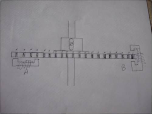
This is what I'm building and what I want to know is: Is this an "axial-flux generator or something else? The little dark squares are 1/4" neo-magnets press-fit into a solid aluminum plate. Each magnet in the series alternates ends. One is N/S and the next is S/N all the way around evenly spaced. The plate is attached to the main shaft at the hub with a set screw. The way I've drawn it, it looks like a slot on the hub. That is there because I was having a PM discussion with oztules about using a spring and flyweight mechanism to move the magnet rings to varying distances from the pick up coil(s) in plan "A". The idea was to start out with the magnets far away from the pick-up coils and as the speed of the twirling turbine increased, centripital force would throw the flyweights outboard and they in turn would slide the magnets down the shaft via bell cranks so the thing would be able to start with no load. The "B" scenario is there in case that's the true AxFx design instead of the "A" one. (I'm striking two birds with one blade here so to speak.) When I zero in on a design, this will be driven directly from the shaft of a VAWT. (VAWT stands for vertical-axis wind turbine for newbies). I redesigned the Lenz VAWT using both an inboard and outboard "cup" along the leading edge of each of three blades, which all circle the tower parallel to its axis. I did this after doing a wind-vector study of the Lenz to see if I could modify the already-good design to make it have more areas of "push" as each blade swings through its 360-degree, circular pathway. I think my modifications will be just the ticket. Of course, I've said stuff like that before only to wind up with egg on my face, so hide and watch! I finished constructing the blades yesterday and will attach them to the hub and shaft sometime today. I'll be posting pictures (likely in "Windmills" and not here in "Other Stuff") though as things progress. Right now, all I want to know is what to call what I'm building as far as the actual generator part is concerned. Nothing difficult is ever easy! Perhaps better stated in the words of Morgan Freeman, "Where there is no struggle, there is no progress!" Copeville, Texas |
||||
niall1 Senior Member Joined: 20/11/2008 Location: IrelandPosts: 331 |
hi Macgyver i,m confused ....B (to me) looks more like a radial design but using a core in the coil with the same magnetic poles appearing at both ends seems strange...A looks more axial but the core seems to complicate things again ... A this time sees an alternating flux through the core which seems to make more sense..... coils using alternating flux cores are very confusing to me ......one thing is i suspect it may cog heavily (feel very notchy in operation ) niall niall |
||||
| Dinges Senior Member Joined: 04/01/2008 Location: AlbaniaPosts: 510 |
[quote]This is what I'm building and what I want to know is: Is this an "axial-flux generator or something else?[/quote] Axial flux, as the magnetic fieldlines run parallel to the rotational axis as they leave the magnets. Keep in mind that NdFeB is brittle (basically a ceramical material). For a press fit, you need your materials to be ductile. Try press fitting an oversized steel pin in a hole in porcelain, and you'll get the idea. Press fits rely on the deformability of the materials. In your case, the aluminium may deform enough. But I'm not sure the magnets won't fracture as you try to press them in. I think I'd go for epoxy or another modern, good quality adhesive to fix the magnets into the aluminium rotor - much less that can go wrong that way. The shear stress of epoxies on properly prepared surfaces is very impresive; did some shear tests with NdFeB magnets in the past, and in most cases it was the nickel-NdFeB bond that failed: the nickel plating stayed in its place, held by the epoxy, whilst the rest of the magnet (bare NdFeB) sheared off. IIRC, it took over 1000N for a 15mm diameter magnet to move. Peter. |
||||
| niall1 Senior Member Joined: 20/11/2008 Location: IrelandPosts: 331 |
still confused ..... 
Peter ...i,d appreciate a lesson with regards to axial flux as against radial flux .....my heads hurting a bit now ... niall |
||||
| MacGyver Guru Joined: 12/05/2009 Location: United StatesPosts: 1329 |
[Quote=niall1]i,m confused ... Hey! Join the club. In both cases, there is an "N" pole and an "S" pole passing by the coil-pick-up ends. In the "A" model, the coils (I only showed one in my little drawing) are mounted under the ring of magnets. This was done to facilitate a spring-loaded sliding mechanism that was to work much the same as a governor on a steam engine. This arrangement allows the magnet ring to pull back from all the ferrous coil pick-up ends when it's not spinning and approach the coils only after gaining some momentum. I know Peter will likely not like that I am using springs against the wind, but I'm up for trying anyway. Color me consistent. In the "B" scenario, again, the coil pick-up ends each face an "N" and an "S" as the ring of magnets whirs through the gap, but these coils are mounted around the circumference of the thing and the windmill would have to start against a fully-cogged rotor. Since this is a VAWT, start-up torque is a joke, thus the "A" scenario. I'm thinking that the "A" model is more along the lines of an axial-flux machine, judging from all I've read about others' efforts, like on Scoraigwind, but I'm still not sure. Someone pinch me! I'm with you niall, I need some instruction here. [Quote=Dinges]For a press fit, you need your materials to be ductile. I realize the little magnets will explode in the arbor press, but I've done this successfully before, so I thought I'd give it another try. If all else fails, I can always machine a HDPE platform and press the little mags into that. It's pretty soft and forgiving. I chose this design, because it lends itself to keeping the magnets all lined up in a straight line and allows me to use off-the-shelf hardware for the most part. I'd like to stay from epoxy. The smell makes me want to puke. Nothing difficult is ever easy! Perhaps better stated in the words of Morgan Freeman, "Where there is no struggle, there is no progress!" Copeville, Texas |
||||
| niall1 Senior Member Joined: 20/11/2008 Location: IrelandPosts: 331 |
mmm....i see now how mags are aligned , that bit is clearer niall niall |
||||
| Dinges Senior Member Joined: 04/01/2008 Location: AlbaniaPosts: 510 |
[quote=Niall]i,d appreciate a lesson with regards to axial flux as against radial flux[/quote] In a radial flux alternator, the magnetic fieldlines leave the magnet surface radially, i.e. like the spokes on a bicycle wheel. In an axial flux alternator, the magnetic fieldlines leave the magnet surface axially, i.e. in the direction of the axis. Simplest way I can explain it without using figures. Peter. |
||||
| niall1 Senior Member Joined: 20/11/2008 Location: IrelandPosts: 331 |
erm ...i think it might be easier and quicker to beat the explanation into me... the rotational axis is the shaft ...so i see the parallel connection to A so for B the flux lines leave the magnet pole on one side and want to travel over the top of the rotor (through the core ) to the other side ...does this make b axial as well ?... regards niall later edit ......the penny finally fully drops ....  niall |
||||
| MacGyver Guru Joined: 12/05/2009 Location: United StatesPosts: 1329 |
niall1 According to what Peter has explained, I guess it's the way the magnets are aligned as to whether it's axial or radial. In my drawing, I am thinking, like you, that both "A" and "B" are axial generators; the axial-ness of it is determined by the magnet placement, which is the same in each. If this is wrong, I'm sure Peter will chime in and correct us, but that's my take on it so far. Now all I have to do is put all the parts together. I've finished building the blades and the hub and all the mounting parts, so I'll try to get everything together and snap a couple pics. I'm going to use the "A" configuration, as I want to be able to adjust the distance of the magnets from the pick-up coils using a home-made governor thingy I cooked up. I want my windmill to be able to start with no load and since it's a VAWT, it's more than merely on my "wish list"; starting no-load a necessity! I'll keep everyone in the loop. Nothing difficult is ever easy! Perhaps better stated in the words of Morgan Freeman, "Where there is no struggle, there is no progress!" Copeville, Texas |
||||
| MacGyver Guru Joined: 12/05/2009 Location: United StatesPosts: 1329 |
Dinges Take a look at my drawing, please. What do you think about mounting another pick-up loop suspended atop the magnets as a method to make a "return pathway" for the flux lines? From the side, it would look almost like the letter "O" elongated and with a slot at each end. I don't know if this would help generate more electricity or just cog like nobody's business. Edit: herbelagenen -- my "new word" of the week! (re-calculating) Nothing difficult is ever easy! Perhaps better stated in the words of Morgan Freeman, "Where there is no struggle, there is no progress!" Copeville, Texas |
||||
oztules Guru Joined: 26/07/2007 Location: AustraliaPosts: 1686 |
It will make power.... but gee it seems a hard way to do it. If you use lots of bits of paper and some colored felt tip pens and an afternoon, you may come up with a geometry that minimizes cogging. This will probably mean having to rectify each coil.... but that would be preferable to the spring and bell crank solution to startup...... Plan A will require the Al plate taking the full pull of the magnets. Single phase would rattle the thing fairly badly. If you solve the cogging (fiddle with the geometry), I would run with B as it balances the forces on the Al plate. This thing could use up a lot of little squirrel cage motors I suspect. ..........oztules Village idiot...or... just another hack out of his depth |
||||
| MacGyver Guru Joined: 12/05/2009 Location: United StatesPosts: 1329 |
Oz Tell me an easier way; I'm all ears! My concern with this thing is, as everyone already knows, the VAWT has no start-up torque. If all the permanent magnets are cozy, latched onto a pick-up coil, it'll take a mule to push the thing into motion. I had even thought of somehow mechanically moving all the little "C" coils by swinging them into position over the magnet-holding ring after the thing was up to speed. What I'm after is something simple, but the more I fiddle with this, the more complicated it seems to get. So, for starters, does the way I have the magnets pressed into that aluminum ring qualify it as an axial-flux generator? One step at a time at this stage. . . . . . . Mac Nothing difficult is ever easy! Perhaps better stated in the words of Morgan Freeman, "Where there is no struggle, there is no progress!" Copeville, Texas |
||||
| oztules Guru Joined: 26/07/2007 Location: AustraliaPosts: 1686 |
"Tell me an easier way; I'm all ears!"..... build a normal axial flux. It will be much better, with no drag, and no complexity at all.... won't be as interesting I guess, but will work much better. "So, for starters, does the way I have the magnets pressed into that aluminum ring qualify it as an axial-flux generator?" If the N and S poles are up and down then yes. ... and that appears to be the case here. If you can get enough motors to sacrifice themselves so that you can get quite a few of them around the disk, (setup B) you can then move them about ... with different inter motor/coil spacing so that they evenly attract the magnets... regardless of rotor position... cogging cancelled... end problem with startup (except for iron drag.... seems not to be as significant problem to the F&P fraternity. I say motor, as you will need to have the squirrel cage motors to get the laminates for the C coils. Dinges has written a great article somewhere on the net about decogging for motor rewinds, but the theory holds for this application too I suspect. If you can't solve the cogging in this fashion, then the complexity of your device will be overwhelming I think... like I said... your doing it the hard way. If you have used Ed Lenz's site to get ideas for the airfoils, then don't check out his axial flux stuff, or if you do....Don't try the layered windings. It makes it all too hard.... maybe this is what has encouraged you to take this road. Use this site as your guide. It takes not much more than a drill and a welder. .........oztules Village idiot...or... just another hack out of his depth |
||||
| Dinges Senior Member Joined: 04/01/2008 Location: AlbaniaPosts: 510 |
+1 on what Oztules said. Build a conventional dual-rotor axial flux alternator. Much simpler, no cogging, and guaranteed results. If you're using it to charge batteries, then it will spin freely until it reaches cut-in RPM. If you're using it for a heating load (yeah, right....) then it would require some simple electronics to not connect the load until it reaches a pre-determined RPM. Over the past five years that I've been reading windturbine forums, I've seen people complaining and thinking about the lack of suitable generators for a VAWT. I've never understood this - building the generator is the easy part of making a VAWT. Just increase turns to get your cut-in RPM to the low, desired value - presto. Of course, the lower the RPM, the smaller the power output for a given size of generator - that's life. I like elegant, simple designs. Complicating things is usually much easier than simplifying. Peter. (<-- lazy too - will gladly use an old motor if it means less work) |
||||
| MacGyver Guru Joined: 12/05/2009 Location: United StatesPosts: 1329 |
That sucks. I was writing a reply and somehow it disappeared! Okay, here I go again: Oz: Remember Homer Simpson's favorite word, "Doh!"? That's me when it comes to building a generator. Does the one shown on the Scoraigwind Web site have iron cores or is it merely a bunch of coils laid up in epoxy with the magnets whirring by? Did I miss something? (obviously!) If this would work better, I'd love not having to worry about it cogging. With no iron to hold up the show, this thing should never cog and would start, like you said, easily and not meet any resistance until it was up to voltage and started pumping against the load (battery). The only reason I came up with the fancy fly-weight mover was to allow the magnets to approach the iron-core pick-up coils only after it was approaching light speed (more or less). With no iron to halt the progress of spinning magnets, I could build a dandy generator. I haven't gone down that path yet, because I thought there needed to be some kind of flux path through the coils. Slap me if I'm dreaming. Edit: By the way, ever since someone on the forum (maybe you?) told me using a shaded-pole coil core from a fart fan motor was the HUA approach, I've switched to making my coil using #3 rebar bent into the proper shape and sliced with my high-speed grinder to accommodate the slot where the magnets fly through! Dinges: What's the difference between what I've built and the one you WANT me to build? If I were to place coils top and bottom of these things, then use some kind of cut-in switch based on a signal from the rotating magnets, it would be the ticket right? Like I told Oz, slap me if I'm dreaming! Nothing difficult is ever easy! Perhaps better stated in the words of Morgan Freeman, "Where there is no struggle, there is no progress!" Copeville, Texas |
||||
| MacGyver Guru Joined: 12/05/2009 Location: United StatesPosts: 1329 |
Oz: Okay, I looked at your "this site" link (thank you) and I don't see any iron cores, so my suspicion is that there is no cogging until the cut-in switch is thrown. My assumption is that the back-EMF would at that point cause some magnetic resistance and therefore it would "cog". Am I right or do I hear Homer approaching? Nothing difficult is ever easy! Perhaps better stated in the words of Morgan Freeman, "Where there is no struggle, there is no progress!" Copeville, Texas |
||||
JB@Marand Newbie Joined: 13/01/2010 Location: AustraliaPosts: 4 |
Hello MacGyver We at Marand Precision Engineering Pty Ltd have just received a government grant to commercialise the CSIRO axial flux solar car motor/generator. Over the next six months we will be developing a small production facility and will be producing the design in both the steel-back and halbach configurations. For more info visit http://www.csiro.au/resources/pf11g.html you can also download some technical paper on axial flux motors. If you have any applications for this motor/generator please let me know. Jamie Better is the enemy of good |
||||
| MacGyver Guru Joined: 12/05/2009 Location: United StatesPosts: 1329 |
JB@Marand I looked at your Web site, thank you. I'll be the first to say it's a good bit over my head. I'll be happy to get my VAWT up and spinning. The generator part will keep me occupied and sooner or later, I'll come up with a winning combination. Thanks again for the help. Nothing difficult is ever easy! Perhaps better stated in the words of Morgan Freeman, "Where there is no struggle, there is no progress!" Copeville, Texas |
||||
Downwind Guru Joined: 09/09/2009 Location: AustraliaPosts: 2333 |
JB@Marand I like your work, but hell one would need deep pockets at $12,000.00 a hit??? The cost to set up 4 wheels is more than a new car. I think most will stick with the F&P for wind generators, as you would never get the outlay cost back in a life time or three. Pete. Sometimes it just works |
||||
| JB@Marand Newbie Joined: 13/01/2010 Location: AustraliaPosts: 4 |
MacGyver and Downwind, Current volumes of this motor are very low. It is currently hand made. We of course plan to find the right volume/cost position in the commercialisation of this device. We are looking to find volume by using it in various applications other than just solar cars. At what price point would you be happy to pay for a 98% efficient device? Better is the enemy of good |
||||
| Page 1 of 4 |
|||||
| The Back Shed's forum code is written, and hosted, in Australia. | © JAQ Software 2026 |
