
|
|
Forum Index : Other Stuff : Axial-flux Generator
| Author | Message | ||||
Downwind Guru Joined: 09/09/2009 Location: AustraliaPosts: 2333 |
Considering most generators built here are from what we can scrounge for the least amount of cost and a little effort to build it into a working energy source. 98% efficient would be nice but hard to justifier the cost compared to almost free parts and as the wind is free several mills at low cost would have to equate to better efficiency than 1 high cost mill. If you were paying for the energy source to run the generator than efficiency would weigh into the situation much more. What sort of return do your generators give for rpm to power and how much energy required to produce that power. $ cost = ?? watts in return. If you can post some basic figures then the cost might be better justified. Pete. Sometimes it just works |
||||
MacGyver Guru Joined: 12/05/2009 Location: United StatesPosts: 1329 |
[Quote=JB@Marand]At what price point would you be happy to pay for a 98% efficient device? 98% efficient?!?!?! Heck, ain't nothin' that effecient except maybe a growing plant! 98% is bordering on God! Nothing difficult is ever easy! Perhaps better stated in the words of Morgan Freeman, "Where there is no struggle, there is no progress!" Copeville, Texas |
||||
JB@Marand Newbie Joined: 13/01/2010 Location: AustraliaPosts: 4 |
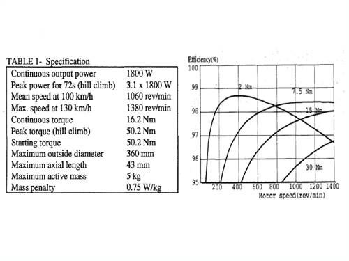
If you go to http://www.csiro.au/resources/pf11g.html#design and hit download you will get all the technical details of the motor and the configeration drawings. Attached is an image of the basic specs and efficiency curve. Jamie Better is the enemy of good |
||||
| MacGyver Guru Joined: 12/05/2009 Location: United StatesPosts: 1329 |
Drawings are dandy, but the proof is in the pudding, as they say. Build it and we'll all shower you with accolades. I'll hide and watch.  Nothing difficult is ever easy! Perhaps better stated in the words of Morgan Freeman, "Where there is no struggle, there is no progress!" Copeville, Texas |
||||
oztules Guru Joined: 26/07/2007 Location: AustraliaPosts: 1686 |
MacGyver. You are correct. There is no resistance at all to startup. Once cutin is achieved, the drag is proportional to drain. In the 3 phase style, there is no cogging feeling at start up or any other rpm into a linear load (R)... nil It is silky smooth. There will be a vibration in the tower from the magnetic impact of action/reaction on the coils from the wave fronts when charging batteries. This is due to the poor PF from driving a non-linear load. Others call this crest factor, as the lower (less than BattV) part of the wave form is not used, but you hammer the top.... making a square wave. The harmonics are numerous, but of little interest to us. It has no vibration at all on a resistive load or short circuit. For JB@Mirand. The figures are useless at this stage. I will check your site later, but it is the coil impedance/resistance I would be interested in. Your figures will drop like a rock using it as a generator driving a near zero impedance load. The axial flux is near 100% efficient at cut in, and will drop to 50% at maximum power. At this point and onwards it will continue to output, but burn up is likely. Mine will do 5kw all day into a R load, but less than 1.5- 2kw continuous into batteries@ design voltage, and 3-4kw into my 96v bank. An indication will be coil (EMF (DC)- battV)^2/starphase R. or phase R if using independant rectification or Delta. This will give you your stator losses. 98% is when your doing no real power into the batts. Missus is dragging me out to tea so I will try to view your site later. .............oztules Village idiot...or... just another hack out of his depth |
||||
| GWatPE Senior Member Joined: 01/09/2006 Location: AustraliaPosts: 2127 |
Hi Mac, These units have been made, no need to hide and watch. Hi Jamie, Here are some pics I posted a while ago here, on my own dual rotor AxFx alternator/motor that I built, and have made into a windmill alternator. Pic 1 is the alternator and Yaw box, with the alternator apart. Pic 2 is just the stator. I would not make another windmill this same way. The newer design, I proposed and built, and that Phill has also built is a much simpler coil and magnet arrangement. My unit is a closed design, but there are other similar open type designs. The overlapping coils and generous magnet volume offer certain benefits for high power density and light weight, and high efficiency. The high efficiency can be obtained at limited power levels in most AxFx alternators, low winding resistance is obviously the key. There are many other factors that affect ultimate windmill performance, and alternator efficiency comes some way down the list. It is however, possibly the easiest to measure. Better than 90% AxFx alternator efficiency should be obtained, even up to nom power output. It is relatively easy to compromize the alternator performance in the manufacturing though. A windmill wound for 100V operation and of 1000W output, with approx 1ohm coils. Reasonably easy to make. eficiency would be above 90% at the 1000W. At 500W, the efficiency would be above 95%. Higher efficiency is obtained with larger rotors, using more copper and more magnets at the same rpm, with the penalty of larger mass. The alternator from CSIRO quoted above, used in a normal windmill arrangement would operate at approx max 500 RPM. The graph shows that high efficiency only occurs at low torque[power/current] as well. The efficiency would be around 95% or less as a windmill at maximum power levels. The mass production of an interlocking winding should be possible. The 44 coils in my stator winding took 70 hours to wind, and many more to make the finished stator. I could not justify any more effort to even make a spare. I chose to revisit with a simpler design and allow others to make their own windmill alternator from a description. Phill has managed to get 3kW from his unit. I am sure others will make their own along similar lines. I am building my second. Wind coils for low resistance and high cutin RPM. Use voltage boost with Caps, or Electronic DC-DC booster. I am all for getting the most from the least. The cost of the ultimate, small scale windmill using an alternator of the overlapping coil design far exceeds the simpler coil arrangements. For a fraction of the cost, with similar ballpark efficiency you can make the non overlapping coil version. Gordon. become more energy aware |
||||
| JB@Marand Newbie Joined: 13/01/2010 Location: AustraliaPosts: 4 |
Hi Gordon, I like your work, very good. The CSIRO guys have spent a lot of time optimisim their design, your design is very similar. I agree the trick for me is in minimising the cost will be the speed at which I can complete the windings. Jamie Better is the enemy of good |
||||
| MacGyver Guru Joined: 12/05/2009 Location: United StatesPosts: 1329 |
Oz How do I decide how many magnets and how many coils? I am planning on using 24 coils (they're little) with three sets (phases) of 8 coils wired in series. The coils will likely be poured into polyester casting resin, cause the epoxy smell makes me puke! 
My magnet-holding ring, which will be drilled to hold the 1/4" neo-magnets (carefully press-fit into the thing) is approximately 7 inches in diameter. That's all my little lathe will swing, so that's as big as I can get it. The ring is made of HDPE (plastic) and I plan on putting a soft iron ring atop the magnets on the top ring and under the magnets on the lower ring to help route the magnetic flux lines. It's a dandy idea; wish I could take credit for it, but someone else here on the 4m came up with it; not me. The magnets will be set in approximately 3/8" from the exterior (around the circumference). There will be a top and a bottom ring of magnets spinning in unison with flux passing N-S-N-S through every other stacked pair (one magnet each side of the stationary coil) and the next stack will be S-N-S-N. I have no idea as to how many magnets to sink into this puppy. All I know is that I'd like to have one more pair of magnets than I have coils or maybe some other combination to help eliminate vibrations once the thing is generating current. I'm really pretty clueless with the electrical stuff. How am I doing so far? . . . . . Mac Nothing difficult is ever easy! Perhaps better stated in the words of Morgan Freeman, "Where there is no struggle, there is no progress!" Copeville, Texas |
||||
| Downwind Guru Joined: 09/09/2009 Location: AustraliaPosts: 2333 |
Mac, Are you sure you have your resins around the right way as epoxy has very little smell and polyester stinks to high heaven. Epoxy is much dearer cost wise than polyester. I would put a layer or two of glass in it if able as resin has little strength without it. Pete. Sometimes it just works |
||||
| MacGyver Guru Joined: 12/05/2009 Location: United StatesPosts: 1329 |
Pete Yeah, I know. The poly is a sweet smell (nauseatingly sweet), but the other stuff actually makes me gag. It's psychological probably. It's like when I was a kid and my mother (a stunt pilot) used to take me flying with her. I got sick every time, but it wasn't until my feet were planted on the ground that I'd do the deed. I had my own personal wheel chock that I'd target each time I climbed out of that stupid back seat! I was considering just machining some posts into a piece of acrylic with my mill (about a month's worth of tedious work unless I fashion some kind of fancy fly cutter!) and slapping some sheets on the sides, then using clear acrylic glue to seal things against Mother Nature. Maybe I'll look into a friend doing the epoxy gig for me. I'll look into it; thanks for the help. Nothing difficult is ever easy! Perhaps better stated in the words of Morgan Freeman, "Where there is no struggle, there is no progress!" Copeville, Texas |
||||
| Downwind Guru Joined: 09/09/2009 Location: AustraliaPosts: 2333 |
As for machining the acrylic, that sounds like a good job for a cnc router, set it and walk away. Is about time a clever bear like yourself built a cnc router and than these tedious jobs in soft material will be a pleasure. I would think you would still need to set the coils in some resin even if they are sealed in the acrylic. Or the coils will vibrate and damage them. Try a peg on your nose 
Remind me not to get the seat on the plane in front of you, and to exit after you! RrrrRolf...... Pete Sometimes it just works |
||||
| MacGyver Guru Joined: 12/05/2009 Location: United StatesPosts: 1329 |
[Quote=Downwind]It's about time a clever bear like yourself built a cnc router and then these tedious jobs in soft material will be a pleasure. I could kick myself. My neighbor THREW AWAY a CNC mill (Sherline) and the neighbor on the other side of the street saw it and fished it out of the bin. All that was "wrong" with it was some dust and dirt had stuck a few parts. A little oil and it was good as new! He said I could use it anytime I wanted, but still, I'm extremely jealous! As for the flying, I was 10 years old! I don't think I would even fit in the cockpit now; and if I could, it'd be too much temptation not to grab that joy stick or jam down the rudder pedals now and then just to keep mom on her toes! Actually, she gave up her license at age 65 after one last fling in a Stutz. I'll toy around with the coils this weekend and let everyone know what I decide. Thanks. Nothing difficult is ever easy! Perhaps better stated in the words of Morgan Freeman, "Where there is no struggle, there is no progress!" Copeville, Texas |
||||
| oztules Guru Joined: 26/07/2007 Location: AustraliaPosts: 1686 |
Best magnet space seems to be about 1/2 magnet width between magnets. Coil number should be 4:3... so 24 magnets needs 18 coils for three phase single layer coils. Coil inner diameter is about magnet size or a little less. Outer coil size... get them to virtually touch the next coil. Coil / stator thickness: try not to exceed 3/4 of twice the magnet thickness....for 1/2" mags that would be 3/4" gap between plate to plate magnets. so stator of less than 5/8" with 1/16th inch air gap on either side would give you the optimum output. Steel ring should be about 1/4" thick behind the magnets. Not sure your HDPE is up to the job of keeping the magnets apart. There may be too much flex. Just use 2 x 7" x 1/4" plate steel This will give you strength, simplicity, and something to mount your bearing housing on. Neo rots easily... so if you use a magnet holding material (plastic ect), make sure water cannot get between the sandwich and rust/corrode everything. .............oztules Village idiot...or... just another hack out of his depth |
||||
| GWatPE Senior Member Joined: 01/09/2006 Location: AustraliaPosts: 2127 |
Hi MacGyver, You are planning on 1/4" dia magnets??? I suppose these will be 1/4" to 1/2" long??? The coils that you plan on winding will have an ID of <1/4" and an OD of about 3/8"-1". Harnessing the flux will probably need many turns of thin wire, with a high resistance penalty. The very small magnet dia should require a narrow coil thickness and magnet separation, or the flux lines will just jump to the adjacent magnet. I used 3mm magnet separation on 25mm square magnets, and 18mm magnet separation on 50mm dia round magnets of 1/2" thiskness. Placing the magnets further apart on the plates will allow a wider plate separation with more space for wire. I am not sure of the usefullness of your design, but you should see relationships between magnet separation, coil turns etc on voltage and current at various rpm, into the loading. Gordon. become more energy aware |
||||
| Tinker Guru Joined: 07/11/2007 Location: AustraliaPosts: 1904 |
As Gordon writes above, using small neo magnets gives disappointing results. I played around with 12mm dia x 6mm thick magnets, making a triple rotor, dual stator AXFX alternator. Air gap was 7mm, results were very disappointing. Mk II model used 15mm diameter x 7mm thick magnets, still very disappointing results. But, it was very educational  . .Klaus |
||||
| MacGyver Guru Joined: 12/05/2009 Location: United StatesPosts: 1329 |
Crew: Well, that's about par. Still, I have about 100 of these little buggers, so I'm going to press on. All I want is to be able to charge my lawn-tractor 12-volt battery. It's not like I'm asking for the moon. Still, I see your point. I have a sleeping disorder and subsequently only require a few hours' sleep a night, so I spend a lot of time reading, staring at the ceiling and dreaming about ways to do stuff. You'll likely see posts from me at 2 in the morning sometimes. Last evening was no exception and I gave some thought to making just one giant coil winding all around the thing with the wire passing from outside to inside edge of the donut-shaped platform going all the way around and ending up where it starts. Edit I forgot to say that the pole lineup would change for this one-coil idea and I would make the top rotor have all down-facing poles N and the bottom rotor all up-facing poles that are S. This would give one giant flux going in one direction through one giant coil. Would this work or am I dreaming? Nothing difficult is ever easy! Perhaps better stated in the words of Morgan Freeman, "Where there is no struggle, there is no progress!" Copeville, Texas |
||||
| GWatPE Senior Member Joined: 01/09/2006 Location: AustraliaPosts: 2127 |
Hi MacGyver, "Alternator" should give away what we are trying to achieve. You would be better OFF making a jig to convert those tiny magnets into a bigger, more useful item. Mixing aluminium powder into epoxy, and gluing many same polarity orientation together should work. Not quite as good as a single magnet but still OK. Run this through the biological computer. Gordon. become more energy aware |
||||
| MacGyver Guru Joined: 12/05/2009 Location: United StatesPosts: 1329 |
Well, true to form, I'm about half-way through this project and think I have come up with "a better mousetrap" so to speak. Remember, I'm the one that doesn't sleep much and have a lot of "think" time on my hands. I'll finish what I've started, but I think I've come up with a way around using brushes to transmit electricity down to the ground from a HAWT without just dangling wires that have to be unwound off the tower every now and then. The new design is a perfect fit for the HAWT and lets face it, the HAWT is the industry standard for a good reason; it works better than any other design. I'll draw it up and post the picture here soon. I think by design, it will qualify as a radial-flux alternator. I'll likely start it in a new thread. Get ready to smile! I like that a VAWT dodges the need for yaw control, but at the same time like the fact that a HAWT takes advantage of apparent wind as well as uses all the wind of its swept area. Nothing like a little dilemma when you're between builds. I finished putting the blades on the VAWT this afternoon and will have the "test stand" finished by morning. We're in for a blow, so that'll be a good time to test the VAWT. Nothing difficult is ever easy! Perhaps better stated in the words of Morgan Freeman, "Where there is no struggle, there is no progress!" Copeville, Texas |
||||
| Dinges Senior Member Joined: 04/01/2008 Location: AlbaniaPosts: 510 |
[quote=MacGyver]and think I have come up with "a better mousetrap" so to speak.[/quote] A better one than KarlJ's cat?! Curious as to your solution.... only thing I can come up with is to let the generator light a lightbulb (which rotates along with the generator on its yaw pivot), which shines on a stationary PV panel.... Peter. (<-- wonders if that idea has been patented already....) |
||||
| HeadsUp Regular Member Joined: 06/12/2009 Location: AustraliaPosts: 43 |
small question can someone describe the difference in output between using round coils vs triangular shaped ones ? and why is it so ? i know the relationship of wire size and number of turns relates to voltage at "X" RPM but what about the coil shape vs magnets and also......... whatever shape coil you used , is it better to have a north and south magnet close enough together that they enter and leave a coil with optimised timing to boost the mag flux imposed on that particular coil ? if it means changing the shape and size of the coil in order to match the magnet timing , then could that be more important to incorporate into design structure ? you can always add more magnets or more coils to suit the circumference of the stator thoughts ? |
||||
