
|
|
Forum Index : Other Stuff : New F&P micro hydro generator
| Page 1 of 3 |
|||||
| Author | Message | ||||
SSW_squall Senior Member Joined: 20/03/2010 Location: AustraliaPosts: 111 |
This is going to be an on going thread, as i document the fabrication and constuction of my new micro-hydro generator which will from the basis of my RE system. I'll put up some photos & notes about the old proof-of-concept system to show what's already been made/done Any comments (well, any non-w&#ker comments) will be welcome... SO EXCITED 
The new parts arrived this afternoon from ecoinovation, from (insert kiwi accent) Nu Zulaind... 
1x Pelton rotor 1x Shaft + bearing holder + slinger seal 6x 50mm conical jets + holder Hats off to Micheal Lawley, who has to be regarded as THE expert on these F&P hydro units. The parts are VERY NICELY made, will post some photo in due course. I've got a 60S smart drive stator thats yet to be rewired. Given my system is 48V i'm thinking that 7x2 configuration, in either star or delta would be the way to go. Any thoughts on this?? As for the rain, meaning water to run the hydro system. We (in Adelaide) have had some outstanding falls in the last couple of days, to get the ball rolling for winter. Yesterday morning between 6 and 8 AM we had over 50mm!! Almost jumped out of bed onto the floor, with the thunder. It was pouring cats and dogs!! The dam which is about 10m x 7m filled up 0.75m so as of this morning it's full!! AB Einstein: Everything should be made as simple as possible, but not one bit simpler |
||||
| davef Guru Joined: 14/05/2006 Location: New ZealandPosts: 499 |
What is the head and expected flowrate from your dam? |
||||
| kingull Regular Member Joined: 08/04/2010 Location: AustraliaPosts: 44 |
That Eco Innovation should pay you commission. There site is pretty good but you cant contact them unless you register with them. Their high voltage unit is my pick as the distance from generator to house is 130 metres. Their data sheets appear to show correct flow rates where others in Australia seem to be way out. |
||||
| SSW_squall Senior Member Joined: 20/03/2010 Location: AustraliaPosts: 111 |
First some photos of the parts: The pelton rotor: 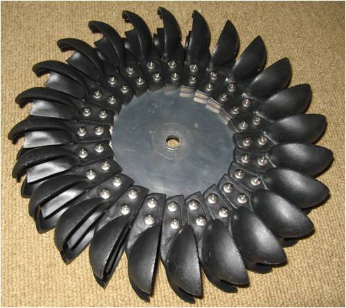
With a close up of the spoons: 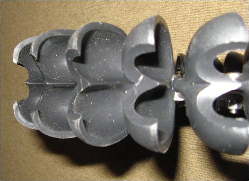
The shaft and bearing block assembly: 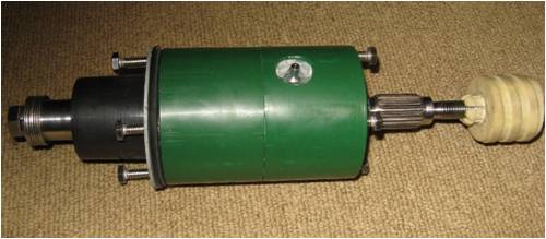
A close up of the water "slinger" seal: 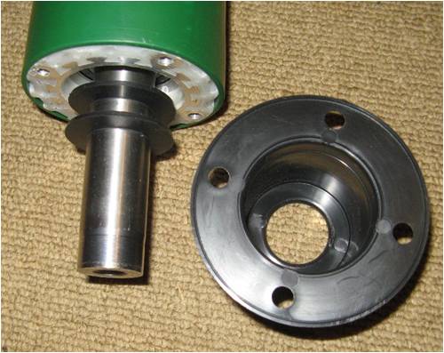
The jet block and conical jets. The jet nozzle can be cut to allow different holes sizes for less/more flow: 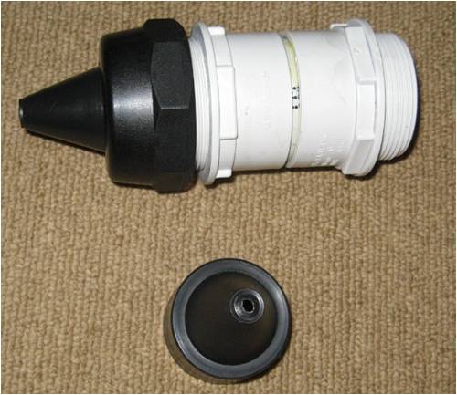
Einstein: Everything should be made as simple as possible, but not one bit simpler |
||||
| SSW_squall Senior Member Joined: 20/03/2010 Location: AustraliaPosts: 111 |
Cause i design stuff for my job, i'm always on the look-out for really good design that: cost effective, robust, simple ect If you look at alot of everyday products out, it's amazing there are so many where the design has not been totaly thought through or optimised. So you have got to give credit where it's due... I did email Micheal, with a few questions before i ordered the stuff and he was quite helpful... He does have a bussiness to run, so you can understand why he has to limit the amount of phone calls and emails. I know cause we get enough DIY nutcases ringing up at work wanting to know if they buy drivers and advise on how to design a crossover and what port diameter/length to use and what volume enclosure and will X brand speaker cable sound better then Y brand speaker cable and so it goes on... Of course that why we have this forum's, so we can share good ideas and information a non-professional context, which is more fun anyway. Back to the hydro: The penstock is approx 160m of 90mm storm water pipe, the static head is 13m and the flow can be anywhere from 1L/s upwards to 5L/s or more if the creeks really flowing hard. AB Einstein: Everything should be made as simple as possible, but not one bit simpler |
||||
Downwind Guru Joined: 09/09/2009 Location: AustraliaPosts: 2333 |
I like the look of the kit. Are you going to tell us the cost of the kit? Pete. Sometimes it just works |
||||
| GWatPE Senior Member Joined: 01/09/2006 Location: AustraliaPosts: 2127 |
Hi AB, does the dam have a continuous feed, and approx what is the feed volume rate? What is the expected water head available? How far from the water course to the battery? What is the expected power loading that the micro hydro, as the basis of your RE will be expected to produce? What rpm do you expect the alternator will spin at, given your system voltage is 48V? This will determine the power that can be produced from a rewire. Micro hydro is a great option in the right location. I hope you can fill in some blanks, and you don't mind me asking the questions. Gordon. PS edit. I see some activity while I was typing. How many months does the water flow? become more energy aware |
||||
| SSW_squall Senior Member Joined: 20/03/2010 Location: AustraliaPosts: 111 |
Hi pete, Its not really a kit per-say, the ecoinnovation website has all the parts listed separately Here So i just ordered what i needed and payed the prices listed which was about 400AUD including postage (the NZ exchange rate is good at the moment). I didn't need to order a F&P smart drive cause i've got one that i obtained from an old washing machine a while ago... Given it should generate at least 2kWh a day depending on how the creek is flowing, it's not too bad for the money... AB Einstein: Everything should be made as simple as possible, but not one bit simpler |
||||
| SSW_squall Senior Member Joined: 20/03/2010 Location: AustraliaPosts: 111 |
Nah i don't mind at all Gordon Here's afew more photo's of the old proof-of-concept hydro system (should help answer some of your Q's): The first time turned the on the tap, i was just amazed at the power of the water just blasting out of the nozzle. The penstock contains almost 1000L of water and just by tapping the pipe you can tell it's holding back a nice little wall of water: 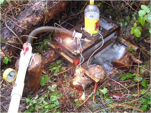
Heres the water intake, with typical flow: 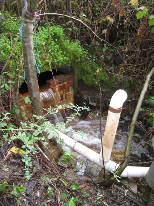
The underside of the "turgo" turbine (frame now painted) 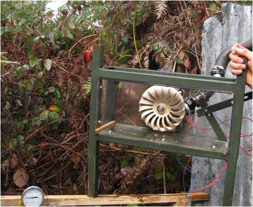
I extended the penstock down the creek to gain an extra 1.5m of fall, from the first test location. 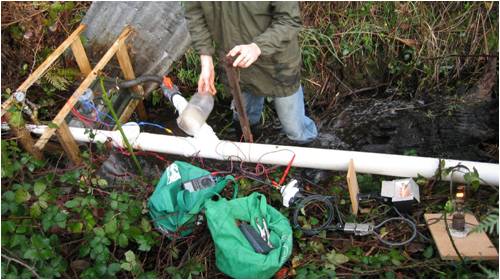
The meter shows 43.7v and the power output is about 100W The big light bulb is a 1000w projector lamp. The creek is quite seasonal, it has just started flowing this month with the rain we have just had and it stops flowing in about November. Generally For at least 3-4 Months of the year there is useable flow AB Einstein: Everything should be made as simple as possible, but not one bit simpler |
||||
| Downwind Guru Joined: 09/09/2009 Location: AustraliaPosts: 2333 |
Hi, Is the 13m you quote TVD (true vertical depth) if so you will have 18.5psi over the 42 foot TVD. The flow rate of the creek will have little bearing on the turbine flow as long as it is in excess of the turbines requirements. Hence changing your nozzle size for different seasons will increase or decrease the power capacity greatly. Pete. Sometimes it just works |
||||
| SSW_squall Senior Member Joined: 20/03/2010 Location: AustraliaPosts: 111 |
Pete, You are correct regarding the vertical drop: I get about 18PSI or 125kPa of pressure Exactly right on the nozzles too. That the static head, mind you When the water starts flowing there is DYNAMIC HEAD LOSS, caused by the friction of the water with the inside of the penstock (pipe). At flow rates of 2-3L/s this is about 0.4m Because the dynamic head loss is a 4th power relationship with the diameter of the pipe, the effect is much more significant than you'd think at a glance. If the pipe was only half the diameter (say 40mm) the head loss would be in the order of several meters for the same flow, this would severly reduce the power output of the system. Actually i want to extend the penstock about another 30m down the creek to get 15m total fall(head) but that will involve hacking through a 2m high wall of very prickely blackberry bushes On the first hydro rig i've used a 38mm radiator hose feeding into a 1 inch threaded pipe joiner, into which the 19mm irrigation barb nozzle was screwed. I'm fairly sure this was choking off the pressure right at the jet, as changing to a larger nozzle didn't really gain me that much more power output even if abit more water was flowing. Hence the new ecoinovation jets have a 50mm pipe fitting and will be connected with some flexible 50mm drafting hose, hopefully delivering some reasonable improvements. To answer some more of Gordons Q's: |
||||
| Downwind Guru Joined: 09/09/2009 Location: AustraliaPosts: 2333 |
To calculate the head pressure in PSI its...8.34 X 0.052 X TVD in feet. So 15m = 49 foot. 8.34 x 0.052 x 49 = 21.3 PSI. Elbows and bends cause huge friction losses and it looks like you have used 75mm storm water pipe? 90mm would be better and funny enough its cheaper than 75mm. You might want to consider replacing the first few sections with 90mm. The conical jets will give a great improvement over the directors (barb fittings) you used in your trial as the directors worked as a restrictor more than a jet. Pete. Sometimes it just works |
||||
| GWatPE Senior Member Joined: 01/09/2006 Location: AustraliaPosts: 2127 |
As you have a dam at the top, and you will have a battery, I would design the jet system for around 70% of the maximum flow, and use a flow gate arangement to allow the dam to fill, and drain, in low flow conditions. The flow ranges from 5L/s down to zero, so in the wet months, the system could stay ON. The only control, would be a few float switches, that would toggle the valving. As the flow decreased, the dam would fill less frequently, before the valve was opened. This system will require only one optimum jet, and the wheel will start as soon as the water was turned ON. The dam will provide approx 8 hours capacity at 1L/s, so approx 3L/s in feed will give 24 hour operation. Hydro systems are difficult to optimize for varying flows, so using a header dam and gating the flow for stop-start operation keeps the hydraulic system at an optimum. The pressures are low, so large bore, low loss, irrigation solenoids will be OK to gate the flow at the bottom, just before the jet. The same hydraulic controls can be used for the electrical system regulation, when the battery is fully charged. Gordon. become more energy aware |
||||
| SSW_squall Senior Member Joined: 20/03/2010 Location: AustraliaPosts: 111 |
49 feet?? To quote Grampa (abe) simpson: "The metric system is the tool of the devil. My car gets fourty rods to the hogs head and that's the way I likes it" hehe
Even though i'm one of the young generation, i've learnt to think in both systems of units. Especially because in the world of PCB design most of the components are drawn and spaced in mils or thousandths of inch. 20 pounds would be great, cause it means that the same amount of water can do that much more work. Actually the pipe is 90mm, except where it narrows down toward the 50mm ball valves at the end. Absolutely right on the cost, 90mm is cheaper than 75mm, i think it has to do with fact that 90mm is more commonly used. AB Einstein: Everything should be made as simple as possible, but not one bit simpler |
||||
| Downwind Guru Joined: 09/09/2009 Location: AustraliaPosts: 2333 |
I dont think irrigation solenoids would be the way to go due to the internal losses and the pressure required to open them. A valve with a actuator on it would be far better with low pressure systems. Pete. Sometimes it just works |
||||
| kingull Regular Member Joined: 08/04/2010 Location: AustraliaPosts: 44 |
Like running into a brick wall(solenoids) |
||||
| SSW_squall Senior Member Joined: 20/03/2010 Location: AustraliaPosts: 111 |
Good suggestion Gordon: Actually the penstock actually bypasses our main water storage dam, which is below the water intake weir seen in the photo. I did it this way for a couple of reasons: 1. It gains an extra 2m of fall 2. Without raising the height of the dam, the outlet of the dam doesn't really lend it's self to becoming the water inlet weir. 3. It was easy to brick up to concrete culvert in the photo and brick the pipe into it Having said that the intake weir does store some water, maybe a 3000-4000L So I have had some similar ideas, perhaps a float switch that can actuate a ball valve with a windscreen wiper motor to turn on the second jet, if the flow is availiable... Turning on and off valves on the penstock has to be done SLOWLY, as there is approx 1 ton of water on the move!! If that comes to a halt suddenly the pipe would be shattered by the water hammer, releasing a mini tsunami. As it stands closing the valve over a 5 seconds the pressure gauage see-saws up and down, even with a small bleed valve open to help release some of the pressure spikes The stand pipe just below the intake weir is to stop the pipe from collapsing in on it's self due to the suction if something were to inadvertantly block the intake?! Or if i block it off deliberately to empty to penstock... AB Einstein: Everything should be made as simple as possible, but not one bit simpler |
||||
| SSW_squall Senior Member Joined: 20/03/2010 Location: AustraliaPosts: 111 |
A quick update: Decided not to stuff around trying to weld up the chassis for the turbine myself, i'm getting it made out of statinless steel... We have an expert metal fabricator, Nick Besa, who's round the corner from work. He does alot of of the cinema horn stack brakets and other odd jobs (like making a bomb proof 2m square metal server room) Anyway he was round at work last week complaining that work had been really quiet and had nothing to do. Mainly because the poor guy got diagnosed with bowel cancer last year and had to have half his guts chopped out, chemotherapy, radiotherapy the whole works. Of course he's had alot of time away from work, hence poeple have been taking their jobs elsewhere. So i though i'd give him the task of making up the box for my pelton turbine: He happened to had some 800mm square metal signs made from 2mm food grade stainless steel, that were ordered but then not collected/wanted. So he's folding up the box out of one of these panels, heres pic taken this morning before it's been folded: 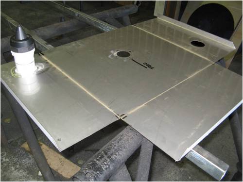
I think he enjoying the slightly off-beat project, which great cause so far it is looking spot on. I'm so glad i didn't bother trying to stuff around myself Will post more pic's as it comes togther... AB Einstein: Everything should be made as simple as possible, but not one bit simpler |
||||
| SSW_squall Senior Member Joined: 20/03/2010 Location: AustraliaPosts: 111 |
Here's a pic of the box after it's been folded and welded: 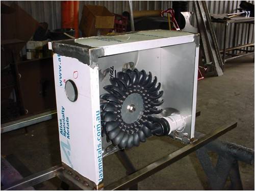
The bracing and mounting bars that run along the bottom are 25mm stainless tube 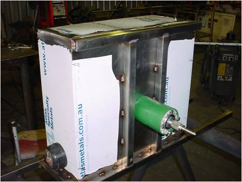
The box ended up being a little bigger than i'd planned but that's fine because it will give the spray plenty of space to fall away without interfering with the rotation of the pelton runner. The front, which is currently open, will be sealed off with a piece of clear polycarbonate sheeting, so i can see what going on when the machine is running. All thats left is to apply the pickling paste to the welds to remove the burn marks, pull off the plastic covering and it should be all finished!!! AB Einstein: Everything should be made as simple as possible, but not one bit simpler |
||||
| Downwind Guru Joined: 09/09/2009 Location: AustraliaPosts: 2333 |
Hi AB, It be worth getting him to make an enclosure for the F&P as well. From what i understand they dont handle the moist conditions all that well. A nice box or drop over cover off the back with the F&P in it would be an advantage for the longer term. Nice work by Nick. Pete. Sometimes it just works |
||||
| Page 1 of 3 |
|||||
| The Back Shed's forum code is written, and hosted, in Australia. | © JAQ Software 2026 |
