
|
|
Forum Index : Other Stuff : 2 projects of interest on the go
| Page 1 of 3 |
|||||
| Author | Message | ||||
| Gizmo Admin Group Joined: 05/06/2004 Location: AustraliaPosts: 5186 |
I have a couple of projects that might be of interest. Well I know one will definitely be of interest, save that till last. First up, I have one of Phills windmills to test out at a fiends ( Bill ) place. Its a 24v model, and we want to see how it performs. The location has never had a wind turbine or solar before, so I needed a windmill controller and some way for Bill to record the power output from time to time. I was going to use a TL084 controller and a couple of multimeter's so Bill could take some readings, but then I remembered I have the Picaxe Charge Controller. It can display volts and amps on its little screen, and work as a controller too. I'm going to rewrite its software to display current watts and watt peak. This means the software will loose the low battery alarm sub routine, and the on screen text will be abbreviated, there just isn't enough memory to keep these features and add watts displays. The controller will display the watt peak until the controller is reset ( turned off and on ), meaning Bill can go out to the controller once a day and record the peak power from the wind turbine. The other project on the go is something a lot of people have been asking for, I only hope I can make it happen. An axial flux project. The axial flux windmills built by Gordon and Phill are very good performers, and improve in many ways on the Other Power/ Hugh designs. But they are a very high precision device, and difficult to make without the right tools ( big lathe ). So I wanted to put together a design that can be made without a lathe. The new design needs no special tools, just like the Other Power / Hugh design, should be easier to make, and uses less epoxy. The smaller stronger stator should also be more reliable. Will keep you posted. Glenn The best time to plant a tree was twenty years ago, the second best time is right now. JAQ |
||||
| vasi Guru Joined: 23/03/2007 Location: RomaniaPosts: 1697 |
[quote]...should be easier to make, and uses less epoxy.[/quote] Just WOW! I can't wait! Hobbit name: Togo Toadfoot of Frogmorton Elvish name: Mablung Miriel Beyound Arduino Lang |
||||
| Gizmo Admin Group Joined: 05/06/2004 Location: AustraliaPosts: 5186 |
Thanks Vasi, its good to know someone reads my posts 
Discovered today the old 28X chips dont work with the Dick Smith USB to Serial converters. My laptop doesn't have a serial port, so I have to use the adapter to program PicAxe chips. No go with the 28X, it locks up the editor solid, have to use taskmanager to kill the process. I tried my desk PC, with its real serial port, and no problems, works perfectly. I dont know if you can buy a laptop with a serial port, or even a parallel port, these days. Its a real shame. The serial to USB adapters are rubbish from what I've heard. Glenn The best time to plant a tree was twenty years ago, the second best time is right now. JAQ |
||||
| sPuDd Senior Member Joined: 10/07/2007 Location: AustraliaPosts: 251 |
Gizmo, Dontronics has the best adaptor money can buy. Its the only one certified by all out security panel companies to work with their software and hardware: Dontronics USB-Serial Adaptor Have used it on everything from 25 year old Honeywell PLC's to grade 1 high security panels and PICAXE chips. Well worth the ca$h 
sPuDd.. It should work ...in theory |
||||
| VK4AYQ Guru Joined: 02/12/2009 Location: AustraliaPosts: 2539 |
Hi Gizmo Like the sound of your new alternator, ca it work at low rpm 120 for a VAWT All the best Bob Foolin Around |
||||
| vasi Guru Joined: 23/03/2007 Location: RomaniaPosts: 1697 |
Hi Glenn, Please, see your PM
Vasi Hobbit name: Togo Toadfoot of Frogmorton Elvish name: Mablung Miriel Beyound Arduino Lang |
||||
| Gizmo Admin Group Joined: 05/06/2004 Location: AustraliaPosts: 5186 |
OK, this is the new code for the charge controller. Its now a dump controller, and I've used both mosfet outputs together to drive two dumploads. The dump loads switch .5 of a second apart to smooth out the sudden drop in battery voltage a little. The screen displays volts, amps, watts and watt peak. Most internal maths is now done using words instead of bytes. I've use the eeprom as a temporary storage of data, meaning I can reuse the word variables for calculations. Using words means I have increased the usable volts and range of the charger, at least in the software. It should now work on a 12, 24, 36 and 48 volt system, but the internal regulator would need to be changed once you go over 30v. Amps is +- 50 with a resolution of 0.1A, instead of +- 12.5 with a resolution of 0.1A. The watts calculations were a nightmare. Sine we are stuck with integer maths, as an example 26.5v and 30.1 amps is actually 265 and 301 in the software. Watts would be 265*301=79765. That number is too big for a picaxe, its max is 65536. To solve this I divided currents over 20 by 10 and moved the decimal place, reduced resolution but better maths. ] 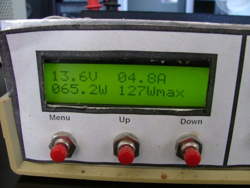
The watt peak is reset by turning the charger off and on. I've also added a amp offset zero function to the setup menu. This will zero the amp reading. The codes below, I'll add it to the web site once its proven itself, there may still be bugs in it. Glenn ' Charge Controller ' Ver 2010A ' www.thebackshed.com Start: EEPROM 0,( $33 ) EEPROM 1,( $32 ) EEPROM 2,( $28 ) EEPROM 3,( $0C ) EEPROM 4,( $06 ) EEPROM 5,( $01 ) EEPROM 6,("V ") EEPROM 9,("A ") EEPROM 12,("W ") EEPROM 15,("Wmax ") EEPROM 22,("Set Load On V") EEPROM 35,("Set Load Off V") EEPROM 50,("Zero Amp Offset") EEPROM 66,("Press UP") EEPROM 75,("Done ") W0=0 ' Set min watt max write 110, WORD W0 ' Check to see if we have any dum load switching values read 112, WORD W0 if W0=0 then ' if no saved load switch levels, set some defaults W0=120 write 112, WORD W0 W0=140 write 114, WORD W0 end if ' Check the current offset value. read 116, WORD W0 if W0=0 then W0=500 write 116, WORD W0 end if ' Initialise the LCD display FOR b11 = 0 TO 5 READ b11,b12 pause 15 GOSUB SendCmdByte NEXT ' start up been and turn off dump load gosub Beep low portc 5 low portc 4 goto main Main: nap 4 ' Have a little sleep to save some power. readadc10 0,W0 'Read in the volts and amps write 100,WORD W0 readadc10 1,W0 write 102,WORD W0 gosub DisplayVolt gosub DisplayAmp gosub DisplayWatt if pin1 = 1 then menu1 ' Is menu button pressed? if pin6 = 0 then OnLoad ' Is Forced Load switch on? if pin7 = 0 then OnCharge ' Is Forced Charge switch on? read 100, WORD W0 read 114, WORD W1 if W0>W1 then SwitchToLoad 'Battery fully charged, switch windmill to Load. read 112, WORD W1 if W0<W1 then SwitchToCharging 'Battery gettin low, switch windmill to Battery. goto main SendCmdByte: b13 = %00000000 ; Send to Command register SendDataByte: pins = b12 & %11110000 | b13 ; Put MSB out first PULSOUT 3,1 ; Give a 10uS pulse on E pins = b12 * %00010000 | b13 ; Put LSB out second PULSOUT 3,1 ; Give a 10uS pulse on E b13 = %00000100 ; Send to Data register next RETURN SwitchToLoad: High portc 4 nap 5 High portc 5 ' Turn on MOSFETS to dummy load goto Main SwitchToCharging: low portc 5 nap 5 ' Turn off MOSFETS to dummy load low portc 4 goto Main DisplayVolt: b12 = 2 GOSUB SendCmdByte Read 100,WORD W0 W1=W0/100 b12=W1+48 GOSUB SendDataByte W1=W1*100 W0=W0-W1 W1=W0/10 b12=W1+48 GOSUB SendDataByte b12 = 46 Gosub SendDataByte W1=W1*10 W0=W0-W1 W1=W0 b12=W1+48 GOSUB SendDataByte FOR b11 = 6 TO 8 ' Display "V" READ b11,b12 GOSUB SendDataByte NEXT Return DisplayAmp: ' Same as above, but adds the - and + symbols for current Read 102,WORD W0 ' Get Amp Reading Read 116,WORD W3 ' Get Amp Offset If W0>W3 then pamp if W0<W3 then namp if W0=W3 then oamp goto d1 pamp: W0=W0-500 goto d1 namp: b12=45 GOSUB SendDataByte W0=W3-W0 goto d1 oamp: W0=0 goto d1 d1: W1=W0/100 b12=W1+48 GOSUB SendDataByte W1=W1*100 W0=W0-W1 W1=W0/10 b12=W1+48 GOSUB SendDataByte b12 = 46 Gosub SendDataByte W1=W1*10 W0=W0-W1 W1=W0 b12=W1+48 GOSUB SendDataByte FOR b11 = 9 TO 11 ' Display "A" READ b11,b12 GOSUB SendDataByte NEXT Return DisplayWatt: b12 = 192 GOSUB SendCmdByte ' move to 2nd line Read 100,WORD W0 ' Get Volts Read 102,WORD W1 ' Get Amps Read 116,WORD W3 ' Get Amps Offset W1=W1-W3 ' Subtract the offset, and then we no longer need W3 W3=W1/10 ' Work out watts for peak watt W3=W3*W0 W3=W3*10/82 ' yucky maths but works. We lost precision so need to fudge the figures Write 106, WORD W3' Save peaks watts if W1>200 then W1=W1/10 W3=W0*W1 W0=W3 W1=W0/10000 b12=W1+48 GOSUB SendDataByte W1=W1*10000 W0=W0-W1 W1=W0/1000 b12=W1+48 GOSUB SendDataByte W1=W1*1000 W0=W0-W1 W1=W0/100 b12=W1+48 GOSUB SendDataByte W1=W1*100 W0=W0-W1 W1=W0/10 b12=W1+48 GOSUB SendDataByte b12 = 46 Gosub SendDataByte W1=W1*10 W0=W0-W1 W1=W0 b12=W1+48 GOSUB SendDataByte else W3=W0*W1 W0=W3 W1=W0/10000 b12=W1+48 GOSUB SendDataByte W1=W1*10000 W0=W0-W1 W1=W0/1000 b12=W1+48 GOSUB SendDataByte W1=W1*1000 W0=W0-W1 W1=W0/100 b12=W1+48 GOSUB SendDataByte b12 = 46 Gosub SendDataByte W1=W1*100 W0=W0-W1 W1=W0/10 b12=W1+48 GOSUB SendDataByte end if FOR b11 = 12 TO 13 ' Display "W" READ b11,b12 GOSUB SendDataByte NEXT read 110, WORD W0 read 106, WORD W1 if W1>W0 then write 110, WORD W1 W0=W1 end if W1=W0/100 b12=W1+48 GOSUB SendDataByte W1=W1*100 W0=W0-W1 W1=W0/10 b12=W1+48 GOSUB SendDataByte W1=W1*10 W0=W0-W1 W1=W0 b12=W1+48 GOSUB SendDataByte FOR b11 = 15 TO 21 ' Display "Wpeak" READ b11,b12 GOSUB SendDataByte NEXT Return Menu1: 'Set the Charge Voltage "CVolt" GOSUB Beep pause 500 b12 = 1 GOSUB SendCmdByte b12 = 128 GOSUB SendCmdByte FOR b11 = 35 TO 48 'Display "Set Charge Volts" READ b11,b12 GOSUB SendDataByte NEXT read 112, WORD W0 write 100, WORD W0 gosub DisplayVoltLine2 Menu1a: pause 100 if pin1 = 1 then Menu2 if pin2 = 1 then UpChargeVolt if pin3 = 1 then DownChargeVolt goto Menu1a UpChargeVolt: W0 = W0 + 1 gosub DisplayVoltLine2 write 112,WORD W0 'save in eeprom goto Menu1a DownChargeVolt: W0 = W0 - 1 gosub DisplayVoltLine2 write 112,WORD W0 'save in eeprom goto Menu1a Menu2: 'Set the Load Voltage "LVolt" GOSUB Beep pause 500 b12 = 1 GOSUB SendCmdByte b12 = 128 GOSUB SendCmdByte FOR b11 = 22 TO 34 'Display "Set Load Volts" READ b11,b12 GOSUB SendDataByte NEXT read 114, WORD W0 gosub DisplayVoltLine2 Menu2a: pause 100 if pin1 = 1 then Menu3 if pin2 = 1 then UpLoadVolt if pin3 = 1 then DownLoadVolt goto Menu2a UpLoadVolt: W0 = W0 + 1 gosub DisplayVoltLine2 write 114,WORD W0 'save in eeprom goto Menu2a DownLoadVolt: W0 = W0 - 1 gosub DisplayVoltLine2 write 114,WORD W0 'save in eeprom goto Menu2a Menu3: 'Set the Load Voltage "LVolt" GOSUB Beep pause 500 b12 = 1 GOSUB SendCmdByte b12 = 128 GOSUB SendCmdByte FOR b11 = 50 TO 64 'Display "Zero amps offset" READ b11,b12 GOSUB SendDataByte NEXT b12 = 192 GOSUB SendCmdByte FOR b11 = 66 TO 73 'Display "Press UP" READ b11,b12 GOSUB SendDataByte NEXT Menu3a: pause 100 if pin1 = 1 then Start if pin2 = 1 then ZeroAmp goto Menu3a ZeroAmp: readadc10 1,W0 write 116,WORD W0 b12 = 192 GOSUB SendCmdByte ' move to 2nd line FOR b11 = 75 TO 82 'Display "Done " READ b11,b12 GOSUB SendDataByte NEXT gosub beep goto Menu3a OnLoad: gosub beep ' keep beeping to remind us the charger is in a manual state High portc 4 nap 5 High portc 5 Goto Main OnCharge: gosub beep ' keep beeping to remind us the charger is in a manual state low portc 5 nap 5 low portc 4 goto Main Beep: 'Make a noise. this pin cant use any tone commands so we need to write our own for b8=0 to 5 high portc 0 pause 1 low portc 0 pause 1 next return DisplayVoltLine2: b12 = 192 GOSUB SendCmdByte W3=W0 W1=W3/100 b12=W1+48 GOSUB SendDataByte W1=W1*100 W3=W3-W1 W1=W3/10 b12=W1+48 GOSUB SendDataByte b12 = 46 Gosub SendDataByte W1=W1*10 W3=W3-W1 W1=W3 b12=W1+48 GOSUB SendDataByte FOR b11 = 6 TO 8 ' Display "V" READ b11,b12 GOSUB SendDataByte NEXT Return The best time to plant a tree was twenty years ago, the second best time is right now. JAQ |
||||
Downwind Guru Joined: 09/09/2009 Location: AustraliaPosts: 2333 |
Hi Glenn, Nice work, but what ever happened to using symbols?..Your code dose my head in trying to read it and stay the variables and values 
Perhaps you could add a line prior to start with the picaxe use so we know what chip it is, like.....#picaxe 08m........I try to do it as a matter of course nowdays and it also configurers prog. editor for the chip. Its handy if you are swapping between 2 different chips with program changes. Why the dump delay and not a second adc value for the 2 stages? Pete. Sometimes it just works |
||||
| Gizmo Admin Group Joined: 05/06/2004 Location: AustraliaPosts: 5186 |
Hi Pete Didn't use symbols because the variables are used for different things. eg, one second W0 is used to store amps, next its used to calculate a voltage value in the display routine. I'm using the eeprom as storage instead of variables. That way I can free up the word variables to do the maths. A 2nd dump value could be added but I didnt need it for this application. Maybe later. The code above ( apart from the facts its got a negative watts bug ) is just for show and tell, I'll add some coments and format it better later. Glenn The best time to plant a tree was twenty years ago, the second best time is right now. JAQ |
||||
| Gizmo Admin Group Joined: 05/06/2004 Location: AustraliaPosts: 5186 |
OK Pete, couldn't help myself. This one lets you independantly set the cut in and out voltages for the two dump loads. Also a few other fixes. So the charger now displays volts, amps, watts and peak watts. You can set each dump load ( or whatever else you want to connect to the output, like a fan or waterpump ) to cut in and out at whatever voltage you set up in the menu. You might set a water pump to cut in once the batteries are fully charged, and a dump load to cut in if the batteries are starting to overcharge. Not much room left in the chip, using 1662 of 2048 bytes. ' Charge Controller ' Ver 2010A ' www.thebackshed.com Start: EEPROM 0,( $33 ) EEPROM 1,( $32 ) EEPROM 2,( $28 ) EEPROM 3,( $0C ) EEPROM 4,( $06 ) EEPROM 5,( $01 ) EEPROM 6,("V ") EEPROM 9,("A ") EEPROM 12,("W ") EEPROM 15,("Wmax ") EEPROM 22,("O/P 1 On ") EEPROM 31,("O/P 1 Off ") EEPROM 41,("O/P 2 On ") EEPROM 50,("O/P 2 Off ") EEPROM 60,("Zero Amp Offset") EEPROM 75,("Press UP ") EEPROM 84,("Done ") EEPROM 93,("Wait ") W0=0 ' Set min watt max write 110, WORD W0 ' Check to see if we have any dum load switching values read 112, WORD W0 if W0=0 then ' if no saved load switch levels, set some defaults W0=120 write 112, WORD W0 write 118, WORD W0 W0=140 write 114, WORD W0 write 120, WORD W0 end if ' Check the current offset value. read 116, WORD W0 if W0=0 then W0=500 write 116, WORD W0 end if ' Initialise the LCD display FOR b11 = 0 TO 5 READ b11,b12 pause 15 GOSUB SendCmdByte NEXT FOR b11 = 93 TO 97 ' Display "Wait" READ b11,b12 GOSUB SendDataByte NEXT ' start up been and turn off outputs gosub Beep low portc 5 low portc 4 nap 7 goto main Main: nap 4 ' Have a little sleep to save some power. readadc10 0,W0 'Read in the volts and amps write 100,WORD W0 readadc10 1,W0 write 102,WORD W0 gosub DisplayVolt gosub DisplayAmp gosub DisplayWatt if pin1 = 1 then menu1 ' Is menu button pressed? if pin6 = 0 then OnLoad ' Is Forced Load switch on? if pin7 = 0 then OnCharge ' Is Forced Charge switch on? read 100, WORD W0 read 114, WORD W1 if W0>W1 then 'Switch on O/P 1. High portc 4 end if read 112, WORD W1 if W0<W1 then 'Switch off O/P 1. Low portc 4 end if read 120, WORD W1 if W0>W1 then 'Switch on O/P 2. High portc 5 end if read 118, WORD W1 if W0<W1 then 'Switch off O/P 2. Low portc 5 end if goto main SendCmdByte: b13 = %00000000 ; Send to Command register SendDataByte: pins = b12 & %11110000 | b13 ; Put MSB out first PULSOUT 3,1 ; Give a 10uS pulse on E pins = b12 * %00010000 | b13 ; Put LSB out second PULSOUT 3,1 ; Give a 10uS pulse on E b13 = %00000100 ; Send to Data register next RETURN DisplayVolt: b12 = 2 GOSUB SendCmdByte Read 100,WORD W0 W1=W0/100 b12=W1+48 GOSUB SendDataByte W1=W1*100 W0=W0-W1 W1=W0/10 b12=W1+48 GOSUB SendDataByte b12 = 46 Gosub SendDataByte W1=W1*10 W0=W0-W1 W1=W0 b12=W1+48 GOSUB SendDataByte FOR b11 = 6 TO 8 ' Display "V" READ b11,b12 GOSUB SendDataByte NEXT Return DisplayAmp: ' Same as above, but adds the - and + symbols for current Read 102,WORD W0 ' Get Amp Reading Read 116,WORD W3 ' Get Amp Offset If W0>W3 then pamp if W0<W3 then namp if W0=W3 then oamp goto d1 pamp: W0=W0-W3 goto d1 namp: b12=45 GOSUB SendDataByte W0=W3-W0 goto d1 oamp: W0=0 goto d1 d1: W1=W0/100 b12=W1+48 GOSUB SendDataByte W1=W1*100 W0=W0-W1 W1=W0/10 b12=W1+48 GOSUB SendDataByte b12 = 46 Gosub SendDataByte W1=W1*10 W0=W0-W1 W1=W0 b12=W1+48 GOSUB SendDataByte FOR b11 = 9 TO 11 ' Display "A" READ b11,b12 GOSUB SendDataByte NEXT Return DisplayWatt: Read 102,WORD W1 ' Get Amps Read 116,WORD W3 ' Get Amps Offset if W1<W3 then W1=W3 end if Read 100,WORD W0 ' Get Volts b12 = 192 GOSUB SendCmdByte ' move to 2nd line W1=W1-W3 ' Subtract the offset, and then we no longer need W3 W3=W0/10 ' Work out watts for peak watt W3=W3*W1 W3=W3*10/97 ' yucky maths but works. We lost precision so need to fudge the figures Write 106, WORD W3' Save for peaks watts test if W1>200 then W1=W1/10 W3=W0*W1 W0=W3 W1=W0/10000 b12=W1+48 GOSUB SendDataByte W1=W1*10000 W0=W0-W1 W1=W0/1000 b12=W1+48 GOSUB SendDataByte W1=W1*1000 W0=W0-W1 W1=W0/100 b12=W1+48 GOSUB SendDataByte W1=W1*100 W0=W0-W1 W1=W0/10 b12=W1+48 GOSUB SendDataByte b12 = 46 Gosub SendDataByte W1=W1*10 W0=W0-W1 W1=W0 b12=W1+48 GOSUB SendDataByte else W3=W0*W1 W0=W3 W1=W0/10000 b12=W1+48 GOSUB SendDataByte W1=W1*10000 W0=W0-W1 W1=W0/1000 b12=W1+48 GOSUB SendDataByte W1=W1*1000 W0=W0-W1 W1=W0/100 b12=W1+48 GOSUB SendDataByte b12 = 46 Gosub SendDataByte W1=W1*100 W0=W0-W1 W1=W0/10 b12=W1+48 GOSUB SendDataByte end if FOR b11 = 12 TO 13 ' Display "W" READ b11,b12 GOSUB SendDataByte NEXT read 110, WORD W0 read 106, WORD W1 if W1>W0 then write 110, WORD W1 W0=W1 end if W1=W0/100 b12=W1+48 GOSUB SendDataByte W1=W1*100 W0=W0-W1 W1=W0/10 b12=W1+48 GOSUB SendDataByte W1=W1*10 W0=W0-W1 W1=W0 b12=W1+48 GOSUB SendDataByte FOR b11 = 15 TO 21 ' Display "Wpeak" READ b11,b12 GOSUB SendDataByte NEXT Return Menu1: GOSUB Beep pause 500 b12 = 1 GOSUB SendCmdByte b12 = 128 GOSUB SendCmdByte FOR b11 = 22 TO 30 'Display "O/P 1 On" READ b11,b12 GOSUB SendDataByte NEXT read 114, WORD W0 write 100, WORD W0 gosub DisplayVoltLine2 Menu1a: pause 100 if pin1 = 1 then Menu2 if pin2 = 1 then UpOP1On if pin3 = 1 then DownOP1On goto Menu1a UpOP1On: W0 = W0 + 1 gosub DisplayVoltLine2 write 114,WORD W0 'save in eeprom goto Menu1a DownOP1On: W0 = W0 - 1 gosub DisplayVoltLine2 write 114,WORD W0 'save in eeprom goto Menu1a Menu2: GOSUB Beep pause 500 b12 = 1 GOSUB SendCmdByte b12 = 128 GOSUB SendCmdByte FOR b11 = 31 TO 40 'Display "OP 1 Off" READ b11,b12 GOSUB SendDataByte NEXT read 112, WORD W0 gosub DisplayVoltLine2 Menu2a: pause 100 if pin1 = 1 then Menu3 if pin2 = 1 then UpOP1Off if pin3 = 1 then DownOP1Off goto Menu2a UpOP1Off: W0 = W0 + 1 gosub DisplayVoltLine2 write 112,WORD W0 'save in eeprom goto Menu2a DownOP1Off: W0 = W0 - 1 gosub DisplayVoltLine2 write 112,WORD W0 'save in eeprom goto Menu2a Menu3: GOSUB Beep pause 500 b12 = 1 GOSUB SendCmdByte b12 = 128 GOSUB SendCmdByte FOR b11 = 41 TO 49 'Display "O/P 2 On" READ b11,b12 GOSUB SendDataByte NEXT read 120, WORD W0 gosub DisplayVoltLine2 Menu3a: pause 100 if pin1 = 1 then Menu4 if pin2 = 1 then UpOP2On if pin3 = 1 then DownOP2On goto Menu3a UpOP2On: W0 = W0 + 1 gosub DisplayVoltLine2 write 120,WORD W0 'save in eeprom goto Menu3a DownOP2On: W0 = W0 - 1 gosub DisplayVoltLine2 write 120,WORD W0 'save in eeprom goto Menu3a Menu4: GOSUB Beep pause 500 b12 = 1 GOSUB SendCmdByte b12 = 128 GOSUB SendCmdByte FOR b11 = 50 TO 59 'Display "O/P 2 Off" READ b11,b12 GOSUB SendDataByte NEXT read 118, WORD W0 gosub DisplayVoltLine2 Menu4a: pause 100 if pin1 = 1 then Menu5 if pin2 = 1 then UpOP2Off if pin3 = 1 then DownOP2Off goto Menu4a UpOP2Off: W0 = W0 + 1 gosub DisplayVoltLine2 write 118,WORD W0 'save in eeprom goto Menu4a DownOP2Off: W0 = W0 - 1 gosub DisplayVoltLine2 write 118,WORD W0 'save in eeprom goto Menu4a Menu5: GOSUB Beep pause 500 b12 = 1 GOSUB SendCmdByte b12 = 128 GOSUB SendCmdByte FOR b11 = 60 TO 74 'Display "Zero amps offset" READ b11,b12 GOSUB SendDataByte NEXT b12 = 192 GOSUB SendCmdByte FOR b11 = 75 TO 83 'Display "Press UP" READ b11,b12 GOSUB SendDataByte NEXT Menu5a: pause 100 if pin1 = 1 then Start if pin2 = 1 then ZeroAmp goto Menu5a ZeroAmp: readadc10 1,W0 write 116,WORD W0 b12 = 192 GOSUB SendCmdByte ' move to 2nd line FOR b11 = 84 TO 92 'Display "Done " READ b11,b12 GOSUB SendDataByte NEXT gosub beep goto Menu5a OnLoad: gosub beep ' keep beeping to remind us the charger is in a manual state High portc 4 nap 5 High portc 5 Goto Main OnCharge: gosub beep ' keep beeping to remind us the charger is in a manual state low portc 5 nap 5 low portc 4 goto Main Beep: 'Make a noise. this pin cant use any tone commands so we need to write our own for b8=0 to 5 high portc 0 pause 1 low portc 0 pause 1 next return DisplayVoltLine2: b12 = 192 GOSUB SendCmdByte W3=W0 W1=W3/100 b12=W1+48 GOSUB SendDataByte W1=W1*100 W3=W3-W1 W1=W3/10 b12=W1+48 GOSUB SendDataByte b12 = 46 Gosub SendDataByte W1=W1*10 W3=W3-W1 W1=W3 b12=W1+48 GOSUB SendDataByte FOR b11 = 6 TO 8 ' Display "V" READ b11,b12 GOSUB SendDataByte NEXT Return Glenn The best time to plant a tree was twenty years ago, the second best time is right now. JAQ |
||||
| GWatPE Senior Member Joined: 01/09/2006 Location: AustraliaPosts: 2127 |
Hi Gizmo, I have not gone through your program too carefully, but in the current form, I see the program causing irrecoverable damage to the micro eeprom in a reasonably short time. This could be akin to an inbuilt self destruct. Remember there is a finite number of times eeprom can be rewritten to. There may be oportunity to store some data in non volatile memory. Perhaps you could mod many of the repetetive memory writes to use the temporary register locations instead, with a "poke" and "peek" command instead. I doubt that you need to store the last value of the ADC voltage read, for when you repower up. You may want to store in non volatile memory, particular settings, like ADC offsets, and calibration gains, or system voltage user settings. These would not be updated frequently, but every ADC reading would quickly reach the magic maximum rewrite limit. You will know which commands need to be changed. Gordon. become more energy aware |
||||
| Gizmo Admin Group Joined: 05/06/2004 Location: AustraliaPosts: 5186 |
Ah, of course, I forgot about that Gordon. The manual tells me I can poke locations 192 to 255, heaps of room. Thanks Gordon Glenn The best time to plant a tree was twenty years ago, the second best time is right now. JAQ |
||||
| Downwind Guru Joined: 09/09/2009 Location: AustraliaPosts: 2333 |
Hi Gizmo, My brain still reaches meltdown with reading your code but think it was a good move to make the changes to give better user flexabilty. It is the wonderfull thing about micros we can just make a program change and alter the whole way things function rather than a complete hardware change requiring a new circuit board. I very much agree with Gordon, and the use of eeprom. I often use peek and poke for applications like this. I set up a Gosub routine for all variables called "Store" (poke) and another called "Recover" (peek)then just call the gosub prior to the routines i need the extra variables for, then call recover as i leave the function. It saves on a lot of program lines and i dont need to worry about what is needed to be peeked and poked where and when. At times is a matter of just poking one value prior to calling all registers back.(restore) It may even shorten the lines of code somewhat. Sorry to dance on your show and tell but agree you are in for some problems with eeprom. Pete. Ps... you still have not denoted what chip it is without checking out the front page ...#picaxe18x....???? Sometimes it just works |
||||
| GWatPE Senior Member Joined: 01/09/2006 Location: AustraliaPosts: 2127 |
No worries Glenn, would be a shame to damage the chip, and scratch around, as to what went wrong, with a dead chip. The problem would surface just after you had left to go home. In a worse case, a days drive home. There is a lot of available memory, when you include the non maths available storage. Gordon. become more energy aware |
||||
| Gizmo Admin Group Joined: 05/06/2004 Location: AustraliaPosts: 5186 |
This is the updated version using peeks and pokes where needed. It also sends the volts, amps and OP1 OP2 states out the serial port. I'll modify the Piclog code to interface with this charge controller as well as the PicLog logger. I've also made a few small changes to the circuit, will update the web site on the weekend. ' Charge Controller ' 28X chip ' Ver 2010B ' www.thebackshed.com Start: EEPROM 0,( $33 ) EEPROM 1,( $32 ) EEPROM 2,( $28 ) EEPROM 3,( $0C ) EEPROM 4,( $06 ) EEPROM 5,( $01 ) EEPROM 6,("V ") EEPROM 9,("A ") EEPROM 12,("W ") EEPROM 15,("Wmax ") EEPROM 22,("O/P 1 On ") EEPROM 31,("O/P 1 Off ") EEPROM 41,("O/P 2 On ") EEPROM 50,("O/P 2 Off ") EEPROM 60,("Zero Amp Offset") EEPROM 75,("Press UP ") EEPROM 84,("Done ") EEPROM 93,("Wait ") ' Set min watt max W0=0 Poke 204, WORD W0 ' Check to see if we have any O/P switching values in EEPROM read 110, WORD W0 if W0=0 then Menu1 ' if not go to set up menu ' Check to see if we have a the current offset value in EEPROM. read 118, WORD W0 if W0=0 then W0=500 write 118, WORD W0 end if ' Initialise the LCD display FOR b11 = 0 TO 5 READ b11,b12 pause 15 GOSUB SendCmdByte NEXT FOR b11 = 93 TO 97 ' Display "Wait" READ b11,b12 GOSUB SendDataByte NEXT ' start up been and turn off outputs gosub Beep low portc 5 low portc 4 nap 7 ' nap to give the amp ADC a chance to settle. Main: nap 4 ' Have a little sleep to save some power. readadc10 0,W0 'Read in volts poke 200,WORD W0 'Store readadc10 1,W0 'Read in Amps poke 202,WORD W0 'Store gosub DisplayVolt gosub DisplayAmp gosub DisplayWatt if pin1 = 1 then Menu1 ' Is menu button pressed? if pin6 = 0 then OnLoad ' Is Forced Load switch on? if pin7 = 0 then OnCharge ' Is Forced Charge switch on? peek 200, WORD W0 'Get the volage read 110, WORD W1 'Get the O/P 1 On level if W0>W1 then 'Switch on O/P 1. High portc 4 B4=1 end if read 112, WORD W1 'Get the O/P 1 Off level if W0<W1 then 'Switch off O/P 1. Low portc 4 B4=0 end if read 114, WORD W1 'Get the O/P 2 On level if W0>W1 then 'Switch on O/P 2. High portc 5 B5=1 end if read 116, WORD W1 'Get the O/P Off level if W0<W1 then 'Switch off O/P 2. Low portc 5 B5=0 end if peek 202, WORD W1 read 118, WORD W3 if W1>W3 then W1=W1-W3 else W1=0 end if sertxd("[<V>", #W0, "</V><A>", #W1, "</A><OP1>", #B4, "</OP1><OP2>", #B5, "</OP2>]") goto main DisplayVolt: b12 = 2 GOSUB SendCmdByte Peek 200,WORD W0 'Get volt value W1=W0/100 b12=W1+48 GOSUB SendDataByte W1=W1*100 W0=W0-W1 W1=W0/10 b12=W1+48 GOSUB SendDataByte b12 = 46 Gosub SendDataByte W1=W1*10 W0=W0-W1 W1=W0 b12=W1+48 GOSUB SendDataByte FOR b11 = 6 TO 8 ' Display "V" READ b11,b12 GOSUB SendDataByte NEXT Return DisplayAmp: ' Same as above, but adds the - and + symbols for current Peek 202,WORD W0 ' Get Amp Reading Read 118,WORD W3 ' Get Amp Offset If W0>W3 then pamp if W0<W3 then namp if W0=W3 then oamp goto d1 pamp: W0=W0-W3 goto d1 namp: b12=45 GOSUB SendDataByte W0=W3-W0 goto d1 oamp: W0=0 goto d1 d1: W1=W0/100 b12=W1+48 GOSUB SendDataByte W1=W1*100 W0=W0-W1 W1=W0/10 b12=W1+48 GOSUB SendDataByte b12 = 46 Gosub SendDataByte W1=W1*10 W0=W0-W1 W1=W0 b12=W1+48 GOSUB SendDataByte FOR b11 = 9 TO 11 ' Display "A" READ b11,b12 GOSUB SendDataByte NEXT Return DisplayWatt: Peek 202,WORD W1 ' Get Amps Read 118,WORD W3 ' Get Amps Offset if W1<W3 then W1=W3 end if Peek 200,WORD W0 ' Get Volts b12 = 192 GOSUB SendCmdByte ' move to 2nd line W1=W1-W3 ' Subtract the offset, and then we no longer need W3 W3=W0/10 ' Work out watts for peak watt W3=W3*W1 W3=W3*10/97 ' yucky maths but works. We lost precision so need to fudge the figures. Will improve on this later. Poke 206, WORD W3' Save for peaks watts test if W1>200 then W1=W1/10 W3=W0*W1 W0=W3 W1=W0/10000 b12=W1+48 GOSUB SendDataByte W1=W1*10000 W0=W0-W1 W1=W0/1000 b12=W1+48 GOSUB SendDataByte W1=W1*1000 W0=W0-W1 W1=W0/100 b12=W1+48 GOSUB SendDataByte W1=W1*100 W0=W0-W1 W1=W0/10 b12=W1+48 GOSUB SendDataByte b12 = 46 Gosub SendDataByte W1=W1*10 W0=W0-W1 W1=W0 b12=W1+48 GOSUB SendDataByte else W3=W0*W1 W0=W3 W1=W0/10000 b12=W1+48 GOSUB SendDataByte W1=W1*10000 W0=W0-W1 W1=W0/1000 b12=W1+48 GOSUB SendDataByte W1=W1*1000 W0=W0-W1 W1=W0/100 b12=W1+48 GOSUB SendDataByte b12 = 46 Gosub SendDataByte W1=W1*100 W0=W0-W1 W1=W0/10 b12=W1+48 GOSUB SendDataByte end if FOR b11 = 12 TO 13 ' Display "W" READ b11,b12 GOSUB SendDataByte NEXT Peek 204, WORD W0 Peek 206, WORD W1 if W1>W0 then Poke 204, WORD W1 W0=W1 end if W1=W0/100 b12=W1+48 GOSUB SendDataByte W1=W1*100 W0=W0-W1 W1=W0/10 b12=W1+48 GOSUB SendDataByte W1=W1*10 W0=W0-W1 W1=W0 b12=W1+48 GOSUB SendDataByte FOR b11 = 15 TO 21 ' Display "Wpeak" READ b11,b12 GOSUB SendDataByte NEXT Return Menu1: Read 110, WORD W0 Poke 208, WORD W0 Menu1a: GOSUB Beep pause 500 b12 = 1 GOSUB SendCmdByte b12 = 128 GOSUB SendCmdByte FOR b11 = 22 TO 30 'Display "O/P 1 On" READ b11,b12 GOSUB SendDataByte NEXT Peek 208, WORD W0 Poke 200, WORD W0 gosub DisplayVoltLine2 Menu1b: pause 100 Peek 208, WORD W0 if pin1 = 1 then Save1 if pin2 = 1 then W0 = W0 + 1 Poke 208,WORD W0 Poke 200, WORD W0 gosub DisplayVoltLine2 end if if pin3 = 1 then W0 = W0 - 1 Poke 208,WORD W0 Poke 200, WORD W0 gosub DisplayVoltLine2 end if goto Menu1b Save1: Peek 208, WORD W0 Write 110, WORD W0 Menu2: Read 112, WORD W0 Poke 208, WORD W0 Menu2a: GOSUB Beep pause 500 b12 = 1 GOSUB SendCmdByte b12 = 128 GOSUB SendCmdByte FOR b11 = 31 to 40 'Display "O/P 1 Off" READ b11,b12 GOSUB SendDataByte NEXT Peek 208, WORD W0 Poke 200, WORD W0 gosub DisplayVoltLine2 Menu2b: pause 100 Peek 208, WORD W0 if pin1 = 1 then Save2 if pin2 = 1 then W0 = W0 + 1 Poke 208,WORD W0 Poke 200, WORD W0 gosub DisplayVoltLine2 end if if pin3 = 1 then W0 = W0 - 1 Poke 208,WORD W0 Poke 200, WORD W0 gosub DisplayVoltLine2 end if goto Menu2b Save2: Peek 208, WORD W0 Write 112, WORD W0 Menu3: Read 114, WORD W0 Poke 208, WORD W0 Menu3a: GOSUB Beep pause 500 b12 = 1 GOSUB SendCmdByte b12 = 128 GOSUB SendCmdByte FOR b11 = 41 TO 49 'Display "O/P 2 On" READ b11,b12 GOSUB SendDataByte NEXT Peek 208, WORD W0 Poke 200, WORD W0 gosub DisplayVoltLine2 Menu3b: pause 100 Peek 208, WORD W0 if pin1 = 1 then Save3 if pin2 = 1 then W0 = W0 + 1 Poke 208,WORD W0 Poke 200, WORD W0 gosub DisplayVoltLine2 end if if pin3 = 1 then W0 = W0 - 1 Poke 208,WORD W0 Poke 200, WORD W0 gosub DisplayVoltLine2 end if goto Menu3b Save3: Peek 208, WORD W0 Write 114, WORD W0 Menu4: Read 116, WORD W0 Poke 208, WORD W0 Menu4a: GOSUB Beep pause 500 b12 = 1 GOSUB SendCmdByte b12 = 128 GOSUB SendCmdByte FOR b11 = 50 TO 59 'Display "O/P 2 Off" READ b11,b12 GOSUB SendDataByte NEXT Peek 208, WORD W0 Poke 200, WORD W0 gosub DisplayVoltLine2 Menu4b: pause 100 Peek 208, WORD W0 if pin1 = 1 then Save4 if pin2 = 1 then W0 = W0 + 1 Poke 208,WORD W0 Poke 200, WORD W0 gosub DisplayVoltLine2 end if if pin3 = 1 then W0 = W0 - 1 Poke 208,WORD W0 Poke 200, WORD W0 gosub DisplayVoltLine2 end if goto Menu4b Save4: Peek 208, WORD W0 Write 116, WORD W0 Menu5: GOSUB Beep pause 500 b12 = 1 GOSUB SendCmdByte b12 = 128 GOSUB SendCmdByte FOR b11 = 60 TO 74 'Display "Zero amps offset" READ b11,b12 GOSUB SendDataByte NEXT b12 = 192 GOSUB SendCmdByte FOR b11 = 75 TO 83 'Display "Press UP" READ b11,b12 GOSUB SendDataByte NEXT Menu5a: pause 100 if pin1 = 1 then Start if pin2 = 1 then ZeroAmp goto Menu5a ZeroAmp: readadc10 1,W0 write 118,WORD W0 b12 = 192 GOSUB SendCmdByte FOR b11 = 84 TO 92 'Display "Done " READ b11,b12 GOSUB SendDataByte NEXT gosub beep goto Menu5a OnLoad: gosub beep ' keep beeping to remind us the charger is in a manual state High portc 4 nap 5 High portc 5 Goto Main OnCharge: gosub beep ' keep beeping to remind us the charger is in a manual state low portc 5 nap 5 low portc 4 goto Main DisplayVoltLine2: b12 = 192 GOSUB SendCmdByte W3=W0 W1=W3/100 b12=W1+48 GOSUB SendDataByte W1=W1*100 W3=W3-W1 W1=W3/10 b12=W1+48 GOSUB SendDataByte b12 = 46 Gosub SendDataByte W1=W1*10 W3=W3-W1 W1=W3 b12=W1+48 GOSUB SendDataByte FOR b11 = 6 TO 8 ' Display "V" READ b11,b12 GOSUB SendDataByte NEXT Return SendCmdByte: b13 = %00000000 'Send to Command register SendDataByte: pins = b12 & %11110000 | b13 'Put MSB out first PULSOUT 3,1 'Give a 10uS pulse on E pins = b12 * %00010000 | b13 'Put LSB out second PULSOUT 3,1 'Give a 10uS pulse on E b13 = %00000100 'Send to Data register next RETURN Beep: 'Make a noise. this pin cant use any tone commands so we need to write our own for b8=0 to 5 high portc 0 pause 1 low portc 0 pause 1 next return The best time to plant a tree was twenty years ago, the second best time is right now. JAQ |
||||
| Downwind Guru Joined: 09/09/2009 Location: AustraliaPosts: 2333 |
Hi Glenn, That looks a little better for reliability. I notice you are not read RPM and wondered if you have a spare input left on the picaxe. With the use of an inductor to pass 1 phase wire through and an opamp to 1/2 wave rectifier the signal and to square it up you can produce a nice square wave out porportional to the mill frequency for RPM. or use a CT with opamp. Pete. Sometimes it just works |
||||
| Gizmo Admin Group Joined: 05/06/2004 Location: AustraliaPosts: 5186 |
This is a side on view of the axial flux design I'm working on. I wanted a design that could be as easy to make as the Other Power/ Hugh axial flux alternator, but have a more compact and stronger stator. Gordons Axial with the stator mounted internally, instead of externally like the Other Power/Hugh design, I think is the key. And I wanted an Australian design that was unique. I think a smaller stator, with its mounting holes on the inside, is a stronger, more rigid design. Its less likely to flex as it heats up. Like the conventional axial flux design, you can finely adjust the position of the stator within the magnets, and adjust the magnet spacing itself. The diagram below is based on a trailer hub. Yes, I know these have friction losses, but there is nothing wrong with you making a hub with ball bearings, I just wanted to keep it simple with no need for a lathe. The rear magnet plate is held in place with 6 lengths of all thread. To jack off the rear plate, you would remove 3 threads and fit longer jacking threads. The stator is help in place with 3 or more threads to 1inch box sections welded to the axle. I hope tis makes sense. Its just ideas at this stage. 
This one shows a plate attached to the front of the hub to attach the blades. 
I'm hoping to start on this in the next couple of weeks. Glenn The best time to plant a tree was twenty years ago, the second best time is right now. JAQ |
||||
Bryan1 Guru Joined: 22/02/2006 Location: AustraliaPosts: 2155 |
Hi Glenn, One thing I noticed when I had a good look at your concept is as soon as you release the outer nuts on the inner magnet plate the magnets will on it will plow straight into the stator on an angle. Try holding 2 off 50mm round magnets less than an inch apart and see if you can stop them jumping together. A suggestion on preventing that would be to weld some boss's and use some round bar in a reamed hole to guide the rear magnet plate in to prevent it trying to skew into the stator. Cheers Bryan |
||||
| Gizmo Admin Group Joined: 05/06/2004 Location: AustraliaPosts: 5186 |
Took me a minute to work out what you meant. Nah, the rear plate is one big donut, not individual plates for each magnet. It wont bend in. See below. 
Glenn The best time to plant a tree was twenty years ago, the second best time is right now. JAQ |
||||
| Gizmo Admin Group Joined: 05/06/2004 Location: AustraliaPosts: 5186 |
OK here are some 3d drawings of the alternator. The trailer hub is a dark bronze colour, the stator a light brown, magnets a light blue. Images are from back where the axle attaches to the rest of the windmill, to the front, where the blades will attach to the front of the traler hub with a plate ( not shown ). Not included is the stator support plates, I'll show those in the exploded view, this weekend. There would also be some ventilation/weight saving holes in the front plate. The alternator is removed by taking off the trailer hub nut ( not shown ) and the 3 read stator support nuts. One removed, the stator will be loose inside the magnet cage. To separate the rear magnet plate, remove 3 ( every 2nd one ) of the 6 outside bolts. Fit 3 long jacking threads, remove the back nuts from the 3 remaining bolts, and jack the rear plate off. As the magnet plate spacer bolts are on the outside, adjusting the magnet spacing is easily done, you dont need to remove one magnet plate as you would need to in the conventional design. Adjusting the stator to center it between the magnets is done at the 3 mounts at the rear of the alternator. When I finish the rest of the 3d drawings I'll start a new post. 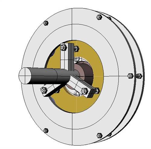
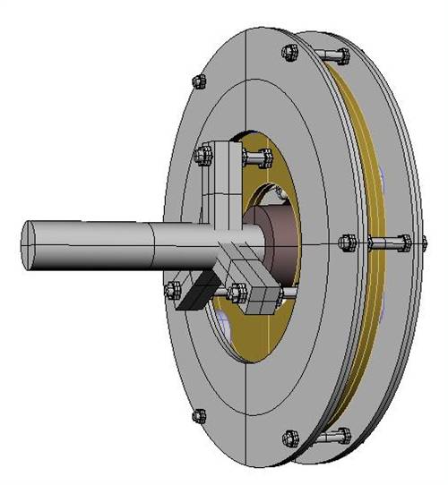
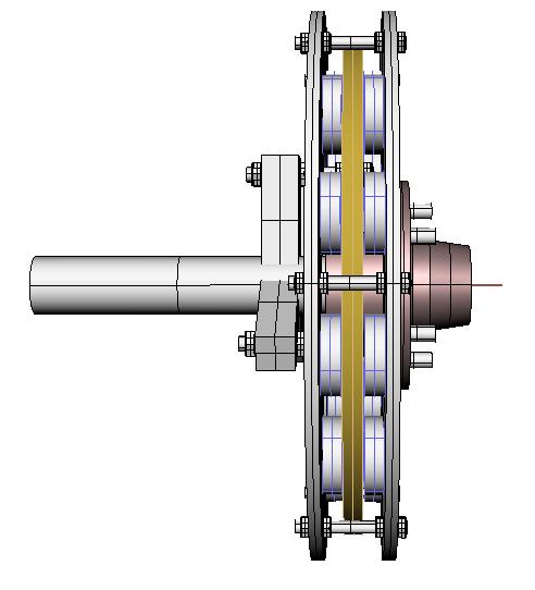
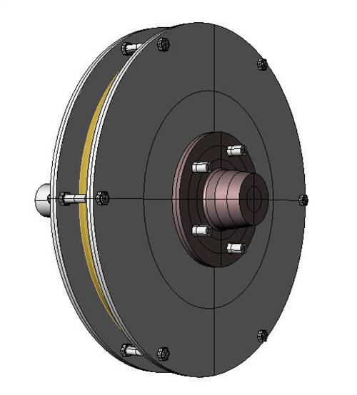
The best time to plant a tree was twenty years ago, the second best time is right now. JAQ |
||||
| Page 1 of 3 |
|||||
| The Back Shed's forum code is written, and hosted, in Australia. | © JAQ Software 2026 |
