
|
|
Forum Index : Other Stuff : 2 projects of interest on the go
| Author | Message | ||||
| Gizmo Admin Group Joined: 05/06/2004 Location: AustraliaPosts: 5031 |
Just a quick update on the progress of my axial flux. I've taken a lot of good advice from several forum members, and made a few changes to improve the strength and power capability of the design. I've gone back to the 12/9 design, thats 12 magnets per side, 9 coils. Basically it will use the same coil/magnet arangements as the conventional design used by Other Power and Hugh. The stator and magnet plates will have a lot more mounting points than my original drawings, allthread is cheap so might as well make it stronger, it wont cost any more and will add little to the weight. Besides, these magnets have enough force to destroy fingers permanetly, so I wont take shortcuts on the design to save a few grams. I've done the Cad work and will get the parts cut shortly, life has got in the way this last week so I had to hold off a few days. Glenn The best time to plant a tree was twenty years ago, the second best time is right now. JAQ |
||||
| VK4AYQ Guru Joined: 02/12/2009 Location: AustraliaPosts: 2539 |
Hi OZ Thanks very much for the in detail description, it has left my head swimming a bit as I am out of my comfort zone. After I read your description several times I think I am getting the feel for it a bit. One point of interest is the speed control of a VAWT is self regulating to a point as the efficiency drops off dramatically as speed increases, I have in the past built them and have never seen one exceed 150 rpm usual speed has been between 75 and 125 rpm using a 4 to 1 step up that gives a rpm range of 120 to 600 rpm the high revolution problem of a HAWT doesn't come into the picture. A rotor 3 meters in diameter and 4 meters high with six airfoil blades gave on a test 600+ ft pounds torque at 125 rpm gave maximum horsepower reading of 14.25 hp and at 75 rpm 3.6 hp this was at about 5 mph wind or at around 2.6 mtr sec. As the revs increased the torque dropped off but horsepower increased, by 150 rpm the drag of the device limited power out it wasn't tested in very high winds, over 40 mph as none came along during testing. As a safety the rotor was stopped and locked down in high winds. Why I was concerned about the magnets was that I can get neo 50 2x1x.5 magnets at a reasonable price so was going to order 60 of them for the generator. in reviewing you comments it appears that it would be better to have a rotor dia of 20 inches rather than the 36 inch I was thinking about, Also better as it would fit in my lathe for truing the plates up. The coils, I would need an AC output of 80 to 130 volts to work into the dc to dc converter. 27.5 to 31 volts to the battery bank. Your comments would be greatly appreciated. All the best Bob Foolin Around |
||||
niall1 Senior Member Joined: 20/11/2008 Location: IrelandPosts: 331 |
erm... the magnet size ratio to the wire thickness thing is confusing me a bit i think i can see how using much stronger bigger magnets to lower turns off thicker wire would lead to less resistance (heating) in the stator (less mechanical stress i suppose)...so this would kind off take the wear and tear off the stator ...or lessen the risk off burnout if you like ... now the prop matching to the alt is much better and it can break free a bit more ... and things start to happen ... but does this previous heating load provided by the power of the prop not just transfer itself to another medium i.e. batteries or dump which starts that whole cycle of resistance tolerance in the coils all over again ? dazzed and confused....  ...but fun all the same ...but fun all the same niall |
||||
| GWatPE Senior Member Joined: 01/09/2006 Location: AustraliaPosts: 2127 |
Hi Bob, Some of your data?? I quote from your own testing :- "A rotor 3 meters in diameter and 4 meters high with six airfoil blades gave on a test 600+ ft pounds torque at 125 rpm gave maximum horsepower reading of 14.25 hp and at 75 rpm 3.6 hp this was at about 5 mph wind or at around 2.6 mtr sec." Perhaps you could explain how you obtained the 3.6hp output power, from a rotor 3m dia and 4m high in winds of 2.5m/s. BTW the total energy in the wind at a velocity of 2.6m/s and a cross sectional area of 12m^2 is only, approx 170W. Perhaps, supplying the formulae you used for calculating the power can shed some light on this difference. Gordon. become more energy aware |
||||
| VK4AYQ Guru Joined: 02/12/2009 Location: AustraliaPosts: 2539 |
Hi Gordon The 3.6 hp was a typo error by late night brain death I have recalculated it to be 2.4 hp compared to nearly nothing from my design. Also we didn't have an accurate wind speed reading at such low wind speed it was estimated from a vain that frank designed for low speed. The windmill we tested was a experimental machine designed by an aeronautical engineer friend of mine unfortunately now deceased. The blade design was a six blade rotor with special aerofoil blades 12 inch cord with vortex generators on upper and lower surfaces of the aerofoil this nearly doubled the torque from the ones that I was building at the time. The horsepower was calculated by a 12 inch arm connected to a disk brake on the mill shaft to get foot pounds of torque. this was monitored by a shaft rev counter to monitor rpm with loading on the brake monitored so there was no constant reduction in rpm during the test the free running blades where faster than the test rpm, it was difficult to load the blades evenly at such slow rpm but it was done many times to get some meaningful average. The power formula used to calculate horsepower was; rpm x ftlb torque divided by 5252 At the time we did so many calculations that the formula has stuck in my head ever since. The mill produced nearly double the torque at low rpm to my design but as the rpm increased the the power increase dropped off but was still there, The significant factor I believe was the increase of power at low revs, I believe that the constant airspeed over the entire length of the blade is like having a constant TSR on a HAWT optimized by the vortex generators both sides of the blade this I believe gives twice the energy into the blade by extending the degrees of the arc that the blade is flying and creating lift. In a HAWT the working section of the blade is only 25 to 30 percent at ideal loading and TSR so the inner section is only there to hold the outer section to the hub in a non twisted blade it does however work to get the blade started and produces some power at low rpm. The fact that it does work as well as we know is the cube rule in wind velocity and the power transmitted therefrom His design for vortex generators is now used extensively on aircraft to reduce drag and increase lift, I believe it increases the effective cord of the aerofoil and increases the stall angle significantly hence a lot more lift energy from the aerofoil. I know from sad experience that the torque of the VAWWT is enormous even at relatively low revs and the stored energy in the rotor due to flywheel effect evens out the power produced by the rotor. Hope this clears things up a bit All the best Bob Foolin Around |
||||
| GWatPE Senior Member Joined: 01/09/2006 Location: AustraliaPosts: 2127 |
Hi Bob, I don't want to hijack this thread anymore. Perhaps a thread in windmills "validating power readings for a windmill" might be the go. Gordon. become more energy aware |
||||
oztules Guru Joined: 26/07/2007 Location: AustraliaPosts: 1686 |
Bob, 50 magnets will be enough to keep your device in check. The 20" plate if you can get it in the lathe is a fair size anyway. Work out how many magnets you can squeeze in to it with say a 1/2 magnet spacing between them. The runaway machines use only 24 of those. Magnet mass is everything with these things, so you have twice the forces to play with. A 24 pole machine with (18 coils) will be more than enough to keep your gadget under control. On that note, my 4m machine has a similar cross section of air to work with, and I must say, your test figures are about 60 times better than I can get at 2.5m/s. Allowing for Betz limits, and about 95% efficiency (bearing loss only in the alt at that power level), and 30% in the blades, I would be pleased to get 30 watts out from an available 36W with a CP of 3. I will leave it to you to work out what went wrong 
At 11m/s I can maybe get (optomistic here) 2kw out, but there is near 10kw of air going past, of which the max recoverable at the shaft is about 6kw (Betts level blades). With my blades probably 3kw recovered, >1kw for the stator, and <2kw for me. (a 40kmh wind has excellent cooling for the open stator  ).....(note to Gizmo, the part furled side angle on to the wind stator cools well on the front windward side, the front lee side gets little decent wind... that is another reason for the uneven cooking you see in those disaster pics..... 40km wind is a show stopper for a heat source (hair dryer coils without the fan disintegrate) ).....(note to Gizmo, the part furled side angle on to the wind stator cools well on the front windward side, the front lee side gets little decent wind... that is another reason for the uneven cooking you see in those disaster pics..... 40km wind is a show stopper for a heat source (hair dryer coils without the fan disintegrate)
Time will tell what yours actually does Bob, but getting the volts is no problem.... just more turns of thinner wire... and packing may be better too? To avoid abject disappointment, please research your expectations, as they seem to be very (and I mean very) optimistic to me. I suspect power levels very much lower than you think, so your alt will be overkill for that machine (just my opinion).. Niall [quote]but does this previous heating load provided by the power of the prop not just transfer itself to another medium i.e. batteries or dump which starts that whole cycle of resistance tolerance in the coils all over again ? [/quote] The heating of the stator is volts x current. The volts are the ("forcing volts" - the state of charge volts ) X current The forcing volts are the volts per rpm (open) X rpm. If we only change the stator R, then the TSR will change and rpm will drop a bit, and current will go up a bit, and volts lost in the stator will go down a bit... watts lost in the stator will go down as well. So as current = volts/resistance... then for the same voltage loss in the stator, and a lower resistance we can see higher currents.... more heat?? oops!! In reality, the rpm will be pulled back, and the volts lost will drop, over a smaller resistance, so for the same current in the stator now, the volts will be less, and so will the losses... ie smaller voltage loss over a smaller resistance, may keep the current the same, but the watts lower. For a zero resistance (super conductor) stator, the losses will be nill (Volts/zero so current will be infinite)........ but the mill won't ever get out of stall or past cut in....but we can add the necessary resistance on the ground in a water cooled jacket and then go for broke options.......
The cooler higher current stator will drive more electrons into the redox reaction in the cell... ie charge it faster. Some extra heat comes from this reaction, but mostly charging... ie turning your lead sulphate and water (flat state) into lead and lead di-oxide and sulphuric acid (charged state). It needs electrons to make this work, and your current is a measure of them going past your amp gauge and into the battery and driving that reaction..... more the merrier really.. Because of the dynamic nature of these things, it is not as simple as that, the TSR will change, and/or the prop size can be bigger now with lower R, you may bring it into stall, or you may stop over speed and pull it into line, or a combination of all the above...... and different ones at different wind speeds. What you can say, is your options are very much widened if the R is low. We can furl later (more power), we can add resistance if we need to break early stall (spread the heat around, not just in the stator), we can increase the prop size (more power, less wind) etc etc. Or put simply... WE STILL HAVE TO MATCH THE LOAD. You can't just add bigger mags to a well designed system (Hughs), and expect a vast improvement..... (unless it was held back by furling safety) So, thats not to say the little mags are no good. They actually let the prop run on a bit better, and in truth, get closer to the props best tsr. This allows your prop to behave better, and you can get much more power out than running in stall.... at low to low-medium power levels.....but it may fly to bits or burn up. It's all a balancing act. If you have MPPT, the higher resistance is not so much a problem, as the volts can rise in the stator, without the static load of the battery, the battery then is a dynamic impedance, and so current can remain constant at some point (input) if you wish, and just let the volts rise, and let the MPPT sort it out. With windmills, nothing is simple, but low R is a good thing if you want to chase power, or have options. This means more magnet and less turns for the same turns/volt. And a whole lot less panic when the real wind turns up 
.............oztules Village idiot...or... just another hack out of his depth |
||||
| niall1 Senior Member Joined: 20/11/2008 Location: IrelandPosts: 331 |
mm...interesting read...thanks for the detailed explanation ...so if take the bits i can understand ... , low r stators do leave the door ajar for other options
i,ve seen how adding a little resistance to the the line can completely change the character of the mill and how any stator heating can have its side effects long before burnout... i did see one stator that bowed over time ,almost enough to lose most off the airgap , i,m guessing heat plus a little bit off mounting bolt alignment didnt help this process.... just another possible suggestion on the axial...powder coating the rotors (if feasible)..seems really nice if you have all the machining (holes etc) done the coating will seal the rotors up completly , you can even very lightly sand it before you put the mags on , its pretty tough ps...the stator that bowed..now thinking back it didnt seem to have much (if any) cloth in it ...maybe that was more the problem niall |
||||
Downwind Guru Joined: 09/09/2009 Location: AustraliaPosts: 2333 |
Powder coating is next to useless if its on black metal out in the elements of nature. There is a Zinc powder undercoat that should be used for outdoor enviroments prior to the top coat but not all powdercoaters have or use the zinc as its costly and requires 2 cycles through the oven with including the top coat. I would think hot dip galv would be far better and it looks good to. Otherwise a good coat or 3 of epoxy paint would outlast powdercoat 10:1 and you can also coat the magnets, as you wont want to put the magnets through a 200C oven or you might have 2" round metal discs..not magnets. All resins go flexiable with heat even with glass in it, but glass gives a lot of strength to resin and it would be well advised to have as much glass in the stator as you can without effecting the thickness. As OZ said high temp resins is the go if you can get it. Pete. Sometimes it just works |
||||
| VK4AYQ Guru Joined: 02/12/2009 Location: AustraliaPosts: 2539 |
HI OZ Thanks for the comments on the plate and magnet situation, I can fit 30 magnets on each plate so may go that way, with the magnets set radially they will act as a turbine to some degree and flow some air over the stator for cooling, I was wondering if it would be worth mounting a set of lades around the outside of the rotor to augment air circulation? still have a lot to learn about this, I have a CD with Hugh piggots book on it somewhere but cant find it at the moment hence all the questions. All the best Bob Foolin Around |
||||
| niall1 Senior Member Joined: 20/11/2008 Location: IrelandPosts: 331 |
hi Pete we,ll have to agree to differ on the use of power coating...at least in my climate anyway ..  ...its used on lots off roofing steel here (agricultural out houses barns etc..) ...its used on lots off roofing steel here (agricultural out houses barns etc..)
this set are on their third year now...... 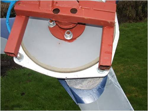
i give the frame a lick of red oxide to cover the rust when its down for checks i,m not saying it,l work for everyone really the only reason i tried it was the dans have been using it for a while now and seem to like it all food for thought ... ...i,ll keep an eye on them (edit.. erm...i mean the rotors not the dans... 
ps..maybe zinc was actually used on these ...i dont know niall |
||||
| Downwind Guru Joined: 09/09/2009 Location: AustraliaPosts: 2333 |
Hi Niall, I use to run the night shift at a powdercoater shop for a couple of years and do know a bit about it. The bottom line is the metal needs some form of rust proofing before powdercoating, this can be zinc powder, zinc plating, galv, or phosphate coating, to name a few or it will rust through the powdercoating as it is semi porous like many paints. There is many short cuts that the industry takes and heavy metal is one of the worst to do as it needs to be preheated and coated hot idealy or the plate wont reach enough temperture in the oven to give a good bond to the metal before the powder over bakes. There is under and over bake with the powder that effects the life of the coating as well. Powder coating is great stuff if the process is done right but you often wont know till its been in the weather for some time. So to drop your rotor off at the powdercoaters and say "paint this" might give a less than desired result with a little time in the weather. Its a brain dead job applying powder to metal bits so dont expect the painter to know what is required for you situation. (management should but not always) Pete. Sometimes it just works |
||||
| niall1 Senior Member Joined: 20/11/2008 Location: IrelandPosts: 331 |
hi Pete thanks for coming back with the info..i tried to read up a bit about it after... i,ve seen a utube where it shows its possible to powdercoat your own parts using a spare ? electric oven and the coating material,spray gun ..do you think this is feasible ? i hope this isnt too much off thread niall |
||||
| VK4AYQ Guru Joined: 02/12/2009 Location: AustraliaPosts: 2539 |
Hi Niall You can get a small coating system from ebay however like all powder coating systems the surface preparation is the main thing, you need a perfectly prepared uncontaminated surface to last the distance. Peter has commented on this from work experience, and the powder coated parts used in the pulp mill I am familiar with didn't last long because of incorrect preparation. We made a paper pulp mill with all sorts of corrosive liquids exposed to the steel work and found the best system was a 2 pac epoxy zinc rich primer and and 2 pac top coat I still have samples of this system exposed to the elements 30 years on and still a sound corrosion barrier. The surface should be sand blasted to remove all corrosion and mill scale, and if the part has been exposed to oil it needs a solvent wash otherwise the paint can separate, and no handling during the process as skin oil has the same effect on epoxy. For our applications in a non corrosive atmosphere a good marine paint and zinc rich primer will last for years and is cheap. You could also use a baked enamel or resin system as used in electric motors but the same preparation is necessary. If you want to not prepare well use a wire brush and heated linseed oil and a good enamel as a top coat.Warm the part to around 200 deg c before application to expel water from the surface of the part, old oven is good. Don't use the wife's good oven or you may end up sleeping in the workshop. All the best Bob Foolin Around |
||||
| Downwind Guru Joined: 09/09/2009 Location: AustraliaPosts: 2333 |
Hi Niall, To answer your question on home powder coating, No i would not bother trying to do it without the proper equipment. The powder is very fine and it is hard to get an even coat over all surfaces. The way is is applied in a shop is via a gun and as the powder leaves the nozzle of the gun a high voltage electrostatic charge is passed through the powder which charges the powder partials, a ground lead is attached to the metal work piece and the powder attracts to the metal and wraps around the bare surfaces. As the metal is coated the attraction becomes less so a even coat of powder is applied to all surfaces and sticks with the charged partials. It is then placed in a oven and heated to 200C and held at that temp for about 15 minutes, which melts the plastic powder into a smooth coating. Its removed from the oven and allowed to cool and the job is finished. I have seen a small setup where the powder is placed in a drum and a blower (vacuum cleaner in reverse) feeds air in underneath via a felt pad in the bottom this fluffs the powder into the air as a dust inside the drum. The metal is heated in a oven and then hung into the powder dust and the powder sticks to the hot metal. Then it is baked in the oven again. This works but not over well and it is hard to get an even coat without great globs of powder dripping from the work piece. I have often thought of setting up a small home powder coating system but the hassle and the poor results just aint worth the effort and its far cheaper to drive down the road and say paint this next time the colour is in the gun. To paint a stator is about 0.50 cents in powder cost and the rest is just oven space when something else is going through. If you dont mind a wait for the colour to be in the gun it works out cheap as to do a colour change for a small item wastes more powder than the item uses. Most shops have some standard colours that go through daily or weekly so it pays to ask and try to use one of them as its cheaper for all. Where i worked we use to run about 300 colours including the satin , gloss and textured finishes so colours were forever being rotated, so if i wanted Blaze Blue it might be a day or two before the colour went through, but so be it. Pete. Ps. Good advice from Bob about the wifes oven, as a new oven makes the cost of paying for the powdercoat job in the first place cheap and a more comfortable bed. Sometimes it just works |
||||
| niall1 Senior Member Joined: 20/11/2008 Location: IrelandPosts: 331 |
hi Bob , Pete thanks for the advise and detailed descriptions i,ll take it onboard and just use the oven for pizza i think...
i like your focus on preparation bob , i always worry a bit about gluing things after i,ve been let near them ,i usually handle things too much niall |
||||
