
|
|
Forum Index : Microcontroller and PC projects : PWM gaps?
| Page 1 of 5 |
|||||
| Author | Message | ||||
| Malibu Senior Member Joined: 07/07/2018 Location: AustraliaPosts: 261 |
G'day all, Another one that's left me scratching my head on PWM output... The story - I'm fiddling around with a small stepper motor trying to get it from REAL slow in 1/32 step mode, and ramp it up to fast in full step mode using a Pololu DRV8825 board from the MM+64 with output on PWM 1 I know from experience that stepper motors can be pretty cantankerous when first setting up, but not in this situation (well, not anymore! GRRRRRR!) I noticed a couple of step jumps a couple of times, so I spent a couple of days trying to figure out the hardware, my code and anything else I could think of. I couldn't even be sure that I was missing steps because it all happened so fast... But, I hooked up my PC-based DSO and ran this code (not the full code, just an extract with the relevant parts) 'A few definitions Const mStep=48, mDir=49, mEnable=50, mM2=51, mM1=52, mM0=53 'Set the pins setpin 49,dout setpin 50,dout setpin 51,dout setpin 52,dout setpin 53,dout 'Init the pin states Pin(mDir)=Low Pin(mEnable)=High Pin(mM2)=Low Pin(mM1)=Low Pin(mM0)=Low 'There's a Select case here ctrlval(cEnable)=true print "1/32" for i = Min to Max pin(mM0)=High:pin(mM1)=Low:pin(mM2)=High pwm 1,i,25 pause 10 next i print "1/16" for i = Min to Max pin(mM0)=Low:pin(mM1)=Low:pin(mM2)=High pwm 1,i,25 pause 10 next i print "1/8" for i = Min to Max pin(mM0)=High:pin(mM1)=High:pin(mM2)=Low pwm 1,i,25 pause 10 next i print "1/4" for i = Min to Max pin(mM0)=Low:pin(mM1)=High:pin(mM2)=Low pwm 1,i,25 pause 10 next i print "1/2" for i = Min to Max pin(mM0)=High:pin(mM1)=Low:pin(mM2)=Low pwm 1,i,25 pause 10 next i print "Full" for i = Min to Max pin(mM0)=Low:pin(mM1)=Low:pin(mM2)=Low pwm 1,i,25 pause 10 next i It took a few tries to get a capture, but this is perfect to explain what my question is... 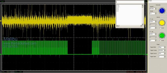 Top trace is the voltage/signal across the current sense resistor on the DRV8825. Bottom trace is the step input pulse from the MM. The MM Chat window is open so I can see what stage the loop is in. So, step mode has just gone from 1/4 to 1/2 on this capture, but right at the end of the 1/4 mode, the step pulses from the MM drop out completely (hard to see how many pulse are missing, but there's a lot). You can see by the 'patterns' on the top trace to the motor what the result is when the steps drop out. This is a random occurance, and only seems to happen during the ramp-up part of it, and at any step mode condition, but not while there is a set speed. The stepper has been happily running for 20 minutes now on a set speed (in full step mode) Sorry for the poor picture - it's a screen capture of a screen recording that was around 3 minutes long, and this was the clearest example on it. So, any ideas on what I'm doing wrong this time? John Edit - Sorry, I should have said this is running Min=600 & Max=1200 John |
||||
| Geoffg Guru Joined: 06/06/2011 Location: AustraliaPosts: 3355 |
When running at a set speed the PWM is entirely controlled by the PIC32 hardware, so you would expect it to keep running short of a power loss. However, when you are increasing/decreasing the speed MMBasic is calculating new parameters and writing them to the PIC32 hardware registers. The problem is that it is hard to come up with any reason why the output might stall during this. I have tested the PWM with ramp up/down many times and never seen this issue. The only cause that I can think of is that something is causing a PIC32 exception and forcing a reboot. If you have AUTORUN set your program would restart after 100ms which sort of matches your DSO trace. Checking the console output would confirm this. If that is not the cause I recommend that you create a simple program which just ramps the speed up/down and nothing else (ie, no timers, interrupts, etc). If it continues to stall I would then be able to setup a test bed with some more sophisticated test equipment and track it down. If the stalls stop then you can hunt through your bigger program for the cause. Geoff Geoff Graham - http://geoffg.net |
||||
| Malibu Senior Member Joined: 07/07/2018 Location: AustraliaPosts: 261 |
Thanks Geoff  Ok, with your advise - here's the 'new' version of the code... Option Explicit Const mDir=49, mEnable=50, mM2=51, mM1=52, mM0=53 Const High=1, Low=0 dim i as integer SetPin 49,dout SetPin 50,dout SetPin 51,dout SetPin 52,dout SetPin 53,dout Pin(mDir)=Low Pin(mEnable)=Low Pin(mM2)=Low Pin(mM1)=High Pin(mM0)=High Print "1/8 Step" Do Print "Ramp Up" For i = 50 To 2000 PWM 1,i,25 Pause 10 Next i Print "Ramp Down" For i = 2000 To 50 step -1 PWM 1,i,25 Pause 10 Next i loop ... and that's the entire code that I used. Just trying to keep the vars & const as I used them already, but did away with the pin changes inside the code. I've kept the uStep mode at 1/8th because it is the least likely to grate on my nerves (ie: the motor doesn't jump around the table at high or low speeds) Here's the result - 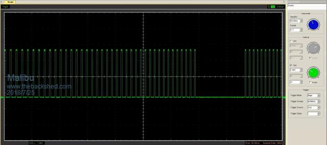 I haven't traced the output, only the PWM signal this time. As you say, it's around 100mS (closer to around 90mS by the looks of it), but it's still there. As an observation, it only seems to happen: A) On ramp up timing B) On the lower frequencies C) Again, with no regular position or amount of times. On saying it's 100ms second timing, it may be happening on a shorter Hz count, but my crappy DSO setup is just missing some of the skips and they might be happening too quick to have a noticeable effect on the RPM's. Is it possible that the "PAUSE" statements are causing the PWM to hang? I'm at a loss on this one, so I appreciate your help... John Edit: I just noticed when I thought about it, the first DSO picture and this current DSO picture is around the same time duration... so I guess it can't be frequency related. hmmmmm... John |
||||
| Geoffg Guru Joined: 06/06/2011 Location: AustraliaPosts: 3355 |
Thanks, it seems that this is the critical code: Do Print "Ramp Up" For i = 50 To 2000 PWM 1,i,25 Pause 10 Next i Print "Ramp Down" For i = 2000 To 50 step -1 PWM 1,i,25 Pause 10 Next i loop I will set it up and try to reproduce the fault (it could be a couple of days). BTW, what chip are you using (it looks like a 64 pin MM+) and what version of the firmware are you using? Finally, I cannot see how the PAUSE would have anything to do with it. Watch this space, Geoff Geoff Graham - http://geoffg.net |
||||
| Volhout Guru Joined: 05/03/2018 Location: NetherlandsPosts: 5859 |
Dear Malibu, In the MMbasic manual I read that the PWM has 0.1% resolution, translating into 1000 (1024) steps. You are writing values from 50 to 2000. Typically you could be looking at a wrap around of the PWM compare register between 1023 and 1024.. Regards, Volhout PicomiteVGA PETSCII ROBOTS |
||||
| Malibu Senior Member Joined: 07/07/2018 Location: AustraliaPosts: 261 |
Thanks Geoff, no worries... I've done enough coding to know that something like this may take a little searching! ...and to answer your questions, I'm using MM+E64 and the upload progress says "Micromite_Plus_V5.3 Version V5.4H detected" It's possible, but because there's no defined time that this happens, I can't see that would be an issue (I'll play with different frequency's tomorrow and check) I just had a thought - In the Micromite manual, it mentions "CPU Speed". Do I need to specify what the crystal frequency is? John |
||||
| Geoffg Guru Joined: 06/06/2011 Location: AustraliaPosts: 3355 |
No (I assume that it is 20MHz). I seem to remember this before. You are running Ver 4.04.08. The above is the MMEdit version number (not the Micromite's). There are two ways to tell the Micromite version number: - Reset the Micromite and check the copyright message on startup. - Run this at the command prompt: PRINT MM.VER Geoff Geoff Graham - http://geoffg.net |
||||
Azure Guru Joined: 09/11/2017 Location: AustraliaPosts: 446 |
Have you tried running the code and capturing the PWM output without the stepper board or motor connected, just the MM+64 and measure the PWM output. How are you powering the MM+64 and the stepper board. Are you able to monitor the MM+64 console output while it is running (to see if it is resetting and displaying the start up message)? If I get time tomorrow I will try and run the code on my MM+64 backpack and monitor the PWM output. Note: This approach is to try and isolate the PWM drive signal down to the minimum hardware and stil be able to reproduce the problem getting that break in output. |
||||
| Geoffg Guru Joined: 06/06/2011 Location: AustraliaPosts: 3355 |
Sorry, should have been Ver 5.04.08 Geoff Graham - http://geoffg.net |
||||
| Malibu Senior Member Joined: 07/07/2018 Location: AustraliaPosts: 261 |
It is... Excellent! I didn't know you could run commands direct from the console. It's 5.0408 Many times, and in both instances. When I first tried to find this problem, I thought it was the output of the driver board so did a days worth of hardware fault-finding on the output signals without the motor connected. It also happens over 4 different boards. 5V to the MM from a fixed 5V lab power supply, 24V to the stepper driver from the variable part of the same supply. There's no need to supply 5V to the board, it's taken from the motor supply (8-45 Volts) Presumably you mean the MM Chat window? There's no indication of anything wrong there. I use that with PRINT commands to see what stage the code is at (RampUP, RampDown, etc) and the only messages I get there are what I expect. I had a thought overnight - When I get myself fired up, I might try using SERVO on the same output and see what happens. I'll keep you posted! Thanks everyone John John |
||||
| Malibu Senior Member Joined: 07/07/2018 Location: AustraliaPosts: 261 |
Hmmmmm... Interesting! Here's the Servo code (The theory is that it's doing 'ALMOST' the same thing, so I should get close to the same results) In this, there no declarations, no EXPLICIT option or anything that might tie the MM up. Do 'Ramp Up For i = 20 To 1000 servo 1,i,0.5 Pause 0.2 Next i Servo 1, stop pause 1 'Ramp Down For i = 1000 To 20 step -1 servo 1,i,0.5 Pause 0.2 Next i servo 1, Stop pause 1 loop So, with the RAMP UP code commented out (ie: only ramping down), here's the results. 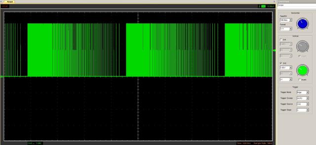 A nice and clean, sweeping waveform that makes sense... Comment out the RAMP DOWN code, and only run the RAMP UP and here's what happens. 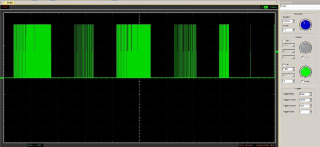 Looks like it's only on a frequency increase... So, here's the full code running... 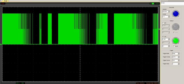 None of these DSO grabs have the DRV8825 board in place (and by default, the motor isn't running) When I first got this glitch I was pretty sure it was a hardware and/or wiring fault, or maybe I'm losing my marbles - but I'm starting to think it's neither... I'll keep playing and see what else I can come up with... I seriously need a COFFEE right now!!  John John |
||||
| Geoffg Guru Joined: 06/06/2011 Location: AustraliaPosts: 3355 |
Agghh, you need to read Getting Started with the Micromite Geoff Graham - http://geoffg.net |
||||
| Malibu Senior Member Joined: 07/07/2018 Location: AustraliaPosts: 261 |
Ooops, sorry Boss... I must have missed that line among the other 6 pdf's I have open to guide me! I stand suitably informed on 'Immediate Mode' now  John |
||||
| panky Guru Joined: 02/10/2012 Location: AustraliaPosts: 1120 |
Malibu, I could be wrong here (it's happened before  ), but in your code, the FOR ... NEXT loop time should work out at somewhere between 100 to 150 uSecs plus the PAUSE of 200uSecs for something in the region of 300 to 400uSecs total loop time. ), but in your code, the FOR ... NEXT loop time should work out at somewhere between 100 to 150 uSecs plus the PAUSE of 200uSecs for something in the region of 300 to 400uSecs total loop time.As the maximum freq you are setting is 2000Hz, (which has a period of 500uSecs), all the frequency settings you are sending the PWM controller will be less than 1 pulse width of the frequency you are setting? So , the PWM controller is being reset each time through the loop before it even completes 1 cycle? No idea if this would have any impact on stability but it seems a strange operation. As an asside, executing PWM 1,2000,50 from the command line and monitoring the PWM output at the constant frequency of 2000 shows no jitter on both a 100MHz Hantek DSO5102B digital scope and a 100MHz analogue CRO (Tektronix TAS465). Tested over a range of frequencies, all withn the same result. What I do see on the Hantek is more apparent noise and artifacts running through the display - I suspect these are sampling/quantitisation errors or noise. panky ... almost all of the Maximites, the MicromMites, the MM Extremes, the ArmMites, the PicoMite and loving it! |
||||
| Azure Guru Joined: 09/11/2017 Location: AustraliaPosts: 446 |
I have managed to do some testing. Using MM+64 LCD Backpack running 5.04.09. Running from USB power and nothing else connected to MM (except a microbridge board to communicate with the PC). Using the following code It ramps up and down with no break in the PWM pulse at any time. Monitored through multiple ramp up/down cycles. I checked it on my computer using bitscope and also on my Rigol 100MHz oscilloscope. Depending on scope setting it can have some trouble displaying it as a continuous stream, it is a sweeping frequency pulse train with a varying pulse width (% of frequency). I have tried varying the step increments (tried 1, 10, 50 and 100) making it ramp faster across the same frequency range), varying the PWM width (tried50%, 25%, 5% and 1%) and varying the pause time. All of these still had the PWM pulse running without any breaks or deadtime. So I think the PWM output is working fine, on 5.04.09 anyway. That I not to saying all is working properly with your stepper motor (because you know it's not). Something that came to mind while I was staring at scope displays and pondering on the problem was that the PWM on time is varying as a percentage (25%) of the frequency. So at the low ramp speed (i=50) the pulse will be fairly long and at high speed the pulse will be much shorter (i=2000). Not sure if this has anything to do with the motor not stepping smoothly, just wanted to mention it in case it turns on a light somewhere. |
||||
| Malibu Senior Member Joined: 07/07/2018 Location: AustraliaPosts: 261 |
Hi Panky, Ok, so what you're saying is that the PWM has got a new command before it's finished with the old one? An idea that I hadn't thought of, so I'll ponder that one. It could explain why it only happens on an increase in Hz and not a decrease. Nope, no problems with fixed frequencies here either. There seems to be quite a lot of noise for me too, but I just put that down to the Hantek USB CRO Azure, Same as what I have at the moment, but 5.04.08 (I even took out the LCD to be sure) Yeah, early on I was playing around with the % duty and even tried 1% at 20kHz. It was such a short signal, I think the capacitance in the circuit started to play havoc. The specs on the 8825 chip says a minimum pulse width of 1.9uS, so 25% duty should have it covered. No worries, thanks for that confirmation... I'll need to check a little more and see what else I can come up with. I'm sure Geoff is going to find the same thing as you, so thanks to all for your valued input... John John |
||||
| Azure Guru Joined: 09/11/2017 Location: AustraliaPosts: 446 |
I suppose it might be prudent to ask what you are trying to achieve. The reason I ask is a lot of stepper motor drive software will count steps and have routines which provide an angle or steps to position the motor accurately. Your code seems to be a (accurately controlled rpm) free running stepper motor driver to which you may add external controls (hall sensor, rotary encoder, limit switches, etc) to aid controlling the motor. If that is not what you intend then a different motor control method is needed than using PWM or SERVO as it does not keep track of elapsed the steps. PWM/SERVO will also not work if you need to go below their minimum frequency of 20Hz. I have made some extracts with notes from the manuals below that you may assist in developing your code. The most important one is the stepper controller minimum pulse width is 1.9us (0.0019ms). Calculations below show the test program creates pulses well over the minimum required. From the stepper controller chip spec: Max Step frequency 250KHz Microstepping selectable from full, 1/2, 1/4, 1/8, 1/16 and 1/32 steps Step pulse minimum 1.9us (for both high and low) and step active on rising edge Setup time for other pins before step pulse 650ns Note: 250KHz = 4us = 0.004ms, Theoretical max based on min pulses 2x1.9us ~ 263KHz. From MicroMite user manual: PWM Frequency range 20Hz to 500KHz Duty cycle as % of frequency accurate to 0.1% below 25KHz Notes: 20Hz = 50,000us = 50ms, 500KHz = 2us = 0.002ms So for test program lower and upper pwm high pulse @ 25% duty cycle 20Hz = 50,000us = 50ms @ 25% duty = 50,000us / 4 = 12,500us = 12.5ms pulse 2KHz = 500us = 0.5ms @ 25% duty 500us / 4 = 125us = 0.125ms pulse Both high pulses are longer than the min pulse width of 1.9us Both low pulses will be 3 times longer the above so also longer than 1.9us min Theoretical max PWM freq @ 25% duty is ~ 130KHz before min pulse is violated @ 1% duty cycle 20Hz = 50,000us = 50ms @ 1% duty = 50,000us / 100 = 500us = 0.5ms pulse 2KHz = 500us = 0.5ms @ 25% duty 500us / 100 = 5us = 0.005ms pulse Both would still be valid for stepper controller @ 1% duty cycle End Notes: SERVO Frequency range 20 to 1000Hz Pulse width in milliseconds, min 0.01ms to max 18.9ms Notes: So max frequency may not be high enough at 1KHz. 0.01ms = 10,000us so MM min pulse width is well above stepper controller min (1.9us) End Notes: SETTICK Period in ms, min 1 to max 2147483647 PULSE Width in ms, min 0.005 (5us) at 40MHz clock speed Notes: SETTICK min of 1ms = 1000Hz, so max freq using it will be 1KHz. PULSE can create a pulse and it's minimum is still with the stepper controller specs. I think there is also the option of creating a fast timer output pin and looping it back to an interrupt pin for, this culd then trigger a pulse in the interrupt routine. But that is another post altogether. |
||||
| jimbotron Regular Member Joined: 27/11/2013 Location: AustraliaPosts: 50 |
Looks like a race condition. To increase the frequency of the PWM you reduce the value of the Period register (PR). If the new value of the PR is less than the current count the PWM counter will continue to its maximum count causing a glitch. Imagine the PWM clock is 1MHz, duty cycle = 50% and the frequency is 100Hz. That means the PR would be set to 9,999. On each cycle the PWM counter counts up until it hits 9,999 then resets. The output is set to 1 on reset and to zero when the count hits 4,999. If the frequency is changed to 101 Hz then PR must be set to 9,900. If the PWM counter is currently at 9,950 then it has already missed the reset point and will continue until the counter overflows and returns to zero by itself resulting in a glitch. The lower the frequency the more likely you'll get a glitch. If you are decreasing the frequency the Period Register is increased so it is impossible for the PWM counter to be higher than the Period Register. The glitch is hard to detect, you need to set your scope to trigger in pulse mode then select a 0 pulse greater than 1ms. The PWM hardware allows duty cycle to be changed without problems as the new duty cycle value is buffered then loaded when the counter resets. However there is no buffer for the Period register. To avoid a glitch you'd need to change the code to wait until the PWM counter resets. |
||||
| Malibu Senior Member Joined: 07/07/2018 Location: AustraliaPosts: 261 |
'morning all, up early... all bleary eyed looking at some fresh ideas here. It's not about being prudent, it's just a damn good question to ask! (And probably something would have been easier to understand if I said first off )Ok, it's actually an idea for a coil winder. Simple enough, just a spindle (the motor shaft) holding a bobbin that a coil of wire will be wound onto (It's actually for guitar pickups) I went the idea of a stepper because I get better speed control at low RPM's. I started off testing with BLDC motors which are great for fast speed (12k RPM), but completely useless down low. With steppers, I've had from 1 to 1500RPM perfectly controlled. (There's torque issues as well, but that's another story!) The idea is speed control via a pot, ramp from 0 revs to the set revs at a defined rate. The issue with steppers is that in full step mode, the motor is noisy and clunky so low speeds are run in 1/32 mode. Micromode is no good at high speed so it needs to be change up through the stepmode from 1/32 to full step at the maximum speeds. Count control will be via a single pulse encoder by using a slotted wheel read by a slotted switch. Accurate to 1 turn, but that's good enough over a wind count of 11k turns. With steppers, I can also keep tally of the amount of steps taken for each turn pulse, and if there's a large enough discrepancy, I can fire an electronic shear-pin and stop the motor dead. The problem is that the transition between step modes can cause a tiny <clunk> in the motor which is why I've been experimenting with a sliding increase in frequencies. It made sense to me that PWM would be the best (and programably, the easiest)way to do it. I was just stumped on why this glitch popped up during the ramp up times... The two options I'm up early to try out today! I'll let you know how it goes. (I've got 6 windows to come out and get replaced today, so it might be a while) Jimbo, thanks for that explanation... that makes sense now as to WHY it's happening. I dredged up a few dusty memories of register operations in 16f84's and mentally put them into this context, and I can see the problem now! Thanks I think half my problem is the DSO - it's ok, but woefully lacking in some areas (I need a REAL one) I know I can get a smooth ramp with steppers, it's just finding the best way and I'll hit it hard for a while using the PULSE command (Fingers Crossed!) Thanks to everyone for the good advise and ideas!  John John |
||||
| Azure Guru Joined: 09/11/2017 Location: AustraliaPosts: 446 |
That explanation helps a lot. It clarifies a lot of what is needed. Do you have any idea what the maximum frequency you will need for the pulses (the most steps/sec you are likely to need). This will help determine the shortest timing resolution needed and options can be considered from there. It can be worked out by by coming up with the max coil RPM you need/want, multiplying by the motor steps per revolution and again by the microstep mode. If there are any pulleys/gearing their drive ratios need to also be included. The concern I mentioned was that while this is another option (also very clean and simple to do), I don't think you can use it with the settick command as it only goes up to 1KHz (which is the subject of the question above), you will proably need to explore the timer to external pin with loopback triggering an interrupt option. Re the glitch, we need to ask Geoff how the MM changes the frequency option for the PWM command. If it is somehow doing it cleanly in conjunction with a duty cycle reload then all might be good. Running the test code above did not show any glitching. I will try and set it up again and see if I can grab some footage of the ramp up and down to post. |
||||
| Page 1 of 5 |
|||||
| The Back Shed's forum code is written, and hosted, in Australia. | © JAQ Software 2026 |
