
|
|
Forum Index : Microcontroller and PC projects : PWM gaps?
| Author | Message | ||||
| Malibu Senior Member Joined: 07/07/2018 Location: AustraliaPosts: 260 |
Max Rpm's on the output shaft I'm looking at is around 1500 RPM... so it's 1500 div 60 * 200(PPS) gives me around 5kHz A stepper doing 1500 RPM is near on useless because there will be little torque, so I'll probably need a pulley ratio to drive a final shaft. Hence the testing  I looked at the SETTICK command briefly and a resolution of 1mS won't be good enough I don't think, but it was a busy day so didn't have much time to play. I was wondering earlier, what crystal frequency are you using on you MM? Maybe it has a bearing on the result. For now, I need to settle in and relax! With 6 double glazed windows out and in, a roomful of furniture moved (yet to be moved back) I'm done for! Is it Scotch-o-clock yet??  John John |
||||
| Geoffg Guru Joined: 06/06/2011 Location: AustraliaPosts: 3282 |
I can see the output stalling. Even this little program will cause it: Do PWM 1, 1000, 25 PWM 1, 1001, 25 Loop Each time the output stalls the signal is low (never high) and each time it lasts for 84mS regardless of the PWM frequency. The occurrence appears to be random. SERVO does the same. This is going to take some serious debugging as it involves the PIC32 hardware and its documentation (the latter is problematical). Leave it with me. Geoff Geoff Graham - http://geoffg.net |
||||
Azure Guru Joined: 09/11/2017 Location: AustraliaPosts: 446 |
Geoff, I'll setup my unit again and try that code as well. That way there will be more than 1 unit to verify things on. That probably answers my question about whether the PWM/SERVO freq is reloaded in sync with the signal pulse. How did you determine it was stalling (ie what are you using to measure it)? |
||||
| Geoffg Guru Joined: 06/06/2011 Location: AustraliaPosts: 3282 |
I think that the fix will be to generate a PIC32 interrupt when the timer count wraps back to zero and then update the timer's period register The code is already there for updating the SERVO pulse width. The question will be how much does this load down the CPU. I used a digital scope running a 10mS/div timebase. Geoff Graham - http://geoffg.net |
||||
| matherp Guru Joined: 11/12/2012 Location: United KingdomPosts: 10189 |
I'm away from home - can someone test this on the MMX and let me know results - thanks |
||||
| Malibu Senior Member Joined: 07/07/2018 Location: AustraliaPosts: 260 |
That's great Geoff (errr... figuratively speaking of course) I really appreciate you're looking into this. What you have described confirms what I saw happening on PWM and SERVO commands - I put the time at around 90ms, but that's probably my DSO setup. Just out of interest, does it happen with the other PWM and SERVO outputs? Please let me know if I can do something to assist John John |
||||
| matherp Guru Joined: 11/12/2012 Location: United KingdomPosts: 10189 |
Geoff I've just remembered something and I think I know the cause. The problem happens when you change the timer compare value to less than the current value of the timer. In this case the timer runs until it hits 0xFFFF and goes back to zero and then continues until it finally reaches the new value before triggering. The solution is to wait in the PWM command until the last cycle completes and then change the values early in the cycle (before the next pulse starts) - no interrupts needed. |
||||
| Malibu Senior Member Joined: 07/07/2018 Location: AustraliaPosts: 260 |
Morning all Some experimental observations from this morning... Here's the code I used (with my running notes as I monitored on the DSO) Option Explicit Dim i,j As integer DecreaseForLoop '<<--- Change here '<<============================================== Sub DecreaseForLoop Do For i = 100 To 20 Step -1 'Setup the next decreasing PWM frequency PWM 1,i,10 ' PWM output 1.. the new frequency.. Duty cycle ' NOTES: The first pulse duty cycle is alway 3.2 times longer than ' the next pulse duty cycle. ' Any higher than 30% duty, pulses 1 & 2 blend into a single wide pulse. For j = 1 To 400 ' j give the HZ time to settle ' higher value gives more pulse of the same Hz Next j Next i PWM 1, stop ' Stop the PWM to create a LOW gap in the signal Pause 100 ' A good size gap to easily see Loop End Sub '<<============================================== Sub IncreaseForLoop Do For i = 20 To 100 'Setup the next decreasing PWM frequency PWM 1,i,10 ' PWM output 1.. the current set Hz.. Duty cycle 'NOTES: The first pulse duty cycle width is always 10%(mS) of the 'set duty cycle. ie: Set=10,pulse=1mS.. Set=70,pulse=7mS For j = 1 To 400 'NOTES: Unrepeatable gaps, but are consistant with values Next j Next i PWM 1, stop ' Stop the PWM to create a 0V gap in the signal Pause 100 ' A good size gap to easily see Loop End Sub '<<============================================== Sub IncreasePause Do For i = 20 To 100 'Setup the next decreasing PWM frequency PWM 1,i,10 ' PWM output 1.. the current set Hz.. Duty cycle 'NOTES: The first pulse duty cycle width is always 10%(mS) of the 'set duty cycle. ie: Set=10,pulse=1mS.. Set=70,pulse=7mS Pause 10 'NOTES: Consistantly positioned gaps, consistant with the PAUSE value 'Doesn't appear random and can be repeatable 'PAUSE=10 looks perfect Next i PWM 1, stop ' Stop the PWM to create a 0V gap in the signal Pause 100 ' A good size gap to easily see Loop End Sub Running the "DecreaseForLoop" (which is for decreasing frequency with a j variable) I made a few observations: 1) The first pulse in the sequence is always 3.2 times the width of the second pulse. That's OK for my projected use (I only need the rising edge), but when the duty cycle setting reaches about 30%, the 1st and 2nd pulse merge into a single wide pulse. 2)Setting j to whatever value makes no difference to the final outcome, but it allows more PWM pulses over a longer total time period (more pulses of the same frequency. 3) this works perfectly (--- I used the j variable to introduce a delay as with the PAUSE statement, but to isolate if PAUSE was an issue, I tried a substitute ---) Running the "IncreaseForLoop" (Increasing frequency with a j variable) 1) The first pulse is always 10% (in mS) of the set value of the duty cycle. So, if I set the duty to 70, I see a 1st pulse width of 7mS... set it to 20%, I see 2mS. I didn't try a duty of 25 - presumable I would get 2.5mS, but it may turn out that the first pulse is an integer and will round up to 3mS? 2) Here it gets a little confusing! For the most part, I saw the gaps in the waveform, BUT, changing the j value would produce gaps in random positions but seemingly consistently across the wave form... So, if I enter a j value of 400 'this' time and run the code, the gap will be in a certain position right across the repeating waveform. I change j to 600 (for example) and I get different gap positions, consistent across all the waveform as long as I ran with 'that' value of 600. OK, change back to 400 and I get gaps in a DIFFERENT position to the last 400 I ran, but consistent across the waveform for as long as I ran that one! Sometimes I would change back and forth to all different values and eventually get back to a value of 400, and it would be a perfect signal! Are we all confused yet with my blabbering, because I sure was doing all this!?  So, running "IncreasePause" (just to triple check the PAUSE statement) 1) The same 10% duty cycle on the first pulse as above 2) PAUSE would create gaps in the waveform and, as above would be in a seemingly random position, but identical across the stream of waveforms. Change the PAUSE value, and I get a different position to the last, but consistent for the time I ran it. OK, set PAUSE to 10 and I watch the pattern, change to PAUSE 5 and I get a different pattern. Change back to PAUSE 10 - and I get the same gap position as the LAST time i ran with a PAUSE 10 statement! So, what does all this mean? I've NO idea  I just wanted to try and learn a bit more on what was happening, but now I'm more confused than ever!  Any interpretations on my observations? John John |
||||
| isochronic Guru Joined: 21/01/2012 Location: AustraliaPosts: 689 |
I know it is not the point, but it would be worth delegating the stepper drive to something like grbl, and sending the commands to it from the MM. |
||||
| Malibu Senior Member Joined: 07/07/2018 Location: AustraliaPosts: 260 |
Not sure about a GRBL... I didn't find a whole lot of info on it. The little bit I did find seems to be that it's a board that gets attached to a Uno uCOntroller and takes step/direction signals. Is that right? That's what I'm using here but it's a DRV8825 instead. The signals are all controlled by the MM+ which are Step, Direction, Enable and step modes. The 8825 board does all the hard yakka. (Unless I understand the GRBL wrong?) John |
||||
| MicroBlocks Guru Joined: 12/05/2012 Location: ThailandPosts: 2209 |
GRBL is a combination of an Arduino and the motor drivers. You then connect through a serial port and just send GCODE commands. GRBL also has ramp up and ramp down support which can be adjusted with parameters. Then it will just do it for you. Works pretty well and it is used in many DIY CNC machines. It also takes the really difficult nitty gritty parts out of your code. This is a blessing for many but if you are really into getting as close to the hardware then it takes away the challange. All depends on how much time and effort you want to put into which part of the development. Microblocks. Build with logic. |
||||
| Azure Guru Joined: 09/11/2017 Location: AustraliaPosts: 446 |
I have repeated the code mentioned before. I added a little to display what the waveform is doing and recorded a quick video of the computer screen showing the bitscope and MM console output. Here is the modified code (added variables for slow and fast and a pause at each end) Option Explicit Dim integer i, slow=20, fast=5000 Do Print "Ramp Up to "; fast; "Hz" For i = slow To fast Step 1 PWM 1,i,25 Pause 5 Next i Print "High Speed "; fast; "Hz" PWM 1, fast,25 Pause 5000 Print "Ramp Down to "; slow; "Hz" For i = fast To slow Step -1 PWM 1,i,25 Pause 5 Next i Print "Low Speed "; slow; "Hz" PWM 1, slow, 25 Pause 5000 Loop Here is the MM+64 BP PWM Test video (quickly recorded using my phone) so please bear with the rough handheld look, wanted to show it appears to be working in this setup with no glitches. |
||||
| isochronic Guru Joined: 21/01/2012 Location: AustraliaPosts: 689 |
To expand a bit, the genre is based on a board/s that reads simple ascii commands (g-code) on its serial input. The board/s then generates the pulses required for the stepper motors. The gcodes specify movements, origins, scales, arcs, etc and the system can look-ahead for accelerations and so on. Typically the boards have connections and power ics for three or so stepper motors (x,y,z) and also control some auxiliaries. Grbl itself uses compiled c on an arduino hardware base and shield, there are very similar systems utilising gcode on other platforms like pi linux etc as well. |
||||
| Malibu Senior Member Joined: 07/07/2018 Location: AustraliaPosts: 260 |
I doubt this will be presented as a 'good coding example', but as a temporary solution this seems to do the trick... option explicit dim i, j as integer '<< declares const min=20 '<< minimum frequency const max=5000 '<< maximum frequency setpin 49, inth, PulseInt '<< define the interrupt i = min '<< Set the initial minimum frequency j = 0 '<< set a dummy variable do pwm 1, min, 50 '<< start the PWM at minimum frequency do while i < max '<< Have we reached the maximum? j = j + 1 '<< fill in time while waiting loop '<< no, wait here pwm 1, stop '<< Stop the PWM i = min '<< reset the minimum j = 0 '<< reset the dummy variable pause 100 'Wait here and create a trace marker on the DSO loop '<< do it again Sub PulseInt '<< do this interrupt pwm 1, i, 50 '<< set the PWM to the valie of i i = i + 1 '<< increase i for next frequency end sub Simply put, the PWM is setup and run as you would expect, but the difference is that I've looped PWM output to an input declared as an interrupt. The initial frequency of the PWM is set to minimum and when the output goes high, it triggers the interrupt. Only THEN will the PWM parameters get changed to the next value. The idea is to write the PWM parameters at a point in time that the PIC can deal with it and it seems to work OK from 20Hz to 5KHz At least it gives me a smooth ramp up in frequency I can play with John |
||||
| Malibu Senior Member Joined: 07/07/2018 Location: AustraliaPosts: 260 |
Sorry, I meant to put up the resultant waveform... 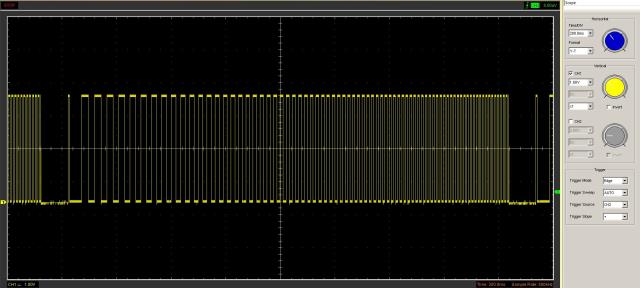 That's with MIN=20 & MAX=100 John |
||||
| viscomjim Guru Joined: 08/01/2014 Location: United StatesPosts: 925 |
Not related to original post, but I have used a few boards from here with great success using the micromite to send commands to run steppers. Works quite well and made my life a bit easier. Just send commands over serial. Even has feedback using serial or a "profile done" pin. Just a thought. |
||||
| Geoffg Guru Joined: 06/06/2011 Location: AustraliaPosts: 3282 |
I have updated the beta version to fix the PWM gaps issue (it is now at beta 5). It can be downloaded from: http://geoffg.net/micromite.html#Downloads Look for "Micromite Firmware V5.04.10 Beta Test Version" I have done a lot of testing on it and it runs smoothly on both ascending and descending frequencies. Please give it a run and let me know if you find anything else (fingers crossed that that will not happen). Geoff Geoff Graham - http://geoffg.net |
||||
| Malibu Senior Member Joined: 07/07/2018 Location: AustraliaPosts: 260 |
Thanks for the effort you put in Geoff!  I've hammered your new version pretty hard this morning and it's a BIG improvement! I started off with Ramp Up, Hold Speed, Ramp Down, Hold Speed in a DO: LOOP routine. I kept my eyes on the DSO and it all seemed good, but I could still hear a tiny <clunk> in the motor occasionally. I figured that it was probably my hardware and/or code that I had, but as I was going glassy-eyed watching the pulses, I THOUGHT that I saw a glitch... I whittled down the code and ran this... Const mStep=48, mDirection=50, mEnable=54 <<- Set Constants SetPin 50, dout <<-- Set Pins SetPin 51, dout SetPin 52, dout SetPin 53, dout SetPin 54, dout Pin(mDirection)=Low <<-- CW Rotation Pin(mEnable)=High <<-- Enable DRV882 Port (51,3)= &B101 <<-- Set to 1/32 Mode do for i = 20 to 25000 pwm 1, i, 50 pause 1 next i loop Most is to setup the DRV8825 board and I have limited the mode to 1/32 micro-stepping. I've also upped the PWM frequency to 25K, but that's because I've set 1/32 mode. I kept my eyes glued to the DSO, ready to pounce on the pause icon and finally here's the capture I got. 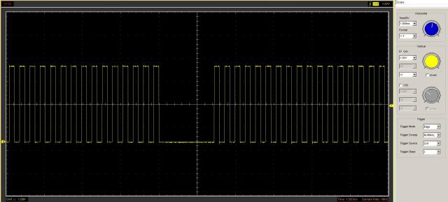 This is at around 3.7Khz and 1.45mS wide, but I've also captured 1.3mS at various other frequencies too Again, there seems to be no set pattern or frequency for the gap. Edit: Again, only low, never highs. With my USB DSO, it could be a limitation of that setup. It could also be my hardware/code, so I'll keep going and see where it ends up. No doubt, a big improvement on what was prior with a much smoother and sweeter sounding stepper motor. John |
||||
| Geoffg Guru Joined: 06/06/2011 Location: AustraliaPosts: 3282 |
Thanks, I can guess what is causing this one and it is a bit more complicated. I will have a go at it over the next day or two and report back. Geoff Graham - http://geoffg.net |
||||
| Malibu Senior Member Joined: 07/07/2018 Location: AustraliaPosts: 260 |
A little more... Here's the code - an adaption of your test code Geoff Do PWM 1, 3000, 25 PWM 1, 3010, 25 Loop That should be (3000/200PPR)*60 = 900RPM... confirmed by the digital tacho. While I run the code, the motor goes crazy by stopping, starting, hunt forward, run reverse, stop, hunt backward... and so on (It's hard to explain, but it does what motors shouldn't do!) So, clicking ^C in MMchat, will do one of two things: 1) the Motor runs perfectly sweet. 2) the Motor squeals in a stalled position. Whichever one happens, the frequency continues smooth and steady at 3Khz and physically, the motor runs according to what it was doing when I actually click ^C. Still fiddling - I'll keep you updated! John |
||||
| The Back Shed's forum code is written, and hosted, in Australia. | © JAQ Software 2025 |
