
|
|
Forum Index : Microcontroller and PC projects : CMM2 graphics examples and explanation
| Page 1 of 2 |
|||||
| Author | Message | ||||
| matherp Guru Joined: 11/12/2012 Location: United KingdomPosts: 11698 |
I thought I'd start a thread to try and explain the concepts behind the CMM2 graphics and give some annotated examples of how to use the facilities in the CMM2. I'm sure Mauro will chime in and then perhaps some of what is in the thread can form the basis of a graphics manual of some sort. This first post will cover the basics of how the graphics are generated and work. Some of the STM32 chips, including the STM32H743IIT6 that we are using, have an on chip graphics controller (called the LTDC = Lcd Tft Display Controller) This is programmed to read from a defined area of memory at a specific rate and write the data to a set of I/O pins. In our case the I/O pins are connected to the resistors that make up the three R2R DACs on the CMM2 motherboard and these create the analogue VGA signals. In addition the LTDC is programmed to create the HSync and VSync signals which tell the monitor that we have reached the end of a line or and of a page. All these signals must waggle at a rate determined by the a defined VGA specification depending on the resolution required. In the case of the 800x600 display memory is being read at a rate of 40MHz, the line rate is 37.8787KHz and the frame rate is 60Hz The important point about the LTDC is that all this happens without any use of the processor once the controller has been initialised. It is basically a continuous circular DMA (Direct Memory Access). Of course this isn't completely free as it does consume memory bandwidth even though the processor isn't involved. So to get something onto the screen all we have to do is write to the area of memory that the LTDC is reading and something will appear on the screen. For performance reasons the best memory to use is the STM32H743IIT6's internal memory and 512KB of this is allocated to the main video memory. In addition I have allocated 3MB of the 8MB SDRAM memory (this is the chip on the back of the Waveshare PCB) to use for graphics. So we have 3.5MB of memory available for graphics, 512KB is located at memory address &H24000000 and 3MB at address &HD0000000. We will see in the next section how we can poke this memory to write things on the screen. However, we need one more concept before starting to explore how to use this memory - the Colour LookUp Table or CLUT. The default resolution of the CMM2 is 800x600 with an 8-bit colour depth so the screen uses 480,000 bytes out of the 512 KBytes available in the processors internal video memory. However, we need to drive 16 data lines not just 8 and the way this happens is that the LTDC takes each 8-bit value in turn as it reads memory and uses it as an index to a table of 16-bit values (the CLUT). This table is initialised by the CMM2 firmware to sensible values to give good colour coverage but can be changed from within MMBasic using the MAP command (subject for another post). OK, so we know that in 800x600x8 resolution the screen is using 480KB of memory starting at &H24000000. This memory is organised exactly as you would expect. The first 800 bytes are the top line of the display starting at the top left hand corner. The second 800 bytes are the second line of the display. and the 480,000th byte is the bottom right of the display. So lets draw a diagonal line on the display to prove this. pix%=&H24000000 for i%=0 to 599 j%=i%*800+i% poke byte pix%+j%,255 next i% 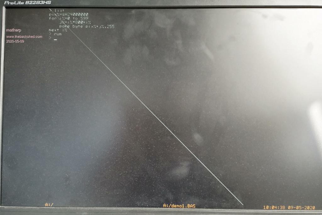 Note how the line just writes across anything already on the screen. It is a bit silly having to memorise &H24000000 so the CMM2 includes a built in function to give it to us pix%=mm.info(page address 0) for i%=0 to 599 j%=i%*800+i% poke byte pix%+j%,255 next i% Of course we could have done the same thing using the command line 0,0,599,599 Internally in the CMM2 firmware the LINE command is doing exactly what we did with POKE. And, of course, all the basic graphics commands are doing the same thing - writing to memory in order to construct the requested shapes. Next post I will explore graphics pages and how they allow us to do some of the magic but if you properly understand the above then everything else should be easy. |
||||
| matherp Guru Joined: 11/12/2012 Location: United KingdomPosts: 11698 |
Graphics pages In the previous post we saw that writing to the memory identified by MM.INFO(PAGE ADDRESS 0) displays immediately on the screen. In fact the CMM2 always and only ever shows on its display the information in the memory starting at MM.INFO(PAGE ADDRESS 0) (NB: not true in 12-bit colour depth but that is a subject for a much later post). This is important as it underpins the explanations below. Drawing the line using POKE in the previous example took 12mSec on my 400MHz CMM2. This is fast enough that the act of drawing didn't create any strange visual effects. However, if we slow it down by adding a pause we can see the line drawing across the screen as it now takes 614mSec. pix%=mm.info(page address 0) for i%=0 to 599 Ā j%=i%*800+i% Ā poke byte pix%+j%,255 Ā pause 1 next i% This is a trivial example but lots of graphically intensive activities do take "real" time to complete and it may be that we don't want to see the update taking place but would rather move from one static image to another. A rather better example would be displaying a BMP image. BMP files are uncompressed so they are large and take time to load as they wait for the SDcard to read. They also load from the bottom up which is slightly strange. A full colour 800x600 BMP takes just less than a second to load. If we type ? MM.INFO(MAX PAGES) we get the answer 6. This says that in our current 800x600 resolution the 3.5MB of video memory is being split into 7 chunks, numbered 0 to 6. We know that Page 0 is what is being displayed on the screen and it will always be page 0 that is displayed. However, we don't need to write to page 0. MM.INFO(MAX PAGES) tells us that in 800x600x8 video mode we have 7 video pages at our disposal. We can see where they are in memory using MM.INFO(PAGE ADDRESS n) for i=0 to 6:print hex$(mm.info(page address i)):next i 24000000 D0000000 D0080000 D0100000 D0180000 D0200000 D0280000 We can tell the CMM2 which page to use for writing using the command PAGE WRITE n So lets type PAGE WRITE 1 at the command line OH NO!!!! The status line just disappeared, the cursor disappeared, when I type nothing happens All console output is now being directed to a different area of memory starting at &HD0000000. Luckily any error or typing Ctrl-C will bring things back. PAGE WRITE isn't very useful at the command line but can be used. How about? PAGE WRITE 1:LOAD BMP "mybmp":PAGE WRITE 0 This time my cursor came back OK after about a second but no picture Now type: PAGE COPY 1 TO 0 Instantly the picture will appear (actually it takes about 4mSec) Now we can use this to create a BMP slideshow where each image instantaneously replaces the previous one. page write 1 a$=dir$("*.bmp") do Ā Āload bmp a$ Ā Āpage copy 1 to 0 Ā Āpause 1000 Ā Āa$=dir$() loop while a$<>"" The PAGE COPY command is very highly optimised to run as fast as possible. It also has an optional parameter which is documented in the user manual I: means do the copy immediately. ĀIt is the defualt and most efficient but risks causing screen artefacts B: means wait until the next frame blanking and then do the copy. ĀIt is the least efficient but is absolutely determinate in its effect and no screen artefacts will ever be seen. D: means carry on processing the next command and do the copy in the background when the next frame blanking occurs. ĀThis is efficient but must be used with care as subsequent drawing commands may or may not be included in the copy depending on the timing of the next screen blanking In a future post I will improve the slideshow program by having one image replace the previous by slowly scrolling in from the right hand side using another of the PAGE command functions but to summarize: Multiple pages allow you to store and/or construct complex images without any visible screen artifacts. PAGE COPY allows you to pretty much instantaneously replace what is being seen with a new image with no artifacts. PAGE COPY is very fast. For example in 320x240x8 graphics mode it takes less than 0.3mSec Edited 2020-05-09 20:47 by matherp |
||||
| matherp Guru Joined: 11/12/2012 Location: United KingdomPosts: 11698 |
In this post we look more at the Colour LookUp Table (CLUT) and the MAP command and function and use them to create a rotating colour disk 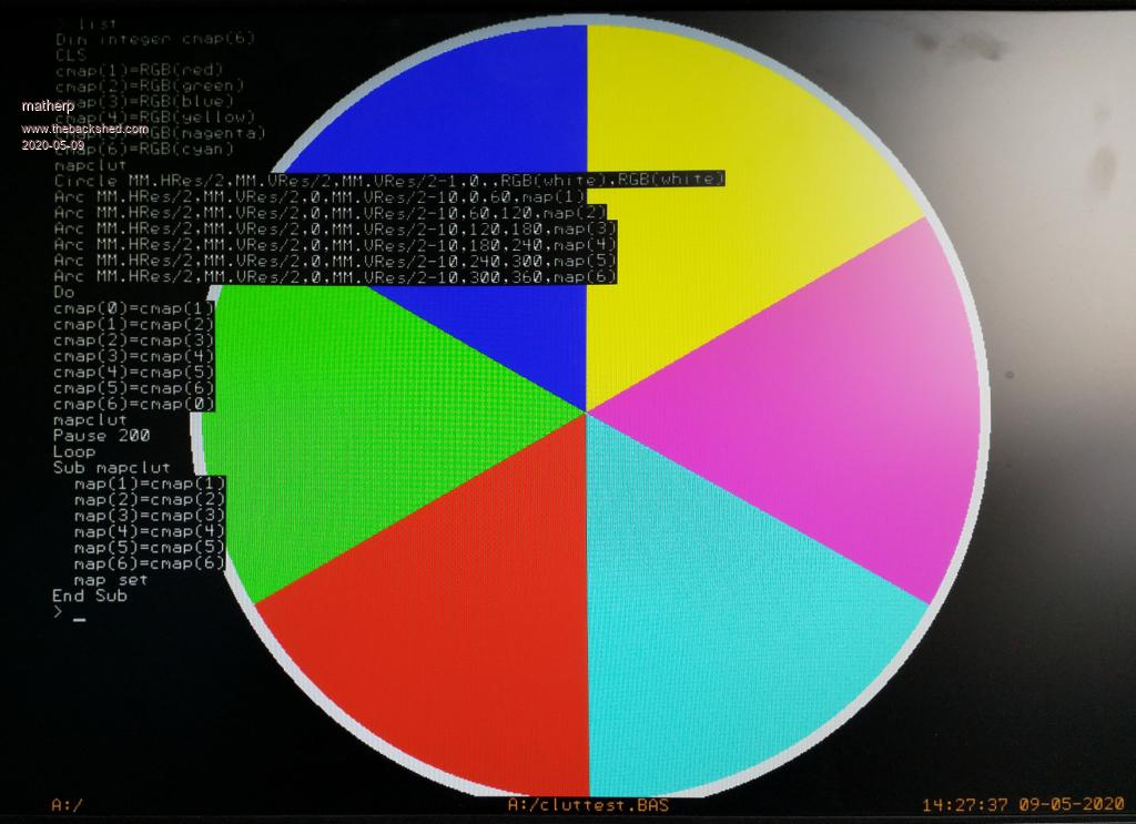 As explained earlier, 8-bit colour modes use a lookup table to convert from a single byte of information to the RGB565 pixel that will be displayed. In the CMM2 firmware the 8-bits are treated as a RGB332 pixel and are mapped to the most appropriate RGB565 value. However, we can override this using the MAP command. Normally a pixel that is set to zero would mean that it would be black on the screen but if we use the commands MAP(0)=RGB(RED) MAP SET Then every "black" pixel on the display will instantly turn red. Actually it isn't quite instant as the MAP SET command waits for the next frame blanking period before making the change. So MAP(n)=colour primes the colour change and MAP SET enacts it. This allows us to change a number of colours simultaneously by using multiple MAP(n)=colour commands and then a single MAP SET. To use our new colours in a drawing command we use the MAP(n) function. So for example if we type MAP(134)=RGB(148,73,66) to get some particular shade then to use that colour we would reference it as MAP(134) e.g. MAP(134)=RGB(149,73,66) MAP SET TEXT MM.HRES\2, MM.VRES\2,"Hello",CM,,5,map(134) This would display the text in a dark brown colour. If we then typed MAP(134)=RGB(BLUE) MAP SET The text would immediately turn blue as would any other pixels on the display set to 134. There a couple of other MAP commands MAP MAXIMITE sets the CLUT to mimic the colours of the original Colour Maximite. i.e. 0-7 are the Maximite primary colours. MAP RESET restores the original RGB332 mapping Now lets look at using the MAP command to create the colour wheel above ' Set up an array to hold the colour mappings we are going to use Dim integer cmap(6) 'Clear the screen CLS 'Set up 6 colours in the array cmap(1)=RGB(red) cmap(2)=RGB(green) cmap(3)=RGB(blue) cmap(4)=RGB(yellow) cmap(5)=RGB(magenta) cmap(6)=RGB(cyan) ' Do an initial update of the CLUT to set up our colours mapclut 'Display an outer circle in white Circle MM.HRes/2,MM.VRes/2,MM.VRes/2-1,0,,RGB(white),RGB(white) ' Now draw a simple colour pie chart using our new colours with the ARC command Arc MM.HRes/2,MM.VRes/2,0,MM.VRes/2-10,0,60,map(1) Arc MM.HRes/2,MM.VRes/2,0,MM.VRes/2-10,60,120,map(2) Arc MM.HRes/2,MM.VRes/2,0,MM.VRes/2-10,120,180,map(3) Arc MM.HRes/2,MM.VRes/2,0,MM.VRes/2-10,180,240,map(4) Arc MM.HRes/2,MM.VRes/2,0,MM.VRes/2-10,240,300,map(5) Arc MM.HRes/2,MM.VRes/2,0,MM.VRes/2-10,300,360,map(6) ' Start a never ending loop Do 'each time round the loop move the colours in our array one place to the left ' Use array element 0 to store the first element that is going to be at the end Ā cmap(0)=cmap(1) Ā cmap(1)=cmap(2) Ā cmap(2)=cmap(3) Ā cmap(3)=cmap(4) Ā cmap(4)=cmap(5) Ā cmap(5)=cmap(6) Ā cmap(6)=cmap(0) ' reset the colour map Ā mapclut ' pause so we can see the change Ā Pause 200 Loop 'This subroutine updates the colour map for the colours we are using ' Āset map positions 1 to 6 to the new colours ' Āthen apply the change Sub mapclut Āmap(1)=cmap(1) Āmap(2)=cmap(2) Āmap(3)=cmap(3) Āmap(4)=cmap(4) Āmap(5)=cmap(5) Āmap(6)=cmap(6) Āmap set End Sub > Next post we are going to look at BLIT. Sounds complex? Actually all it is is a memory to memory copy - nothing more, but perhaps the most powerful tool in the graphics arsenal. Edited 2020-05-10 00:19 by matherp |
||||
| matherp Guru Joined: 11/12/2012 Location: United KingdomPosts: 11698 |
BLIT Blit does a memory to memory copy. End of lesson. Well perhaps not but that is all it is doing behind the scenes. Lets look at the BLIT syntax BLIT x1, y1, x2, y2, w, h [, page] [,orientation] This says copy part of the image which has a top left position of x1,y1, a width of w, and a height of h to a new position with a top left position of x2, y2. An example: ' Draw a simple shape on the screen CLS box 100,100,100,100,5,rgb(red),rgb(blue) 'copy the box to a new location with a top left corner at 300,300 blit 100,100,300,300,100,100 By the way that copy took 88 microseconds which equals 100*100/0.000088=113 Mbytes/Sec. BLIT is very fast Thinking back to the first post, we know what was just happening and we could have done the copy in Basic CLS box 100,100,100,100,5,rgb(red),rgb(blue) 'copy the box to a new location with a top left corner at 300,300 page_address%=mm.info(page address 0) x1%=100 y1%=100 x2%=200 y2%=200 w%=100 h%=100 for y%= 0 to h%-1 for x%= 0 to w%-1 'calculate the address of the source pixel pix_in%=MM.HRES * (y% + y1%)+ x1% + x% + page_address% 'calculate the address of the destination pixel pix_out%=MM.HRES * (y% + y2%)+ x2% + x% + page_address% 'copy the pixel poke byte pix_out%, peek(byte pix_in%) next x% next y% This takes just over half a second - BLIT is faster!!! Try the following commands: timer=0:blit 100,100,300,300,100,100:?timer timer=0:blit 100,100,301,301,100,100:?timer timer=0:blit 101,101,301,301,100,100:?timer The timings I get are 88uSec, 155uSec, and 214uSec. The STM32 is much faster when it can copy data that is aligned on 4 byte boundaries. For most applications this won't matter but for a very high performance game it is something to take into account. Now lets explore the orientation parameter of the BLIT command. This is most easily explained by a couple of examples CLS ' draw a large number 4 text 100,100,"4",,6,,rgb(red),rgb(blue) ' copy the "4" but mirror it left to right blit 100,100,200,100,32,50,,1 ' copy the "4" but mirror it top to bottom blit 100,100,100,200,32,50,,2 ' copy the "4" but mirror it top to bottom and left to right (rotate 180) blit 100,100,200,200,32,50,,3 do:loop 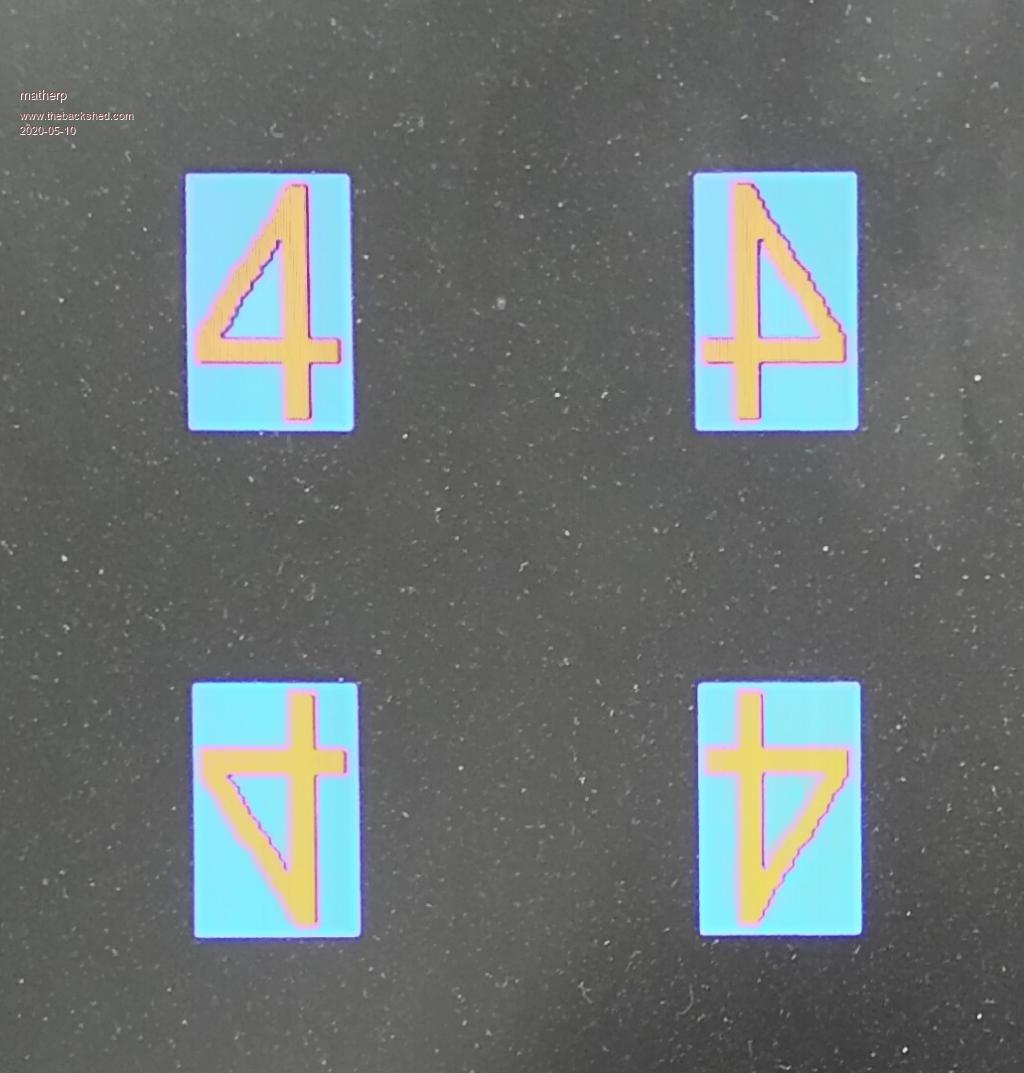 CLS ' draw a large number 4 text 100,100,"4",,6,,rgb(red) ' draw a colour box box 180,180,72,90,0,rgb(blue),rgb(blue) ' move the text but only non-transparent (non-zero) pixels blit 100,100,200,200,32,50,,4 do:loop 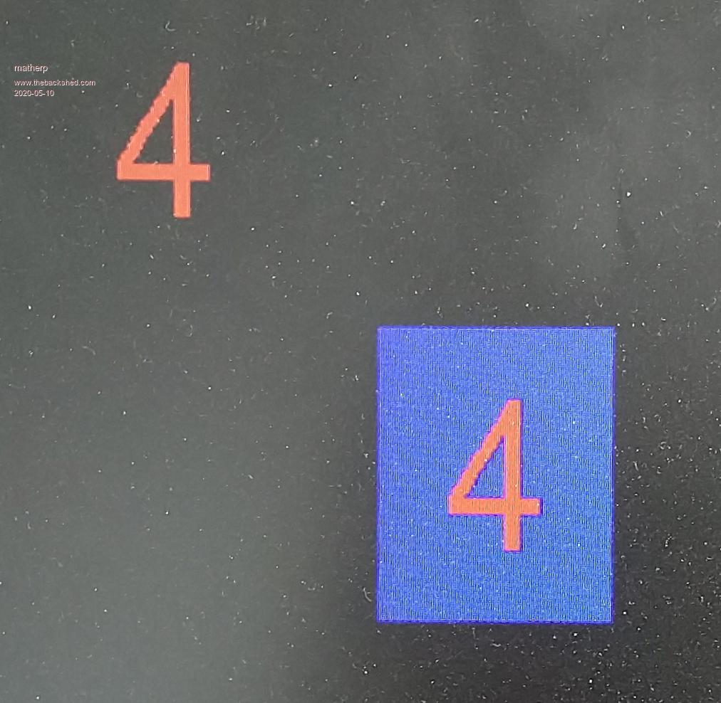 Of course the orientation bits can combined in any combination If you BLIT from one area to another that overlaps it then BLIT is clever enough to understand this and deal with it by buffering the original and then writing out the new version. Up to now we have ignored the page parameter in BLIT but this is perhaps the most powerful aspect of the command. As we saw in a previous post we can use PAGE WRITE to set drawing output to any of the video pages available but we will always see what is in page 0. The page parameter in BLIT specifies the page that BLIT will read from and then it will write to the page specified by PAGE WRITE. Another example needed. We can use BLIT to create the basis of a sliding block puzzle 'set output to page 1 page write 1 ' clear page 1 to blue cls rgb(blue) 'write the numbers 1 to 8 spaced 50 pixels apart ' font 6 is 32x50 pixels for i = 1 to 8 text i*50+10,0,str$(i),,6,,rgb(red),-1 next i 'now we want to randomize the numbers for our grid including the missing one dim r(8)=(9,9,9,9,9,9,9,9,9) 'create an array to hold the positions for filled=0 to 8 do test=rnd(8) 'get a random number between 0 and 8 for j=0 to filled 'check all the filled cells to see if we have already used this number if r(j)=test then test=9 ' if yes then set no-good next j if test<>9 then r(filled)=test 'if OK then store the number loop while r(filled)=9 'loop until that cell is filled next filled 'Now we will go back to the view page page write 0 cls ' create a background for the grid box 100,100,170,170,0,rgb(green),rgb(green) ' now copy the randomised numbers into our grid for x=0 to 2 for y=0 to 2 'get the x position of the randomised number in page 1 xsource = r(x * 3 + y) * 50 ' blit the number from page 1 to page 0 blit xsource, 0, x * 55 + 105, y * 55 + 105, 50, 50, 1 next y next x 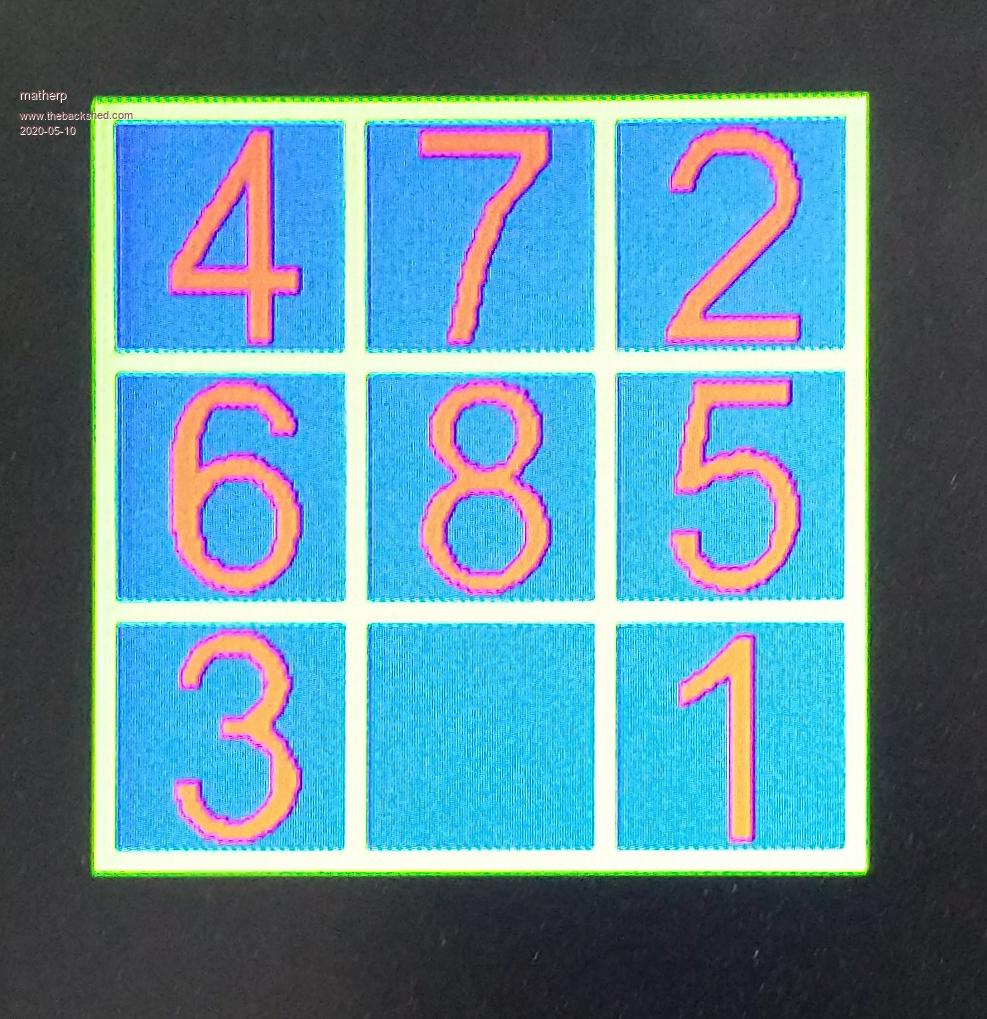 This simplistic example is how Mauro weaves his magic. You can create any useful graphics you want on one or more hidden graphics pages. Then you can use BLIT to move parts of the image between them, including potentially onto page 0. And, of course, you can mirror or rotate the parts of the image as you move them. There are two more BLIT commands in the manual: BLIT READ and BLIT WRITE, but we will leave these until we deal with sprites. Next post will look at the various graphics modes supported by the CMM2. |
||||
TassyJim Guru Joined: 07/08/2011 Location: AustraliaPosts: 6555 |
Spurred on by Peters great tutorials, I decide to do some comparisons between the various ways of drawing the cells in the "Game of Life" I modified my version of the game to repeat the same set using different drawing methods. I also did one run with all the calculations but no drawing. This was used as the base. Time to draw approximately 200 cells: 1. Use TEXT to draw a single character 8mS 2. Use BLIT to copy from a background page 10mS 3. Draw the cell using CIRCLE 13mS 4. use BLIT to WRITE pre-prepared sprites 14mS As a comparison, the rest of the routine took 217mS so the graphics is only a small part of the speed considerations. The fastest was TEXT so for graphics with a single colour, a defined font would be a good choice. Next is BLIT between areas the screen. This can be full colour images so would give the best looking display. Next is drawing directly for each cell. Simple to do for basic shapes. Last was using BLIT WRITE (saved SPRITES). This method does do transparency so might be the right choice if that's of interest. BLIT is nearly as fast as TEXT but has the advantage of full colour. Jim VK7JH MMedit |
||||
| matherp Guru Joined: 11/12/2012 Location: United KingdomPosts: 11698 |
Graphics modes This post will introduce the 5 graphics resolutions on the CMM2 and the three colour depths in more detail and the use of the MODE command. I will mention the 12-bit modes but will reserve a full explanation of these until a separate tutorial. Also, still to come in this series is more on the PAGE command, using the basic graphics in a more efficient way and, of course, sprites. A lot of this post will be slightly theoretical, but the more you understand what is going on under the cover of the CMM2 the better you will be able to make the most of its capabilities. Lets start by being a VGA monitor and asking it to show the Display Information for the signal it is receiving. This isn't affected by the colour depth. Mode 1 (800x600) : Monitor sees 800x600 @ 60Hz Mode 2 (640x400) : Monitor sees 640x480 @ 75Hz Mode 3 (320x200) : Monitor sees 640x480 @ 75Hz Mode 4 (480x432) : Monitor sees 640x480 @ 75Hz Mode 5 (240x216) : Monitor sees 640x480 @ 75Hz That looks a bit odd - lets explain. VGA monitors, particularly modern TFT types, have a limited range of signal timings that they will accept and sync up properly. We have chosen to use just two that are supported by all monitors. 800x600 @ 60Hz needs a 40MHz pixel clock. 640x480@75Hz needs a 31.5MHz pixel clock. All other timings, vertical sync and horizontal sync are defined as a multiple of the underlying clock period. Before going into this in more detail I'll answer the question - why 640x400 and not 640x480? In the first post I explained the way memory is used for the graphics pages and that 800x600 resolution with 1 byte per pixel uses 480,000 out of 512K (512*1024=524288) bytes of the fastest memory. 640x480 would only use 307,200 bytes so no problem BUT 640x480 with 16-bit colour would use 614,400 bytes - more than we have available. 640x400x2 = 512,000 just inside the 512K limit allowing full colour images to be displayed from the fastest memory. Moreover, the main retro computers Commodore64, Amiga, Atari-ST all used 320x200 as their main graphics resolution, the same as our mode 3 and 640x400 is exactly double this. But, I hear you say, The manual says the CMM2 supports 800x600x16-bit resolution amongst others. Yes, but in this case the first megabyte of the 3 MBytes of SDRAM is used as video display memory - page 0. The SDRAM isn't as fast as the internal memory but in most cases works perfectly well in this mode and it is great for displaying pictures. With a pixel clock at 40MHz and 2 bytes per pixel the LTDC is reading that memory at 80Mbytes/second. Even more extreme is 12-bit mode. Without going into the explanation Āhere 12-bit mode uses 4 bytes per pixel so 800x600x32-bit now needs memory to be read at 160Mbytes/second and uses 2Mbyte of SDRAM! The SDRAM is also used for MMBasic arrays and things like buffers for playing MP3 and FLAC files. If you set the video mode to 800x600 12-bit resolution and play a MP3 file and run a program then occasionally the monitor may flicker or lose sync. The extent to which this happens is very much monitor dependent and while there may be no issue on your monitor there may be for other people. For this reason the graphics modes that use the SDRAM as the main display memory are only enabled if you execute OPTION MODES UNLOCKED and you are discouraged from distributing programs that use these modes. Back to the main story. Supported resolutions Mode 1 displays 800x600 pixels and the LTDC just reads out the bytes one at a time at 40Mhz. Bytes are not read during line and frame blanking periods (HSYNC and VSYNC) and the LTDC handles this for us. Mode 2 displays 640x400 pixels but the monitor sees 640x480. This is achieved by increasing frame blanking by 80 lines split between the top and bottom (front porch and back porch in the jargon). The memory used is 640x400 pixels and this is arranged exactly like we saw for mode 1 earlier, top left to bottom right. Mode 4 displays 480x432 pixels for Maximite compatibility. This is achieved by reducing the pixel clock to 31.5/640*480 = 23.625MHz but maintaining the same absolute durations for line and frame blanking periods. In this case frame blanking is extended by 48 lines split between the top and bottom. The change in pixel clock rate isn't a perfect solution, particularly with LCD monitors. These work by splitting the period between HSYNC pulses and sampling the analog signal at the expected pixel rate. So they are sampling at 31.5MHz and we are changing values at 23.625Mhz. They then need to map this to the physical screen resolution (say 1280 pixels) so, depending on the monitor, you may see slight artifacts. 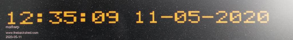 Notice how the left side of the "0" in "11-05" is wider than the right. This is a monitor sampling issue and probably wouldn't occur on an old analogue CRT monitor. The memory used is 480x432 pixels and this is arranged exactly like we saw for mode 1 earlier, top left to bottom right. Mode 3 displays 320x200 pixels. You can probably easily guess now how the 320 is created. The pixel clock is halved from 31.5MHz to 15.75MHz. As this is a simple power of 2 there is no sampling issue like we saw with mode 4. However the monitor is still expecting 480 lines and that can't be changed. Unfortunately the LTDC doesn't have the capability to clock out each line of data from memory twice so we have had to replicate each line in the firmware. The memory used is therefore only half that of 640x400 rather than a quarter. As for mode 2 frame blanking is increased by 80 lines split between the top and bottom. The memory used is 320x400 pixels and to get the address of a pixel in memory we now have to compensate for each line being duplicated. e.g. for an 8-bit colour depth: add1% =MM.INFO(page address 0)+ (y * 2) * MM.HRES + x add2% =MM.INFO(page address 0)+ (y * 2 + 1) * MM.HRES + x Mode 5 displays 240x216 pixels and I'll leave to the reader to extrapolate from modes 3 and 4 as to how this works. Supported colour depths The CMM2 supports 3 colour depths 8-bit uses 1 byte per pixel and uses RGB332. That means there are three bits coding the red intensity (8 levels), three for green (8 levels) and two for blue (4 levels). However, as we saw earlier we can change this using the MAP command and function so, for example, we could create a grey-scale map with 256 different "grey" levels. 16-bit uses 2 bytes per pixel and uses RGB565. That means there are five bits coding the red intensity (32 levels), six for green (64 levels) and five for blue (32 levels). Although this may seem limited, colour images displayed in RGB565 on a normal monitor are pretty much indistinguishable from those with greater colour depth. 12-bit uses 4 bytes per pixel and uses ARGB4444. That means there are four bits coding the red intensity (16 levels), four for green (16 levels) and four for blue (16 levels). In addition there are 4-bits that encode the transparency. i.e. the extent to which the colour masks anything underneath it. Think about paint. If you paint white on top of red you will still see a pink blush after the first coat. Although the white paint is "pure" white it allows some of the red to be seen through it. In the case of ARGB4444 the 4 "A" bits range from 15=solid to 0=totally transparent. Now, transparency isn't much use if there is nothing to be transparent over. So 12-bit mode has two layers and hence it takes 4 bytes per pixel - more on this later. In all cases the firmware translates from the colour specification you provide which is in RGB888 or for 12-bit mode ARGB8888 to the internal format for the display colour depth selected. This means the Basic code is identical irrespective of colour depth (except if you use the MAP command in 8-bit mode or are using Maximite compatibility mode) The MODE command The explanation of the mode command in the user manual is very comprehensive so there is little point in reproducing it again here. However, of particular importance is the number of video pages that are available in each mode. The firmware rounds up the amount of video memory used for any resolution/colour depth to the nearest multiple of 128Kbytes (128*1024=131072). So 320x200x8-bit seems like it should need 64000 bytes but remember each line must be duplicated so it really needs 128000 which is less than 131072. This means we can have 4 video pages in the fast internal memory (512K available) and another 24 in the 3Mbytes of SDRAM. As before MM.INFO(PAGE ADDRESS n) can give us the address of any of the pages. Page 0 is always the display page but when programming for performance there is an advantage to using a page in the faster memory for other uses. The syntax of the mode command is: MODE mode, bits [, bg [, int]] We now know all about the mode and the bits and what the firmware is doing behind the scenes to create the images. We will deal with bg which is only used in 12-bit mode later but for now we can look at the "int" parameter. int is the name of an MMBasic interrupt routine which is called immediately after the last active row of data is clocked out. This is before the actual frame-blanking pulse (actually it occurs at the beginning of the front-porch period which bizarrely is at the end of the frame whereas the back porch is at the beginning - WTF?). This is important to understand because before any new data is read from the memory the front porch period, the actual VSync frame pulse period and the back porch period will all have elapsed. In CMM2 terms this can be quite a long time. For Modes 2 and 3, there are 400 lines displayed and the complete frame has 500 line periods so there is a dead time of 2.66 milliseconds when the display can be written and no screen artifacts will ever appear. For Mode 1 this period is 0.74mSec and for modes 4 and 5 it is 1.65mSec You can actually effectively extend this period if you arrange your code to write from the top of the screen downwards. As long as your writes keep ahead of the LTDC reading the memory then there will be no artifacts or tearing. Lets build a very simple digital clock with big digits using the frame interrupt and show that there are never any screen artifacts ' set to 320x200 mode, with a frame interrupt ' NB the background colour must be specified but is ignored in this mode mode 3, 8, 0, frameint ' set a global variable that will be updated by the frame interrupt fi%=0 ' loop forever do Ā do Ā loop while fi%=0 'wait until the frame interrupt has happened ' write out the time in the middle of the screen Ā text mm.hres\2, mm.vres\2, time$, CM, 6,, RGB(red) ' prime ready for the next interrupt Āfi%=0 loop sub frameint Āfi%=1 end sub 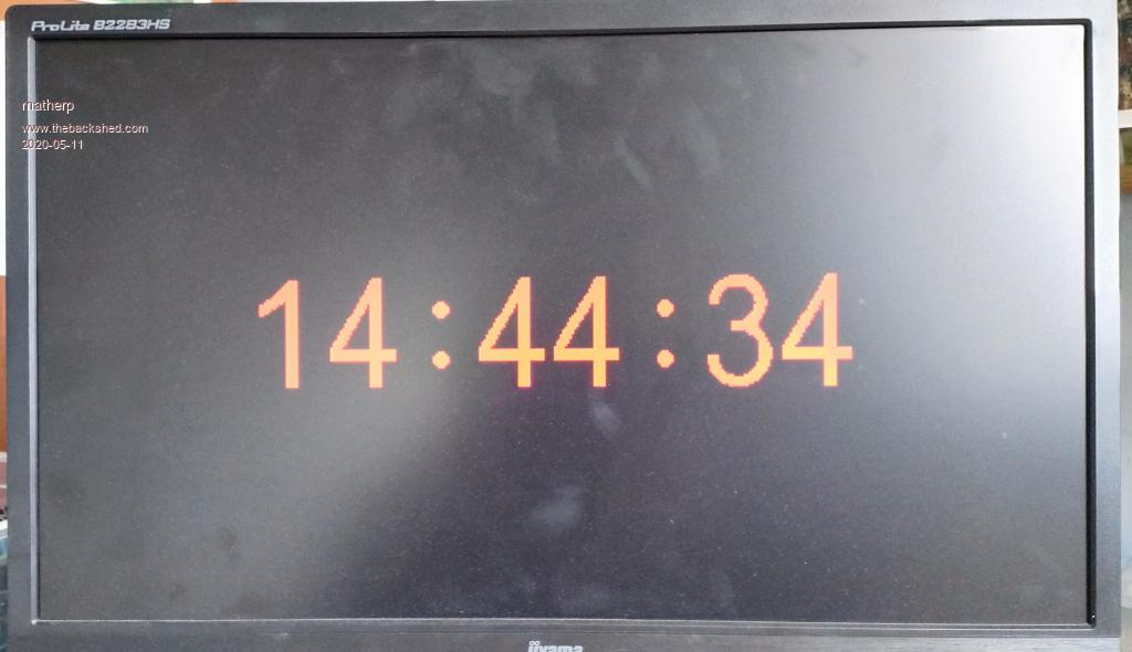 Note that I am not doing any screen updates in the interrupt routine - you wouldn't do that would you? Interrupts must always be kept short and the best approach is always to set a flag that can be processed in the main program. Edited 2020-05-12 00:11 by matherp |
||||
| matherp Guru Joined: 11/12/2012 Location: United KingdomPosts: 11698 |
The PAGE command In the second post in this thread we met the PAGE COPY command and now understand how to move information from one page to another. This can be the complete page using PAGE COPY or part of a page using BLIT. We have also investigated the PAGE WRITE command that allows us to select the page where graphics commands will write their data In this post we will look at the two other PAGE sub-commands: PAGE SCROLL and PAGE STITCH PAGE SCROLL PAGE SCROLL does what it says. It scrolls a selectable page (doesn't need to be page 0) horizontally and/or vertically by a selectable amount. In addition it allows you to control what happens to the area vacated by the action of the scroll. PAGE SCROLL pageno, x, y [,fillcolour] Some examples: LOAD JPG "bondi":DO:LOOP load a sample jpg in 800x600x16 resolution 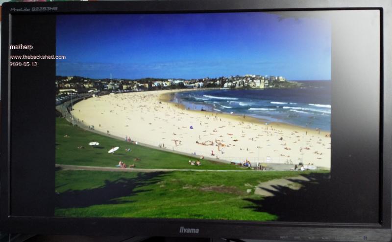 LOAD JPG "bondi":PAGE SCROLL 0, 100,100:DO:LOOP scroll the picture 100 right and 100 up, moving the scrolled off area to the now vacated part of the screen. Note that the vertical move always happens first. If you need the sideways move first you will need to use the command twice. 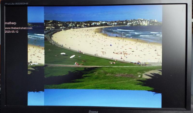 LOAD JPG "bondi":PAGE SCROLL 0, 100,100,-1:DO:LOOP scroll the picture 100 up and 100 right, leave the vacated off area as-is 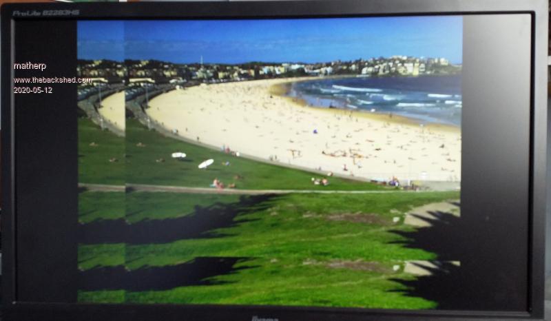 LOAD JPG "bondi":PAGE SCROLL 0, 100,100,RGB(RED):DO:LOOP scroll the picture 100 up and 100 right,replace the vacated area with a fixed colour 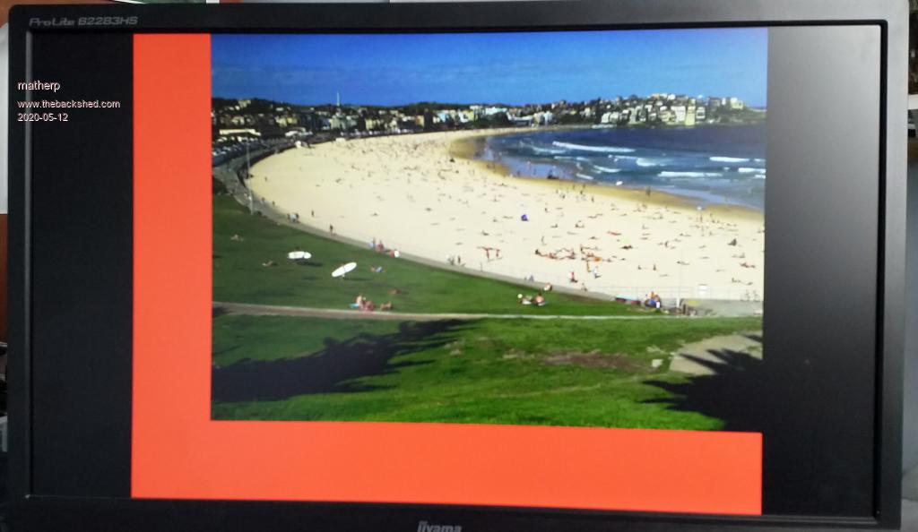 Time to load a 800x600 full colour jpg was 347 milliseconds Worst case time to scroll the image with image wrap was 125 milliseconds. All other lower resolutions or lower colour depths will be faster. Of course moving a 800x600 image with 2 bytes per pixel takes a little time but try this example program at 320x200x16 option explicit option default none dim x%(9),xd%(9) dim y%(9),yd%(9) dim integer i,c,f, xp, yp,k,t dim float s ' Work in 320x200 resolution RGB565 mode 3,16 cls 'create the coordinates of a star outline for i=0 to 9 step 2 Āx%(i)=-(SIN(rad(i*36))*20) Āy%(i)=-(COS(rad(i*36))*20) Āx%(i+1)=-(SIN(rad((i+1)*36))*7.6) Āy%(i+1)=-(COS(rad((i+1)*36))*7.6) next i 'Set to write to page 1 and clear it page write 1 cls 'create 40 random stars on page 1 using the polygon fill command do Ā Āc=rnd()*255 + ((rnd()* 255)<<8) + ((rnd()* 255)<<16) Āf=rnd()*255 + ((rnd()* 255)<<8) + ((rnd()* 255)<<16) Āxp=rnd()*mm.hres Āyp=rnd()*mm.vres Ās=rnd() Āt=0 Āfor i=0 to 9 Ā Āxd%(i)=x%(i)*s+xp Ā Āyd%(i)=y%(i)*s+yp Ā Āif xd%(i)<0 or yd%(i)<0 or xd%(i)>=MM.Hres or yd%(i)>=MM.Vres then t=1 Ānext i Āif t=0 then Ā Āpolygon xd%(), yd%(), c, f Ā Āk=k+1 Āendif loop until k=40 k=0 ' 'Now lets see how fast scroll really is do Āpage copy 1 to 0,d 'copy page 1 to page 0 during frame blanking Āpage scroll 1,2,1 'scroll page 1 immediately after loop For many simple early games they used a seamless background that was a single image that could be scrolled horizontally, vertically, or even both with no obvious join Try the attached with load jpg "seamless":do: page scroll 0,1,1:loop seamless.zip Now you should be able to see how to create a slideshow with one picture smoothly replacing another from the right. I'll provide some pseudo code for you to complete and try for yourself. load an image to page 1 load an image to page 2 loop Ā Ācopy page 1 to page 0 during frame blanking Ā Āscroll page 1 left by a "n" pixels Ā ĀBLIT n pixels from the left of page 2 to the right of page 1 Ā Āscroll page 2 left by "n" pixels Ā ĀIf you have just used all of page 2 then load the next image to page 2 end loop PAGE STITCH PAGE STITCH is really only a short form way of doing what was proposed above with scroll and BLIT PAGE STITCH frompage1, frompage_2, topage, offset This says we are going to take columns from the right side of frompage1 and columns from the left side of frompage2 and copy them to topage as a single action. The offset parameter determines how many columns are going to be taken from frompage2 - perhaps the offset parameter was badly named? This single command makes it very easy to create a horizontally scrolling background across a number of separate images. This video shows how fast this can take place The example code presented below slows this down by syncing everything up with frame blanking to get a very smoothly moving image. As the monitor frame rate is 75Hz and the scroll is happening 2 pixels at a time the movement is limited to 150 pixels per second. Remove the ",b" parameter in the page copies to see things at maximum speed. ' test stitch ' Run at 320x200x16 bit mode mode 3,16 'clear the first 7 video pages For i= 0 to 6: page write i:cls:next i 'now write each part of the background image to a separate page ' doing this at the beginning ensures the program won't stall waiting for images to be loaded page write 2 load png "part01",,,15 page write 3 load png "part02",,,15 page write 4 load png "part03",,,15 page write 5 load png "part04",,,15 ' Main program loop do 'merge pages 2 and 3 stepping 2 pixels at a time Āfor i=0 to MM.Hres step 2 Ā Āpage stitch 2,3,6,i Ā Āpage copy 6 to 0,b Ānext i ' now page 2 is used up so merge pages 3 and 4 Āfor i=2 to MM.Hres step 2 Ā Āpage stitch 3,4,6,i Ā Āpage copy 6 to 0,b Ānext i ' finally merge pages 4 and 5 Āfor i=2 to MM.Hres step 2 Ā Āpage stitch 4,5,6,i Ā Āpage copy 6 to 0,b Ānext i 'we are now at the rightmost side of the composite image so we can start moving back left Āfor i= MM.Hres to 0 step -2 Ā Āpage stitch 4,5,6,i Ā Āpage copy 6 to 0,b Ānext i Āfor i= MM.Hres-2 to 0 step -2 Ā Āpage stitch 3,4,6,i Ā Āpage copy 6 to 0,b Ānext i Āfor i= MM.Hres-2 to 0 step -2 Ā Āpage stitch 2,3,6,i Ā Āpage copy 6 to 0,b Ānext i ' Once all the way left then start again loop Here are the images used in this demo Parts.zip Hopefully you can see from this short post that it is very easy to create and manipulate moving images on the screen. Of course, this needn't be anything to do with games. Scrolling graphs etc. are just as easy. Edited 2020-05-13 01:46 by matherp |
||||
| matherp Guru Joined: 11/12/2012 Location: United KingdomPosts: 11698 |
12-bit Modes The 12-bit graphics modes are one of the most powerful capabilities of the Colour Maximite 2. They enable us to create semi-transparent objects floating over a background like the ghost demo or the effect of parallax like the stars demo. ĀNote in the latter how the nearer stars are moving faster relative to the spaceship than those further away. The way that it works is using layers. The concept will be very familiar to those of you doing manipulations of images with any of the more capable graphics packages. In 12-bit colour mode the CMM2 supports three layers. This is a property of the processor chip itself. The bottom layer is just a single colour background and to set the colour we specify it in the MODE command. MODE 3,12,RGB(blue) Will put a blue over the screen. Note how, as we are at the command prompt, the status line and command prompt overwrite the background, but it shows through the unset pixels in each character. To change the background colour you can just use the mode command again with the new colour. Other information on the screen won't be affected (NB: V5.05.02RC26 or greater) 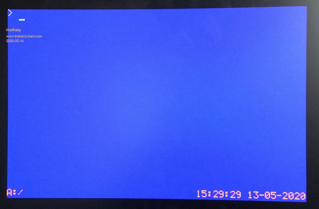 The status line and command prompt are writing to the second layer of the three layers and the data for this layer is stored in page 0 The data for the third and top layer is stored in page 1. Unless pixels are set to have some transparency (more on this later) any information written to layer 3 (page 1) will block out layers 1 and 2. We can prove this. Type: PAGE WRITE 1: TEXT 247,190,"X":page write 0 We have to do the command as a single line to avoid the status updating while we are writing to page 1 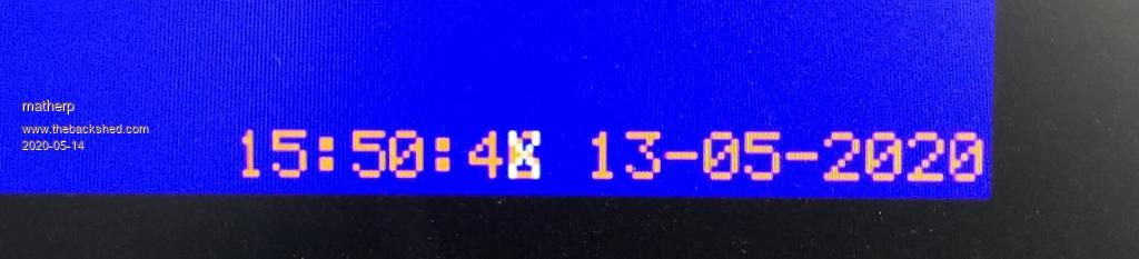 Note how the "X" appears to have overwritten the brown seconds units but the seconds are still incrementing underneath and pixels that are not covered by the "X" show normally Now type: PAGE WRITE 1: TEXT 247,190," ":page write 0 The "X" disappears and the seconds continue incrementing normally. Black, i.e. the pixels in text that aren't set, defaults to being a completely transparent colour. Now type CLS RGB(black,15) 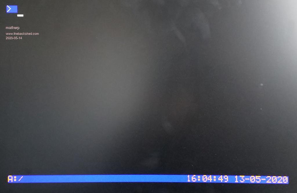 Check out the RGB function in the user manual. We have asked the system to clear the screen but to use a non-transparent black. Valid transparency values are from 0 to 15 where 15 is a solid colour. However, the default background colour is fully transparent black so the characters associated with the command prompt and the status line still show the blue colour. Now try: COLOUR RGB(WHITE), RGB(BLACK,15) We have set the background colour to solid black rather than transparent black and now the blue colour on layer 1 has gone completely (NB: V5.05.02RC26 or greater). Lets play a bit more with transparency 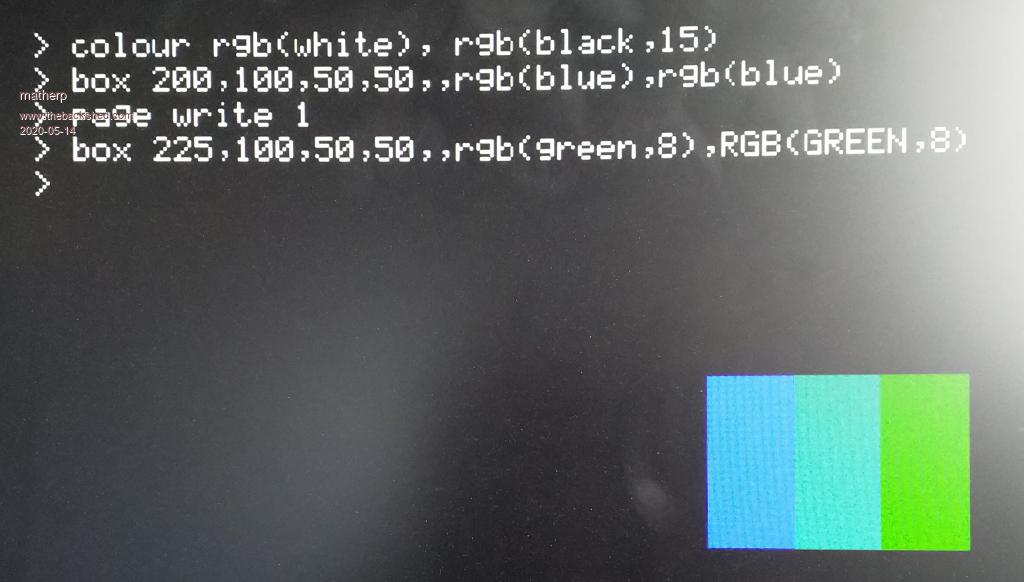 The blue square on layer 2 (PAGE 0) is partially overwritten by the green square on layer 3 (PAGE 1) which is set to 50% transparency. Where the squares overlap we get CYAN We could do the same thing with layer 2 and the background layer 1 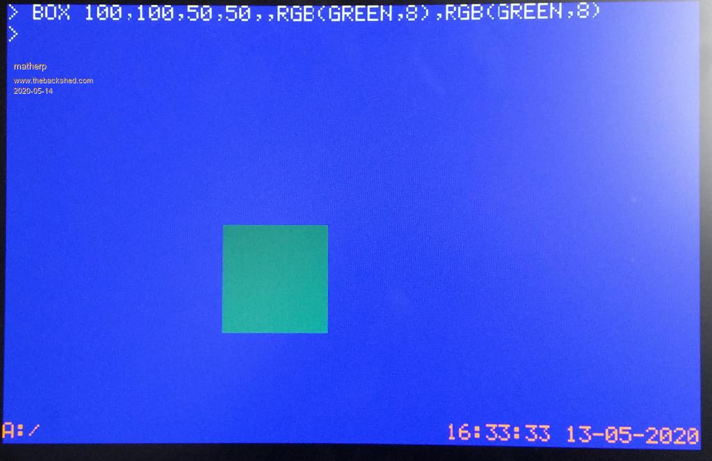 That should give you a good understanding of 12-bit mode (ARGB4444) and how the "A" transparency can be used to create interesting effects. The most important thing to note is that in 12-bit mode the CMM2 is displaying information from two pages at the same time (PAGE 0 and PAGE 1) plus a fixed background colour. Information on PAGE 0 will overwrite the background depending on the transparency of each individual pixel on PAGE 0. A transparency of 0 will have no effect. A transparency of 15 is a solid colour and will overwrite completely. Information on PAGE 1 will overwrite both the background and PAGE 0 depending on the transparency of each individual pixel. We will revisit this with a more interesting example when we look at sprites. However, the next post will look in more detail at loading and manipulating pictures Edited 2020-05-14 04:57 by matherp |
||||
| matherp Guru Joined: 11/12/2012 Location: United KingdomPosts: 11698 |
Images In this post we will look at the pros and cons of the image formats supported by the CMM2: jpg, gif, png, and bmp We will start by putting the CMM2 into MODE 2,16 i.e. 640x400 RGB565 and for testing purposes I have saved the same image in all 4 formats 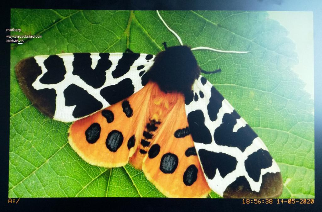 File sizes are as follows > list files "caja.*" A:/ 18:50 14-05-2020 Ā Ā 768054 Ācaja.bmp 18:50 14-05-2020 Ā Ā 217064 Ācaja.gif 18:49 14-05-2020 Ā Ā 233823 Ācaja.jpg 18:51 14-05-2020 Ā Ā 506373 Ācaja.png 0 directories, 4 files > And times to load in milliseconds > mode 2,16 > timer=0:load bmp "caja":?timer 541.699 > timer=0:load gif "caja":?timer 728.09 > timer=0:load jpg "caja":?timer 216.345 > timer=0:load png "caja":?timer 509.873 So JPGs are small and load much faster than anything else. The reasons for this are twofold; first there is less data to read from the SDcard, second the STM32H743 includes a hardware jpg decoder so the CPU isn't used. So we use jpgs for everything? perhaps not..... There are two main downsides with the jpg format on the CMM2: 1. jpgs do not support transparency 2. jpgs cannot be bigger than the current display resolution. If we tried to load a 800x600 jpg while in MODE 2 we would get an error. This is because the hardware decoder uses information from the way we have set up the page in LTDC to determine how to decode the image. We would also get an error even with a 640x400 jpg if we tried to load it with an x,y offset other than 0 LOAD JPG file$ [, x, y] One third limitation of the jpg support on the CMM2 is that it does not support progressive encoding. This is a technique that was developed for web use where a picture would appear fast but with low resolution and then the detail would "progressively" appear. This limitation is easily overcome by using any decent graphics program on your computer to save the image normally. What about png files? The only format to support transparency so the only choice in some applications Reasonably fast to load but: 1. Decoding png files eats memory. Even with 5MB available we cannot decode a 800x600 image so 640x400 is the biggest that can be practically supported 2. png cannot be bigger than the current display resolution. If we tried to load a 640x400 jpg while in MODE 3 we would get an error. We would also get an error even with a 320x200 png in mode 3 if we tried to load it with an x,y offset other than 0 3. The CMM2 only supports RGB888 and ARGB8888 formats - files are comparatively large Next up gif files The only format to support animations GIF files can be bigger than the screen format or overlap the screen edge GIF files are small but: 1. slow 2. Only 256 colours used out of the palette of 65536 Finally bmp files The safe option BMP files image can be bigger than the screen format or overlap the screen edge SAVE IMAGE saves BMP files No practical limit on the image size, but of course only part of a very large image can be displayed. but: full-colour BMP files are 3 bytes per pixel + header i.e. large A BMP image loads a line at a time from the bottom up which may not be what you want I'll add to this post tomorrow and look at IMAGE RESIZE and IMAGE ROTATE Edited 2020-05-15 05:05 by matherp |
||||
| matherp Guru Joined: 11/12/2012 Location: United KingdomPosts: 11698 |
I'll just finish off the previous post as promised IMAGE RESIZE and IMAGE ROTATE use some fairly complex math to scale and rotate images. They are therefore comparatively slow compared to actions like page copies but useful nevertheless. An example of rotation is available here. In fact this was done on an early release of the code and various enhancements have speeded it up somewhat since then. As an example of their use lets take an 800x600 image that is in landscape and scale and rotate it to a 600x450 image in portrait. This then gives us the worst case timings for the two functions - biggest image, highest colour depth. tigerside800.zip 'Set to 800x600 16 bit mode ' NB to use this mode it must be unlocked first with OPTION MODES UNLOCKED mode 1,16 'set output to page 1 page write 1 ' lets see how long it all takes timer=0 'load our 800x600 image to page 1 load jpg "tigerside800" page write 0 print @(0,0)"Time to load JPG" print timer/1000, "seconds" timer=0 page write 1 'When we rotate the image it can't be more than 600 pixels high so resize it 'Check the manual for syntax but we are specifying to resize it and place the resized image centrally over the old image image resize 0,0,800,600,100,75,600,450 page write 0 print "Time to resize" print timer/1000, "seconds" timer=0 page write 1 'Now we need to rotate the image 'In the case of the example this is a rotation of 270 degrees clockwise to get it the correct way up ' Note that the rotated image has to fit into a new area no bigger than the area to be rotated 'So we need to rotate a square area as big as the biggest dimension we need in the result image rotate 100,0,600,600,100,0,270 page write 0 print "Time to rotate" print timer/1000, "seconds" timer=0 'Now we can go back to page 0 page write 0 ' Copy the part of page 1 containing the rotated image to page 0 using BLIT blit 175,0,175,0,450,600,1 print "Time to copy" print timer/1000, "seconds" do loop 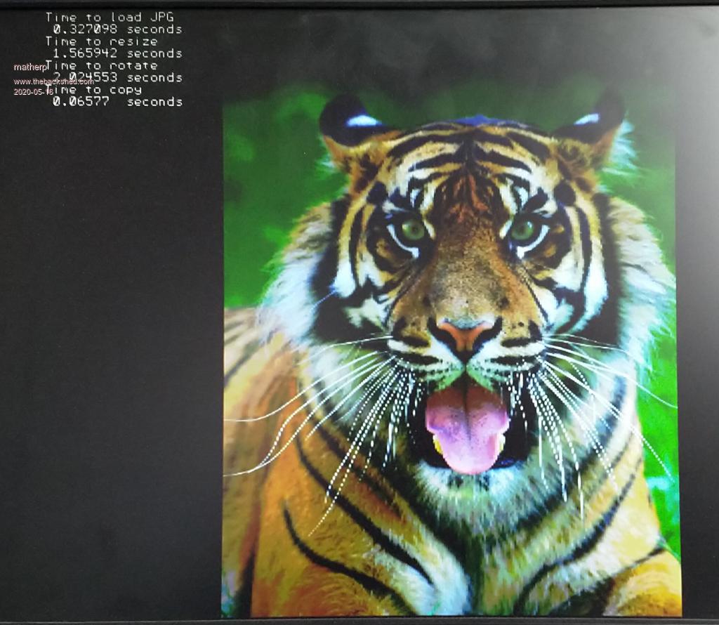 One important thing to note is that resizing and rotating by definition lose some information and accuracy. For this reason if you want to do something like the rotating image in the video you should do each rotation from the original rather than incrementally rotating the previous result otherwise the image will quickly degenerate. Next post we start on sprites by learning what is a sprite and the various ways to create them Edited 2020-05-16 22:12 by matherp |
||||
| matherp Guru Joined: 11/12/2012 Location: United KingdomPosts: 11698 |
Sprites and how to create them Sprites are somewhat complex and in any case they are just something reserved for games programmers. Wrong on both counts as we will see. The concept of a sprite is simple. It is an image stored in the computer memory. It can be written to the screen like any other image. However, what makes a sprite special is that any decent implementation of sprites will have the capability of storing what is on the screen in the area that the sprite will be displayed and this happens automatically without additional code from the user of the sprite. What this means is that it is possible to write code that displays a sprite and then remove it and the display will be restored exactly like it was before. Perhaps more usefully you can display a sprite and then repeatedly move it on the screen and with each move the original screen image will be restored to create the illusion of the sprite moving across and in front of the original screen image. We will show simple examples of this later in the next post. Before proceeding to load some sprites it is important to understand how sprites are stored in the CMM2 memory. Each sprite when created has two areas of memory allocated to it. Both are the size needed to store a bounding rectangle with width and height equal to the maximum dimensions of the sprite. One of the memory areas holds the sprite image itself. The other is an empty slot ready to hold the image that was on the screen when the sprite is displayed. In both cases the number of bytes is also dependent on the current colour depth of the video mode in use - either one or two bytes per pixel. The CMM2 supports up to 64 sprites numbered 1 to 64 and the number is used whenever we want to refer to a particular sprite. Setting up constants at the top of a program would be a good way to make your code more readable when using sprites Now we know what a sprite is we need to know how to create one. On the CMM2 there are four methods of creating a sprite 1. Load a sprite from an ascii file in the same way as was done on the original Colour Maximite 2. Load a sprite from a PNG (Portable Network Graphics) format file 3. Create a sprite by reading from what is already displayed on one of the CMM2 video pages 4. Copy an existing sprite to create a new one. We will look at each of these in turn: Load a sprite from an ascii file The CMM2 supports creating sprites by reading in an ascii file formatted as described in the Colour Maximite manual with a key enhancement: CMM2 sprites can be any width and any height. Sprites are loaded from Maximite style SPRITE files using SPRITE LOAD filename$. There is now has an optional parameter available in the first line of the sprite file. The definition of the new first line is Horizontal size in pixels(need not be 16), No. of sprites described in the file, Vertical of sprites in pixels (need not be 16) If the Vertical size parameter is omitted then the first parameter is used for both width and height allowing complete compatibility with CMM sprite files e.g. a red mouse pointer 13 pixels wide and 19 high 13,1,19 4 44 4 4 4 Ā4 4 Ā 4 4 Ā Ā4 4 Ā Ā 4 4 Ā Ā Ā4 4 Ā Ā Ā 4 4 Ā Ā Ā Ā4 4 Ā Ā Ā Ā 4 4 Ā Ā Ā Ā Ā4 4 Ā Ā Ā444444 4 Ā 4 Ā4 4 Ā44 Ā4 4 4 Ā4 Ā4 44 Ā 4 Ā4 Ā Ā 4 Ā4 Ā Ā 4444 To create the sprites described by the file we use the command: SPRITE LOAD fname [,start_sprite_number] SPRITE LOAD loads CMM1 style sprite files. You can load multiple CMM1 style sprite files by specifying the start sprite number of each file making sure they donÆt overlap. The start sprite number defaults to 1 if not specified. To try this method, save the above as "mouse.spr" Then: SPRITE LOAD "mouse.spr",5 SPRITE SHOW 5,100,100,1 Note CMM style sprite files are limited to the 8 CMM colours and use the CMM colour coding. Ignore for the moment the specifics of the SPRITE SHOW command , we will get to that later. Load a sprite from a png file This method can be slightly more complex but is much more powerful not least because the images can be full colour. If you google "png transparent" and look at the images found you will see lots that look like this:  Note that surrounding the butterfly there appears to be a chequerboard pattern. This identifies areas in the image where there is nothing there. This is different from the butterfly appearing on a black or white background. In this case the background is non-existent or see-through. PNG files that look like this will have been written in ARGB8888 format and these files are ideal for creating sprites. The format of the command for creating a sprite from a PNG file is: SPRITE LOADPNG spriteno, fname$ [, transparency_cut_off] The first two parameters are obvious, the number of the sprite we are creating and the name of the png file we will be reading from. The last transparency_cut_off parameter is optional and defaults to 8. It determines how the A level in ARGB8888 will be treated. In the png file A can be a value between 0 and 255 but to keep things simple the CMM2 will treat each pixel as being fully transparent or fully solid. The CMM2 firmware divides the A value in the png file by 16 and then compares it with the transparency_cut_off. If it is greater or equal to transparency_cut_off the pixel will be a solid colour. If it is less it will be completely transparent. This distinction is important as it allows us to have both transparent pixels and solid BLACK pixels. i.e we don't have to specify a particular colour to be "transparent" In the next post we will use sprites read in from png files in the examples but we for now we know how to load them. Create a sprite by reading from what is already displayed on one of the CMM2 video pages This can be the simplest way of creating a sprite. We simply specify that we want to read what is on one of the video pages and create a sprite from it Given that, the syntax is obvious: SPRITE READ [#]n, x , y, w, h This says create sprite number n by reading what is on the screen in the rectangle with top left coordinate x,y and width w and height h. ĀThere is just one added component to this: SPRITE READ will read from the PAGE currently specified by PAGE WRITE. This allows us to read in sprites without changing PAGE 0 which is always being displayed. Suppose we want a sprite which is simply a red box 10x10 pixels PAGE WRITE 1 CLS RGB(RED) SPRITE READ 1, 0, 0, 10, 10 PAGE WRITE 0 SPRITE SHOW 1,100,100,1 would do the job and display the sprite on the display without having to see its creation. Note ĀBLIT READ and SPRITE READ are identical and do exactly the same thing. Copy an existing sprite to create a new one As mentioned earlier, each sprite created uses two RAM buffers one for the sprite and one to store the display contents when the sprite is shown. This can use quite a lot of memory for big sprites. However, if we want many sprites that are based on the same image ( the blocks in this demo are all sprites) we can copy one sprite to many others and the "children" sprites will only take the one memory buffer needed to save the screen but share the image with the "parent" The syntax for copying sprites is: SPRITE COPY [#]n, [#]m, nbr This makes a copy of sprite ōnö to ōnbrö of new sprites starting a number ōmö. The code from the demo uses both this and SPRITE READ to create the block sprites ' Draw one box of each colour Box 401,1,18,48,2,RGB(green),RGB(Magenta) Box 421,1,18,48,2,RGB(red),RGB(cyan) Box 441,1,18,48,2,RGB(yellow),RGB(blue) Box 461,1,18,48,2,RGB(white),RGB(red) Box 481,1,18,48,2,RGB(Magenta),RGB(GREEN) ' read in each block as a parent sprite SPRITE read 10+i,401,1,18,48 SPRITE read 18+i,421,1,18,48 SPRITE read 26+i,441,1,18,48 SPRITE read 34+i,461,1,18,48 SPRITE read 42+i,481,1,18,48 'copy each parent to 7 children SPRITE copy 10,11,7 SPRITE copy 18,19,7 SPRITE copy 26,27,7 SPRITE copy 34,35,7 SPRITE copy 42,43,7 We now know how to create sprites and can think about the pros and cons of the various methods. Next post we had better start looking at how to use them Edited 2020-05-17 05:11 by matherp |
||||
| matherp Guru Joined: 11/12/2012 Location: United KingdomPosts: 11698 |
Sorry about the delay in getting to this post - people keep finding bugs that need fixing  In this post I will look at some of the Basics of sprites and then the final sprite post will look at collisions. I might then do one more post on 3D graphics and try to de-mystify some of the maths behind them. In the previous post we saw what a sprite is and how to create one so we can start here by getting rid of one or more sprites. This may be important to free up the 64 sprite slots for new sprites and the syntax is obvious Executing these commands frees up the sprite slot and the memory used by the sprite. There is one important difference in their usage. Closing an individual sprite will also remove it from the screen if it is visible. Closing all sprites leaves the screen untouched as this is likely only to be used at the end of a program or when switching to a completely new context in a game. It is also important to note that you can't close a sprite from which copies have been made until all of the copies have been closed. So we can create sprites and destroy them but we now need to know how to use them. There is one overriding rule to be followed to make things work: While sprites are in use all sprite commands must be done with the same PAGE WRITE set This need not be PAGE 0, the display page, but must be consistent for all SPRITE commands. You can move to other pages and use other graphics commands but if any sprite is active then all subsequent sprite commands must be to that page. To keep things simple for the moment we will not change the page we are writing to and leave it at PAGE 0. I've attached the sprite file for the red mouse pointer we saw earlier and an image to use in the next example. NB: you need at least V5.05.02RC39 to run this example due to a bug in earlier versions mouse.zip 'set to 320x200 16 bit colour mode 3,16 ' load the mouse cursor as sprite number 1 sprite load "mouse.spr",1 'load a background image load bmp "tiger320" 'set up some variables to track the sprite position and show it dim integer x=mm.hres/2, y=mm.vres/2 sprite show 1, x, y, 1 'loop forever do 'use the keydown function with the USB keyboard to check for a keypress 'you can change this to use inkey$ to use a serial console if keydown(0) then 'There is a key pressed so check for one of the arrow keys if keydown(1)=128 then y=y-1 if keydown(1)=129 then y=y+1 if keydown(1)=130 then x=x-1 if keydown(1)=131 then x=x+1 ' use the sprite function to check if the sprite needs to move ' by comparing its actual position to the new x,y position ' if it is different then display the sprite in the new position ' this will automatically restore the background overwritten by the original sprite ' and then rewrite it in the new position if x<> sprite(x,1) or y <> sprite(y,1) then sprite show 1, x, y, 1 endif pause 10 loop 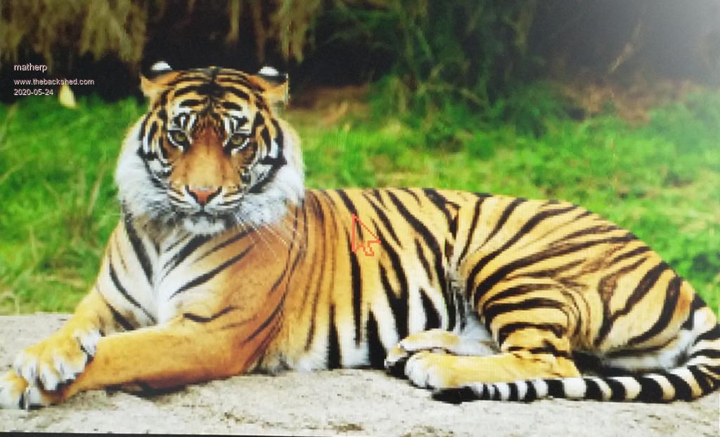 Try keeping the left arrow pressed and watch as the sprite leaves the screen [12] Error: -13 is invalid (valid is -12 to 319) Oops: sprites must have at least one pixel of their containing rectangle on the screen otherwise you will get an error. We can easily check for this in the code if keydown(1)=128 and sprite(y,1) + sprite(h,1) > 1 then y=y-1 if keydown(1)=129 and sprite(y,1)+1 < MM.VRES then y=y+1 if keydown(1)=130 and sprite(x,1) + sprite(w,1) > 1 then x=x-1 if keydown(1)=131 and sprite(x,1)+1 < MM.HRES then x=x+1 The SPRITE function is very useful for telling us about the sprite. Check the manual for all the various SPRITE function parameters. The important command we have used here is SPRITE SHOW. This command is used both to display a sprite and to move it. However it has two additional parameters that we haven't yet considered. SPRITE SHOW [#n], x, y, layer [,orientation] The optional orientation parameter acts to modify the sprite as it is displayed in the same way as we saw for the BLIT command, 0=normal, 1=mirrored left to right, 2=mirrored top to bottom, 3=rotated 180 degrees. The mandatory (collision) layer parameter does two things for us relating to collisions and movement and can be set between 0 and 10. Sprites shown on layer 0 will move with the background if we use SPRITE SCROLL or SPRITE SCROLLR. Sprites on all other layers will remain fixed on the screen during a scroll and the background will move underneath them Sprites collisions are detected when a sprite overlaps another sprite on the same layer or layer 0 so collisions can be caused by moving a sprite on any layer or scrolling the background such that a layer 0 sprite now overlaps a sprite on any of the other layers. Collisions will be discussed in much more detail in the next post but there are other sprite commands we should look at first. SPRITE WRITE and BLIT WRITE do exactly the same thing. In both case the SPRITE is written out but the background image isn't stored first and you can WRITE the same sprite as many times as you wish to different locations on the screen. In essence the command is just using the sprite as a in memory image that can be used whenever required. SPRITE HIDE does what it says, it removes a sprite from the screen and restores the background we can add this to our example program and make the cursor flash SPRITE NEXT and SPRITE MOVE commands allow you to create a sequence of sprite actions which will be executed as a single atomic transaction. This was developed for other platforms to avoid tearing and flashing effects but because on the CMM2 sprites can be moved on non-visible pages these commands are not as important. The SPRITE SCROLL and SPRITE SCROLLR commands allow you to move the background image under the sprites for the whole screen or just part of it. SPRITE SCROLL is really identical to PAGE SCROLL that we discussed in detail above with the simple exception that all sprites on layers 1 to 10 are automatically hidden before the scroll and then replaced in their original positions afterwards. SPRITE SCROLLR does exactly the same thing but allows you to specify a part of the background image to scroll The last sprite command we will consider in this post is SPRITE TRANSPARENCY and this is used to create the ghost demo The full code for this is attached and explained below. This uses many of the concepts we have seen in the posts on this thread and brings them together. What I hope will be clear from reading the code is how easy it is to create stunning effects with the CMM2 once you understand a little about the graphics are designed and work. Image files 2020-05-08_234454_Ghost.zip 'set to 640x400 mode with 2 video layers and 12-bit colour. Page 0 is the bottom layer and page 1 is the top mode 2,12 'clear the first three framebuffers (pages) for i=0 to 2:page write i:cls:next i 'load a sprite which is the image of the ghost from a png file. 'The fact it is a png is important as png files encode transparency as well as solid colours sprite loadpng 1,"ghost" 'set that we are going to write to the background layer page write 0 'load the background image to the background layer - page 0 load png "part02" 'The image I am using is only 320x200 so I'm going to resize it to fit the screen image resize 0,0,320,200,0,0,640,400 'initialise the display position of the ghost x=100 y=50 'initialise the transparency of the ghost ' transparencies go from 1 (nearly invisible) to 15 (solid colour) t=8 'set to write to page 2 which is not being displayed page write 2 ' output the ghost on page 2 sprite show 1,x,y,1 i=0 'start the main process loop do 'do some silly maths to create a random walk of the ghost in both position and ' transparency while keeping it within the display bounds and the transparency ' within useful limits i=i+1 if i mod 5 = 0 then c=rnd()-0.5 if i mod 3 = 0 then a=rnd()*8-4 if i mod 3 = 0 then b=rnd()*6-3 x=x+a if x<0 then x=0 if x>MM.HRES-sprite(w,1) then x=mm.hres-sprite(w,1) y=y+b if y<0 then y=0 if y>MM.VRES-sprite(h,1) then y=mm.vres-sprite(h,1) t=t+c if t<3 then t=3 if t>12 then t=12 'display the sprite in the new position and with the new transparency sprite transparency 1,t sprite show 1,x,y,1 'now copy page 2 to the foreground layer during frame blanking 'this ensures that there are no tearing effects in the image page copy 2 to 1,b 'slow things down a bit, the CMM2 is too fast pause 100 loop |
||||
| vegipete Guru Joined: 29/01/2013 Location: CanadaPosts: 1182 |
Here is a variation of the colour wheel example given in lesson 3 above. In this example, the wheel rotates 6 degrees at each step, giving smoother motion. This is accomplished by making the pie chart with 60 segments instead of the 6 in the original example. Each segment has its own colour number, however, groups of 10 different colours have the same actual colour values. This way, 10 adjacent segments of the pie chart have the same colour and appear to be a single piece. Animation happens the same as before, except now only a single 6 degree segment of each region changes to the next colour at each step. This example also shows some interesting Moire artefacts that appear when many slightly different angled lines meet at a point. Press CTRL-C to end the program after you have been hypnotized. Type the command "map reset" to fix colours back to normal, or you may seem some strange colours when editing or using the file manager. ' Set up an array to hold the colour mappings we are going to use Dim integer cmap(60) 'Clear the screen CLS 'Set up 6 colours in the array for i = 1 to 10 cmap( 0+i)=RGB(red) cmap(10+i)=RGB(green) cmap(20+i)=RGB(blue) cmap(30+i)=RGB(yellow) cmap(40+i)=RGB(magenta) cmap(50+i)=RGB(cyan) next i ' Do an initial update of the CLUT to set up our colours mapclut 'Display an outer circle in white Circle MM.HRes/2,MM.VRes/2,MM.VRes/2-1,0,,RGB(white),RGB(white) ' Now draw a simple colour pie chart using our new colours with the ARC command for i = 0 to 59 Arc MM.HRes/2,MM.VRes/2,0,MM.VRes/2-10,i*6,(i+1)*6,map(i+1) next i ' Start a never ending loop Do 'each time round the loop move the colours in our array one place to the left ' Use array element 0 to store the first element that is going to be at the end for i = 1 to 60 cmap(i-1)=cmap(i) next i cmap(60)=cmap(0) ' update the colour map mapclut ' pause so we can see the change Pause 25 Loop 'This subroutine updates the colour map for the colours we are using ' set map positions 1 to 60 to the new colours ' then apply the change Sub mapclut local i for i = 1 to 60 map(i)=cmap(i) next i map set End Sub Visit Vegipete's *Mite Library for cool programs. |
||||
| panky Guru Joined: 02/10/2012 Location: AustraliaPosts: 1132 |
Peter, Solely for my own use, I have stitched together your excellent series above into a word document using LibreOffice Writer (.odt format). I have not converted the screen shots that are pictures into actual screen images yet but plan to do so, again, purely for my own use. If this would be of any value to you, let me know how I may send it to you. Regards, Doug. ... almost all of the Maximites, the MicromMites, the MM Extremes, the ArmMites, the PicoMite and loving it! |
||||
| matherp Guru Joined: 11/12/2012 Location: United KingdomPosts: 11698 |
Have you removed my typos?  I really must get down to finishing the series of notes and will do it when motivation strikes. If you think the posts are generally useful then please do post a zipped odt or a PDF. Once it is finished it can go on the "fruits of the shed" and I'm sure Geoff would also include it a a document in one of the downloads |
||||
| panky Guru Joined: 02/10/2012 Location: AustraliaPosts: 1132 |
With a huge thanks to Peter for his contribution to the graphics side of the CMM2 and his kind permission to post the content of his thread on graphics, attached is the first draft of Graphics Programming on the CMM2.pdf. If you spot any errors or typos, please let me know. Peter has indicated that he has some more to add once the furor of the CMM2 release subsides a little so I will add those (or anything anyone feels is important) to any future updates. Doug. ... almost all of the Maximites, the MicromMites, the MM Extremes, the ArmMites, the PicoMite and loving it! |
||||
| Geoffg Guru Joined: 06/06/2011 Location: AustraliaPosts: 3364 |
Well done Doug. When you have finished I would like to include your PDF in the official firmware download. Geoff Graham - http://geoffg.net |
||||
| GregZone Senior Member Joined: 22/05/2020 Location: New ZealandPosts: 114 |
Nice work Doug. But it appears that all the embedded links are not working (they just appear as underlined blue text in the PDF). eg. The video links and .zip code references. So there's no way to locate these file / URL references. I don't think it's me, as I tried viewing the PDF in my browser, as well as using Adobe Reader. |
||||
| panky Guru Joined: 02/10/2012 Location: AustraliaPosts: 1132 |
Sorry folks, flakey PDF creation with PDF Creator. I tested this version, Graphics Programming on the CMM2-v1.0b.pdf on Firefox and Acrobat 9. Please let me know if there is still an issue. Also corrected a few of (my) typos. ... almost all of the Maximites, the MicromMites, the MM Extremes, the ArmMites, the PicoMite and loving it! |
||||
| panky Guru Joined: 02/10/2012 Location: AustraliaPosts: 1132 |
Thanks Geoff, it is all Peter's hard work, I just did the Word Processing slog to stitch it together into a single document. ... almost all of the Maximites, the MicromMites, the MM Extremes, the ArmMites, the PicoMite and loving it! |
||||
| Page 1 of 2 |
|||||
| The Back Shed's forum code is written, and hosted, in Australia. | © JAQ Software 2026 |
