
|
|
Forum Index : Microcontroller and PC projects : Colour Maximite Case/Box (How to ?)
| Page 1 of 2 |
|||||
| Author | Message | ||||
| Poppy Guru Joined: 25/07/2019 Location: GermanyPosts: 486 |
Hi all, how do you drill and cut out all openings on front and back, what tools do you exactly use? Any special hints? Some of you seem to get it very tidily done.  Andre ... such a GURU? Andre ... such a GURU? | ||||
| matherp Guru Joined: 11/12/2012 Location: United KingdomPosts: 11074 |
I use either a CNC router with a 1.5mm endmill or I cut them with a laser diode I have fitted to the router. I could scale this up and make them available to WW to sell but volumes would be fairly low. I can cut the supplied end plates or cut from scratch using 2mm plastiboard The ones pictured are laser cut 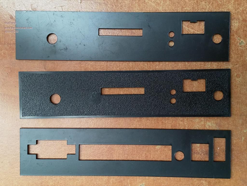 Edited 2020-05-22 17:01 by matherp |
||||
| Poppy Guru Joined: 25/07/2019 Location: GermanyPosts: 486 |
You lucky one  I wish I had a CNC, too.  The cut-outs do really look quite sharp! Any MMBASIC-Pogs out yet for CNC-Mills?  Good idea How much would it be? Andre ... such a GURU? | ||||
| Bill7300 Senior Member Joined: 05/08/2014 Location: AustraliaPosts: 159 |
Bill |
||||
| CaptainBoing Guru Joined: 07/09/2016 Location: United KingdomPosts: 2171 |
very clean results. Questions: Blue laser? Watt(LOL) power rating? cheers |
||||
| matherp Guru Joined: 11/12/2012 Location: United KingdomPosts: 11074 |
Build one, that's what I did The laser head uses a NDB7A75 diode that I'm running at 2.8A which gives me about 4W of actual laser power. Note the air assist pump in the picture. This is critical to remove fumes and burned material from the cutting site. Getting this all set up and working took many hours including designing and building the constant current source for the laser and integrating control of it into the CAM software. You can buy complete units but need to understand the power ratings. By "commercial" standards my laser is roughly 2.6A * forward voltage c5.5V = 15W but the burning power is only 4W. To cut this plastic I use 3 passes at 200mm/min. Fume extraction is essential as some plastics give off HCN when vaporized in this way - BAD 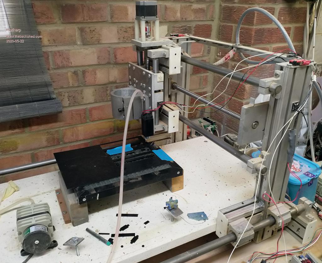 |
||||
| Poppy Guru Joined: 25/07/2019 Location: GermanyPosts: 486 |
Sure, or wouldn�t you feel blue yourself instead not having become a jedi light saber?!  Damned, looking great! Now, I wish I had the time and place to do so! Andre ... such a GURU? | ||||
| CaptainBoing Guru Joined: 07/09/2016 Location: United KingdomPosts: 2171 |
hmmm very good.  I have been thinking about using my laser to cut stuff but the wavelength makes it very fussy on what it will touch. Clear acrylic just passes it straight through and it etches the board beneath. From my research, I see that a CO2 laser is required for clear acrylic I haven't tried on opaque (none to hand) but I had kind of thought it would be similar. I do have a need coming up to etch a circular smoked screen with another circle cut out of it. I have someone who can do it for me but if I had the ability it would lend itself to other tasks too. I was thinking about a K40 but they are fairly big units. Your setup definitely looks to be producing excellent results. @Poppy I'd love to try etching a board with one no problem with solder bridges on what was left of the boardEdited 2020-05-22 23:34 by CaptainBoing |
||||
| Geoffg Guru Joined: 06/06/2011 Location: AustraliaPosts: 3351 |
There was talk of producing Gerbers for a PCB fabricator to make the panels as PCBs with all the copper etched off. They would look fantastic and be very precise. Unfortunately we ran out of time but that would be the easy (at a price) solution for anyone who does not have a CNC controlled laser cutter. Geoff Geoff Graham - http://geoffg.net |
||||
| robert.rozee Guru Joined: 31/12/2012 Location: New ZealandPosts: 2498 |
you could produce a 'special edition' of the front and back panels, with the logo and other text in gold-plated copper :-) btw, an obscure question: will the versions of the PCB for the 'american market' have the power switch orientated as up=on? i half expected to see the switch orientation configured with an optional jumper on the PCB. cheers, rob :-) |
||||
| Poppy Guru Joined: 25/07/2019 Location: GermanyPosts: 486 |
The idea is great .... ... probably this way there could also be done some designing concerning labeling, so not all copper to etch off. Andre ... such a GURU? | ||||
| matherp Guru Joined: 11/12/2012 Location: United KingdomPosts: 11074 |
The switch listed is down=on but there is a push-on push-off switch with the same footprint and physical layout for those perverse enough to believe this is incorrect |
||||
| Poppy Guru Joined: 25/07/2019 Location: GermanyPosts: 486 |
It�s all subjective ... ... for others even the toilet flushes the other way round! ... and depending on the Maximite�s origin ... well, it�s us! Andre ... such a GURU? | ||||
| Sasquatch Guru Joined: 08/05/2020 Location: United StatesPosts: 384 |
You could also mount a small toggle switch to the front panel and connect it to the PCB with wires instead of the PCB mounted switch. -Carl |
||||
| Paul_L Guru Joined: 03/03/2016 Location: United StatesPosts: 769 |
It's natural that the orientation of power switches should switch from Oz to UK or the states. Doesn't the earth's coriolis effect cause low pressure storms and water running down a drain to spiral counterclockwise down there? They do lots of things backwards. OK, you guys down on the bottom side it's your turn.  Paul in NY |
||||
Grogster Admin Group Joined: 31/12/2012 Location: New ZealandPosts: 9910 |
Well, the whole switch orientation thing is odd anyway. Over here in NZ(and I daresay in Australia too, and probably in England also), any main switchboard DIN-rail MCB's or RCD's are installed in the "Up is on" orientation - just like the USA switches are. Down is off or tripped, in other words. Pretty much any main-board you come across here both domestic OR industrial, use that same arrangement of up-is-on, and down-is-off with respect to the little toggle on the MCB or RCD. Technically, I think you can install them upside down with no ill-effects, but all the writing on the device is then also upside down, so they put them in so the writing is the correct way up. The same applies to the big 60A main isolator switches for the boards(the "Main switch") - they have a red toggle, but are also installed in the "Up-is-on" arrangement. To switch the main juice off to everything, you flick that red isolator toggle DOWN. So, we end up with BOTH up being off AND on, and down being on AND off depending on what kind of thing you are looking at(main-boards or fittings).  Despite that sounding super-confusing, it is easy to learn cos MCB's and RCD's etc are always on main-boards or sub-boards, so they are ALWAYS up-is-on(if done according to the standard way most sparkies install them), and all fittings are ALWAYS up is off. Confused yet?  Smoke makes things work. When the smoke gets out, it stops! |
||||
| panky Guru Joined: 02/10/2012 Location: AustraliaPosts: 1120 |
Even a relatively entry level 3D printer (mine is a FlashForge Finder - you can get one for just over A$400 if you shop around) can print to +/- 0.5mm which is more than sufficient for the front and rear panels. The .STL files you need to feed to your slicing software that comes with the 3D printer can be seen on this page If you need to, you can edit the .STL files with FreeCAD or any other CAD program. Also, while the finish on the #D result is pretty smooth, if you want REALLY flash, you can buy some Ultra High Gloss label paper for your inkjet printer and affix this to the panels. ... almost all of the Maximites, the MicromMites, the MM Extremes, the ArmMites, the PicoMite and loving it! |
||||
| Turbo46 Guru Joined: 24/12/2017 Location: AustraliaPosts: 1684 |
Grogster, will your kits include front and back panels? The case is no big deal as it's readily available from Jaycar and probably Altronics (in Oz). Bill Keep safe. Live long and prosper. |
||||
| Grogster Admin Group Joined: 31/12/2012 Location: New ZealandPosts: 9910 |
I am thinking about that. � I do like the idea of having them made as PCB's, and having the factory route all the slots and holes for me, which makes it nice and neat. �Basically, you select black for your soldermask, and have the normal white silkscreen, and just have holes and no copper at all. �But they do come out looking lovely, I have to agree with Geoff there! (yes, I have done this kind of thing before) So, I am toying with the idea of rustling up front and back 'PCB panels', but I have not actually done anything yet. EDIT: Here is one I did for a project.... 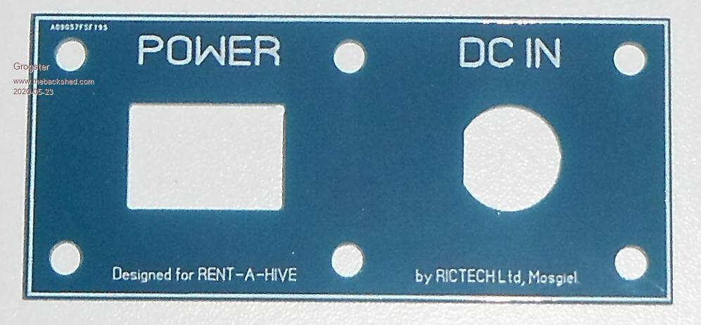 Edited 2020-05-23 15:04 by Grogster Smoke makes things work. When the smoke gets out, it stops! |
||||
Quazee137 Guru Joined: 07/08/2016 Location: United StatesPosts: 603 |
I too like the PCB way. No need to etch Just cut / silk screen. Now days the PCB's can have many colours as the mask. Maybe add a few vias to connect the front and back with a ground solder pad on the back (inside) For the switch up/down/push as long as a power LED lights up does it mater its not pulling much power and we'll get use to it. LOL Edited 2020-05-23 15:28 by Quazee137 |
||||
| Page 1 of 2 |
|||||
| The Back Shed's forum code is written, and hosted, in Australia. | © JAQ Software 2026 |
