
|
|
Forum Index : Microcontroller and PC projects : maxImouse
| Author | Message | ||||
TassyJim Guru Joined: 07/08/2011 Location: AustraliaPosts: 6541 |
The CMM2 has a nunchuk interface built in. It is ideal for fast game action but I have difficulty using them. I find the mouse a much easier device to use. I had a few PS2 mice in the collection so here is a PS2 to serial adapter. The Arduino nano is cheap and ideal for the job. It could also be achieved with a micromite but the Arduino was a cheaper choice and I have yet to tackle CFUNCTIONs I tried to make it suitable for all of the maximite/micromite family but have only tested it on a CMM2 and micromite 170 with 320x240 display. 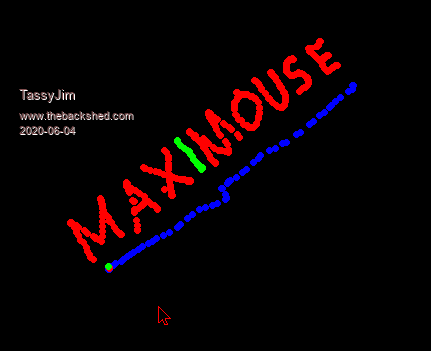 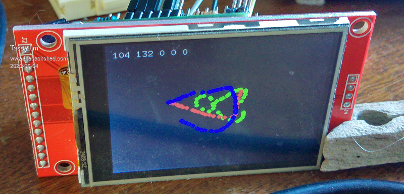 In the Arduino, As usual, someone has already done the hard work. 3 buttons work but not scroll. The PS2 routine takes about 13mS to read the mouse. It takes 2mS to send the 3 bytes of data at 19200 baud. 19200 is the fastest that all mites can handle. On the Arduino, pin 5 goes to PS2 data and pin 6 to PS2 clock. The serial is at 5V so I used a resistor divider to bring the level down to ~3.3V We could update as fast as 16mS to equal the nunchuk but that would cause unnecessary load on the maximite and is of little benefit. I chose a delay of 100mS which is added to the 13mS giving a refresh rate of 114-115mS. In the CMM2, I set the serial to interrupt with 3 bytes in the stream meaning the receiving is all done in the background. There is a chance of the stream getting interrupted so your program will need some way of recovering. I used j$ = INPUT$(255,#2) The interrupt Sub updates some global variables and sets flags to indicate mouse movement or button change. The mousetrap sub takes about 0.15mS on the CMM2 and could be reduced a bit by shifting same of the code into the main loop. 0.15mS every 114mS is not much load. In the demo, the mouse buttons change the colour of the dots. L, R and L+R �' TassyJim Jun2020 �' PS2 mouse to serial interface demo �' Arduino sends 3 bytes �' X movement - signed byte,Y movement - signed byte,Button states - byte �' for micromites that don't do sprites, comment out those lines. �' Maximite running V4.5 will have to change the CIRCLE and TEXT commands �' early Maximites will also need to change Colour and INTEGER � �DIM INTEGER mouseX, mouseY, mouseB, mouseR, mouseL, mouseM �' mouse position and buttons �DIM INTEGER mouseMove, mouseClick ' flags to indicate mouse movement or button change �DIM INTEGER mc ' mouse colour � �SPRITE LOAD "mouse.spr",5 �OPEN "com1: 19200,256,mousetrap,3" AS #2 ' 19200 is the fastest that all Maximie/micromites can handle �initM � �DO � �IF INKEY$ = " " THEN initM ' might be needed if the mouse interface is interrupted. � � � �IF mouseMove = 1 THEN � � �IF mouseX < 0 THEN mouseX = 0 ' keep the pionter on the screen � � �IF mouseY < 0 THEN mouseY = 0 � � �IF mouseX >= MM.HRES THEN mouseX = MM.HRES -1 � � �IF mouseY >= MM.VRES THEN mouseY = MM.VRES -1 � � �drawIt � � �mouseMove = 0 � �ENDIF � � � �IF mouseClick = 1 THEN � � �mouseR = (mouseB AND 2)/2 ' extract the individual button states � � �mouseL = (mouseB AND 1) � � �mouseM = (mouseB AND 4)/4 � � �IF mouseL = 1 THEN mc = RGB(RED) � � �IF mouseR = 1 THEN mc = RGB(GREEN) � � �IF mouseL = 1 AND mouseR = 1 THEN mc = RGB(BLUE) � � �drawIt � � �mouseClick = 0 � �ENDIF �LOOP � �CLOSE #2 � SUB initM �LOCAL j$ �j$ = INPUT$(255,#2) ' flush the serial buffer �mouseX = MM.HRES/2 �mouseY = MM.VRES/2 �CLS �SPRITE SHOW 5,mouseX,mouseY,1 END SUB � SUB drawIt �TEXT 10,10, STR$(mouseX)+" "+STR$(mouseY)+" "+STR$(mouseL)+" "+STR$(mouseM)+" "+STR$(mouseR) �SPRITE HIDE 5 ' hide the cursor while we draw �IF (mouseL + mouseR) > 0 THEN ' only draw if a button is pressed � �CIRCLE mouseX, mouseY, 3, 1,1,mc,mc � �'circle(mouseX, mouseY),3,mc,1,F ' CMM V1 �ENDIF �SPRITE SHOW 5,mouseX,mouseY,1 END SUB � SUB mousetrap �LOCAL INTEGER deltaB, deltaX, deltaY �deltaX = ASC(INPUT$(1,#2)) �' read 3 bytes �deltaY = ASC(INPUT$(1,#2)) �deltaB = ASC(INPUT$(1,#2)) AND 7 �IF deltaX > 127 THEN deltaX = deltaX - 256 ' signed 8 bit integer �IF deltaY > 127 THEN deltaY = deltaY - 256 �IF mouseB <> deltaB THEN � �' �buttons have changed � �mouseClick = 1 � � � � � �' set the flag � �mouseB = deltaB � � � � � ' remember button states �ENDIF �IF deltaX <>0 OR deltaY <> 0 THEN �' mouse has moved � �mouseMove = 1 � � � � � � ' set the flag � �mouseX = mouseX + deltaX � �mouseY = mouseY - deltaY �ENDIF END SUB � /* �PS2 mouse to serial �PS2 clock = pin 6 �PS2 data �= pin 5 �Time taken to read the mouse approx 13mS �1 mS to send data at 38400 baud */ #include "PS2Mouse.h" PS2Mouse mouse(6,5); void setup(){ �Serial.begin(19200); �/* �while(!Serial); �Serial.print("Setup... "); */ �mouse.begin(); �/* �Serial.println("complete!"); �*/ } void loop(){ �uint8_t stat; �int x,y; �mouse.getPosition(stat,x,y); �Serial.write(x); �Serial.write(y); �Serial.write(stat); �delay(100); � } The attached ZIP contains all the Arduino code as well as the maximite code. mouse.zip Jim Edited 2020-06-04 18:01 by TassyJim VK7JH MMedit |
||||
| CaptainBoing Guru Joined: 07/09/2016 Location: United KingdomPosts: 2171 |
Nice! brings mouse support to literally everything (with a serial link) Edited 2020-06-04 18:36 by CaptainBoing |
||||
Grogster Admin Group Joined: 31/12/2012 Location: New ZealandPosts: 9979 |
Excellent work, Jim.   I will have to dig out a nano and try it - I am sure I have one around here somewhere.... Smoke makes things work. When the smoke gets out, it stops! |
||||
| CaptainBoing Guru Joined: 07/09/2016 Location: United KingdomPosts: 2171 |
Hey Grogs, you build panel systems - how about a PS2 trackball mounted in the panel with this gadget. touch is nice but sometimes... on second thought the economies and the complexity around a pointer don't really stack up. but I would be tempted to try Edited 2020-06-04 18:40 by CaptainBoing |
||||
| Grogster Admin Group Joined: 31/12/2012 Location: New ZealandPosts: 9979 |
Food for thought..... I DO like trackballs over mice, but they are even harder to find in PS/2 then standard PS/2 mice are!  Smoke makes things work. When the smoke gets out, it stops! |
||||
| TassyJim Guru Joined: 07/08/2011 Location: AustraliaPosts: 6541 |
I used to modify trackballs for handicapped users. That was an interesting exercise. All done for no charge, just a feel good for me and some very grateful recipients. I wish I had a few of the trackballs in the shed now. My next exercise will be analogue joysticks. I have a nice Microsoft Sidewinder to put to use. Jim VK7JH MMedit |
||||
| Turbo46 Guru Joined: 24/12/2017 Location: AustraliaPosts: 1693 |
Jim, A mouse is the main reason I would have loved the CMM2 to have a second serial port! Are you aware of the Silicon Chip USB Keyboard & mouse adaptor? Also this post and this one? I programmed the 270 chip with the Microbridge. I would still like to add a second serial port to the CMM2 but it all seems a bit clumsy. I could multiplex the one port to produce 2 or more or use a Micromite as a "data concentrator" - not ideal. Bill Keep safe. Live long and prosper. |
||||
| matherp Guru Joined: 11/12/2012 Location: United KingdomPosts: 11570 |
The CMM2 has three serial ports including the console |
||||
| Turbo46 Guru Joined: 24/12/2017 Location: AustraliaPosts: 1693 |
Sorry Peter.  I must have looked at that I/O connector diagram a dozen times and still missed it, Thanks. I must have looked at that I/O connector diagram a dozen times and still missed it, Thanks.Bill Keep safe. Live long and prosper. |
||||
| TassyJim Guru Joined: 07/08/2011 Location: AustraliaPosts: 6541 |
I had forgotten Raros's serial mouse interface and don't subscribe to SC any more. Seeing that some hardware is needed for the interface, a nano works out just as simple. If you are short of serial ports, the Arduino could be changed to act as an I2C slave. That was my first idea - make it emulate the nunchuk. I still might try that sometime. Jim VK7JH MMedit |
||||
Raros Regular Member Joined: 06/02/2012 Location: ItalyPosts: 55 |
Great Byez |
||||
| TassyJim Guru Joined: 07/08/2011 Location: AustraliaPosts: 6541 |
I have added joysticks to the mix. The common Arduino joystick module has it's pots connected between Vcc and Ground so a simple analog read is all that's needed to get the relative position. They usually have one button which switches to ground. The real joysticks from 20 years ago are different. In the real joysticks, there is a ~100k pot connected to 5V but not connected to ground so we get a variable resistance we need to read. In the original systems, there weren't many ADC converters so they measured to time taken to charge a capacitor. This is directly proportional to the resistance. This is the method I used. With minimum resistance, it takes 40uS to charge the 0.01uF capacitor to V/2 and at the maximum resistance about 1200uS My cheap joystick has higher value resistances so it takes up to 1600uS to charge. There are 2.2k resistors on all inputs to limit charging current. The button inputs have 0.01uF filter capacitors. I used a LM324 for the comparitors but any one that runs of 5V single supply will do. To start the timing, the capacitors are discharged for 100uS (this could be shortened a bit). The transistors are not critical and mosfets could be used. We then record when the outputs of the comparitors return low. I divide the result by 4 because the nano has a 4uS resolution. The upper 2 bits of the reading are stored in the button byte to give up to 10 bits resolution. We need the spare room to cater for different joysticks. .png) The MMBasic interrupt routine has changed: SUB mousetrap LOCAL INTEGER deltaB, deltaX, deltaY, device deltaB = ASC(INPUT$(1,#2)) ' read 3 bytes deltaX = ASC(INPUT$(1,#2)) deltaY = ASC(INPUT$(1,#2)) device = (deltaB AND 192 )/ 64 'top 2 bits determine devcie sending data IF device = 0 THEN ' its a mouse PRINT "Mouse "; STR$(deltaX,6,0);STR$(deltaY,6,0);" ";BIN$(deltaB,8) 'DEBUG deltaB = deltaB AND 7 IF deltaX > 127 THEN deltaX = deltaX - 256 ' signed 8 bit integer IF deltaY > 127 THEN deltaY = deltaY - 256 IF mouseB <> deltaB THEN ' buttons have changed mouseClick = 1 ' set the flag mouseB = deltaB ' remember button states ENDIF IF deltaX <>0 OR deltaY <> 0 THEN ' mouse has moved mouseMove = 1 ' set the flag mouseX = mouseX + deltaX mouseY = mouseY - deltaY ENDIF ELSEIF device = 1 THEN ' its joystick A deltaX = deltaX + (deltaB AND &B00110000)*16 deltaY = deltaY + (deltaB AND &B00001100)*64 PRINT "Joy A "; STR$(deltaX,6,0);STR$(deltaY,6,0);" ";BIN$(deltaB,8) 'DEBUG ELSEIF device = 2 THEN ' its joystick B deltaX = deltaX + (deltaB AND &B00110000)*16 deltaY = deltaY + (deltaB AND &B00001100)*64 PRINT "Joy B "; STR$(deltaX,6,0);STR$(deltaY,6,0);" ";BIN$(deltaB,8) 'DEBUG ENDIF END SUB and the Arduino code: /* PS2 mouse to serial PS2 clock = pin 3 PS2 data = pin 2 Time taken to read the mouse approx 13mS 1 mS to send data at 38400 baud */ #include "PS2Mouse.h" const int trigPin = 4; const int axPin = 5; const int ayPin = 6; const int bxPin = 7; const int byPin = 8; const int ab1Pin = 9; const int ab2Pin = 10; const int bb1Pin = 11; const int bb2Pin = 12; uint8_t stat; int x,y,s,so; unsigned long timeZero, timeWait; signed long axt,ayt,bxt,byt; signed long axto,ayto,bxto,byto; int p,ab,bb, abo,bbo; PS2Mouse mouse(3,2); void setup(){ Serial.begin(19200); pinMode(axPin, INPUT); pinMode(ayPin, INPUT); pinMode(bxPin, INPUT); pinMode(byPin, INPUT); pinMode(ab1Pin, INPUT_PULLUP); pinMode(ab2Pin, INPUT_PULLUP); pinMode(bb1Pin, INPUT_PULLUP); pinMode(bb2Pin, INPUT_PULLUP); pinMode(trigPin, OUTPUT); digitalWrite(trigPin, LOW); mouse.begin(); } void loop(){ mouse.getPosition(stat,x,y); s = stat & 0x3F; //make sure the top 2 bits are zero if(x != 0 || y != 0 || s != so){ Serial.write(s); Serial.write(x); Serial.write(y); so = s; } axt = 0; ayt = 0; bxt = 0; byt = 0; digitalWrite(trigPin, HIGH); // discharge the capacitors delayMicroseconds(100); digitalWrite(trigPin, LOW); timeZero = micros(); timeWait = timeZero + 2050; // set timeout while (micros() < timeWait) { if (axt == 0 && digitalRead(axPin) == LOW) { axt = micros()-timeZero; } if (ayt == 0 && digitalRead(ayPin) == LOW){ ayt = micros()-timeZero; } if (bxt == 0 && digitalRead(bxPin) == LOW){ bxt = micros()-timeZero; } if (byt == 0 && digitalRead(byPin) == LOW){ byt = micros()-timeZero; } } /* nano only has 4 uS resolution so divide by 4 add high byte bits to button byte 2 bits to identify mouse or joystick, 2 bits for x axis, 2 bits for y axis 2 bits for buttons */ axt = axt / 4; ayt = ayt / 4; bxt = bxt / 4; byt = byt / 4; ab = (highByte(axt) & 3 )*16 + (highByte(ayt) & 3 )*4 + 64; ab = ab + (1-digitalRead(ab2Pin)) *2; ab = ab + 1-digitalRead(ab1Pin); bb = (highByte(bxt) & 3 )*16 + (highByte(byt) & 3 )*4 + 128; bb = bb + (1-digitalRead(bb2Pin)) *2; bb = bb + 1-digitalRead(bb1Pin); if (ab != abo || axt != axto || ayt != ayto) { Serial.write(ab); Serial.write(lowByte(axt)); Serial.write(lowByte(ayt)); abo = ab; axto = axt; ayto = ayt; } delay(3); // give the micromite time to digest if (bb != bbo || bxt != bxto || byt != byto) { Serial.write(bb); Serial.write(lowByte(bxt)); Serial.write(lowByte(byt)); bbo = bb; bxto = bxt; byto = byt; } delay(1000); } I will bundle it all together once I have transferred the circuitry from breadboard to veroboard and played a bit more. I still have one digital pin free on the Arduino and all the analogue pins so I could add code for the new modules as well. Jim VK7JH MMedit |
||||
| vegipete Guru Joined: 29/01/2013 Location: CanadaPosts: 1181 |
Since you are creating what could likely become the standard interface, may I make a suggestion before it gets too locked in? Boost the size of the data payload a bit. Your current implementation only allows 4 devices, with 2 bytes and 6 bits of info each. Consider the following: - a scroll wheel mouse needs 4 bytes of data. - 2 joysticks (4 axis, 4 buttons) needs 5 bytes of data If you changed to a 6 byte data packet, this would allow 256 devices (or 127 to relate somewhat to I2C) with 5 bytes of data each. Or maybe round to 8 bytes total, because computers like powers of 2. Just a thought. Visit Vegipete's *Mite Library for cool programs. |
||||
| TassyJim Guru Joined: 07/08/2011 Location: AustraliaPosts: 6541 |
The Arduino doesn't have enough pins for more than 4 devices realistically so I prefer to leave it at 4 for my purposes. I am considering a 4th byte to cater for scroll wheel mice and as a 'spare'. I need to investigate why my scroll mouse isn't playing fair. Too many different standards between mice. I already cater for 2 joysticks or joysticks with more than 2 axis. My Microsoft stick has a throttle which I read easily. Device 2 is joystick A and device 3 is joystick B. While more precision sounds like a good idea, I have found that the joysticks send data even when left alone. The output jitters by a couple of bits so I am going to try adding a dead zone so there has to be some definite movement before updating the position. This makes more than 8 bits for position superfluous once a particular stick is calibrated. This is the output from my Microsoft joystick sitting idle: Joy B 81 0 10000000 Joy B 80 0 10000000 Joy A 136 142 01000000 Joy A 138 144 01000000 Joy B 81 0 10000000 Joy A 137 144 01000000 Joy B 80 0 10000000 Joy A 136 143 01000000 Joy A 138 144 01000000 Joy B 82 0 10000000 Joy A 136 143 01000000 Joy B 80 0 10000000 Joy A 136 142 01000000 Jim VK7JH MMedit |
||||
| TassyJim Guru Joined: 07/08/2011 Location: AustraliaPosts: 6541 |
I found a PS2 library that works with my scroll mouse so I have changed to that library and changed the data sent to 4 bytes. I also discovered that trying to do timing while data is being sent in the background is not a good idea so I made a few changes. I also added a 'dead zone' in the joystick routines to limit the number of packets sent while at rest. That allowed me to send data more often. The full Arduino code and the MMBasic demo are included in the ZIP PS2Mouse2.zip A good source for PS2 info is https://isdaman.com/alsos/hardware/mouse/ps2interface.htm Jim VK7JH MMedit |
||||
| Volhout Guru Joined: 05/03/2018 Location: NetherlandsPosts: 5958 |
Hi TassyJim, Maybe I missed the point but why are you decoding the old joysticks the same way it was done 30 years ago(timing) ? It is also possible to use the ADC of the arduino (or whatever) to read the value of the variable resistor in the joystick. Simply connect the old 5V pin to ground, and add 10k pullup resistors to 3.3V to the signal pins. The result may not be linear or full range, but that can be overcome in the arduino code. Volhout PicomiteVGA PETSCII ROBOTS |
||||
| TassyJim Guru Joined: 07/08/2011 Location: AustraliaPosts: 6541 |
2 reasons. Not very linear which made repeatability on one side difficult and some of the hybrid joysticks which were able to work as digital or analogue would not like that arrangement. The third reason (and the most important) was, it was something I hadn't tried before now. Jim VK7JH MMedit |
||||
| vegipete Guru Joined: 29/01/2013 Location: CanadaPosts: 1181 |
How are you interfacing this with the CMM2 given that the mouse and Nano run at 5 volts and the serial ports on the CMM2 external I/O connector are indicated in the manual as being NOT 5 volt tolerant? (Open drain output and pull-ups?) Visit Vegipete's *Mite Library for cool programs. |
||||
| TassyJim Guru Joined: 07/08/2011 Location: AustraliaPosts: 6541 |
I used a resistor divider to bring the level down to ~3.3V 1.8k and 3.3k is my usual choice. We only need Tx from Arduino, I didn't bother connecting the Arduino Rx. Jim VK7JH MMedit |
||||
| The Back Shed's forum code is written, and hosted, in Australia. | © JAQ Software 2026 |
