
|
|
Forum Index : Microcontroller and PC projects : How can I capture this data-stream?(non-standard)
| Page 1 of 2 |
|||||
| Author | Message | ||||
Grogster Admin Group Joined: 31/12/2012 Location: New ZealandPosts: 9915 |
Hello all.  I'm playing keyfob transmitters and receivers again. I have successfully captured the data packets from several fob transmitters, and have saved them all as logicdata files, which I attach here as a ZIP: KeyFobs.zip You will need Saelie Logic to be able to open and examine those, but I think at least a few members here have that software and logic analyser device, and I am hoping they can help me get a MM2 chip to decipher this into something useful. The capture from left-to-right outputs white-noise while there is no valid data, and then the repeating data-packet is shown, followed by more white-noise when I let go of the button. Most of these buttons use the very common 1527 encoder or the 2260/2262 encoder chips. I need to be able to capture at least one valid packet of the data from these and save it somewhere, to be compared to a list of valid buttons when one is pressed(essentially a learning-receiver), but as it is just a bit-stream and not any predefined protocol such as asynchronous serial, I am wondering HOW to go about it. Protocols are a good thing, and I use most of them(UART/I2C/SPI etc), but just a bit-stream packet that can be anything, and arrive at any time, I am wondering how to intercept it and save the data-packet. Armed with the captures, I can see that the data-packet is preceded by a constant low lasting about 13ms or so, and that short low repeats between data packets, so this gives me something to sync from - look for the low-going signal, then read the bits till the data goes low again for about another 13ms, and assume that is your data-packet, but HOW? First thought was an interrupt, but I need a way to trip the interrupt ONLY if the "Data" pin goes low for at least 13ms or so. I was initially thinking that have an interrupt on the data pin, trip when the pin goes low, measure for at least 10ms, and if still low, then assume the data-packet is immediately forthcoming - BUT the problem is that while the receiver outputs white-noise, the interrupt will be driven nuts by the random low-going pulses, and it will get stuck in there and never get out again.  Can anyone give me any pointers on where I should be starting to think about how to do this, cos I am lost without a protocol to work with on this kind of thing.  Datasheets might help some members here help me with this, so here is the 1527 encoder datasheet, which shows the data-packet format on page 2: EV1527.pdf pt2262_1.pdf 2262 formats are described on pages 5,5 and 6 of its PDF above. From both of these, I can see how the encoder builds it data-packet, but I can't get my brain to think about how I decode it inside a MM2 chip. The 2262 has a matching decoder chip(2272), which makes for a nice painless arrangement, but the majority of fobs seem to use the 1527 encoder chip, and I can't find a module that will receive transmissions from those, and just output a serial data-stream of the code they send. Well, technically, I DID find ONE module that does that, but it is US$10 a pop, and I figure the MM2 should be able to read this data without too much coaxing.  Can any of the members here spare me a few seconds to look at the data captures, and the two PDF datasheets and help me find a way to read the data into a variable or something inside a MM2 chip? Thanks for anyone who can help. I am somewhat lost at this raw bit-stream level of things - I like my predefined protocols!  Smoke makes things work. When the smoke gets out, it stops! |
||||
disco4now Guru Joined: 18/12/2014 Location: AustraliaPosts: 1109 |
Hi, I looked at the first one. Looks like a 24 bit code repeated several times. Basically a short pulse up then long pulse down is Ā0 Ā Ā Ā Ā Āa long pulse up then short down up is Ā1 (or the other way round) short looks like 0.44ms and long 1.48ms ie about a 3:1 ratio See this thread for decoding a similiar 32 bit code. Digoo decoding What are you receiving the signal with, is it 433Mhz. Regards Gerry Edited 2020-06-26 10:43 by disco4now F4 H7FotSF4xGT |
||||
TassyJim Guru Joined: 07/08/2011 Location: AustraliaPosts: 6496 |
I thought you had a receiver module that has squelch out. That will save wading through the white noise. Jim VK7JH MMedit |
||||
| Grogster Admin Group Joined: 31/12/2012 Location: New ZealandPosts: 9915 |
@ disco4now: Yes, it is a sequence of bits, repeating for as long as you hold the button. ĀI will check out your link. ĀThanks. ĀYes, it is 433MHz.@ Jim: Yes, I did(and still do) for the 2262/2264 transmitters. ĀYou can get a decoder module for a couple of bucks that has the receiver AND a decoder chip on it, and it just outputs BCD for the data bits(0-15) on four data lines along with a VT(Valid Transmission) line, which you can detect with an interrupt, then read the four data lines with the PORT command - dead easy, and works beautifully. ĀBut more and more buttons now are using the 1527 chip, each one of which, has a different random address that you CANNOT set yourself, so I need a way to read those ones more and more now as they become the more common encoder over the 2262/2264. I love the 2264 et el as mentioned, as most of the older keyfobs that used that chip, had tiny little solder-blob pads, and you could then set the code it transmitted simply by blobbing the pads for the code you wanted. ĀYou CAN'T do that with the 1527, as the address is set at the factory and every chip has a different random address - which complicates things, as each single chip has to be 'Learned' by whatever the receiver/decoder is. EDIT: Just realized/remembered that I had a thread about this back in 2018. I have found it, and it is here. I will re-read that one now, to find out where we got up to, but any new replies or ideas, please post them on this thread. Edited 2020-06-26 14:40 by Grogster Smoke makes things work. When the smoke gets out, it stops! |
||||
| SimpleSafeName Guru Joined: 28/07/2019 Location: United StatesPosts: 351 |
This video gives a quick and dirty way of capturing and decoding the signal: https://www.youtube.com/watch?v=LbCDpbWrdlQ |
||||
| KeepIS Guru Joined: 13/10/2014 Location: AustraliaPosts: 2075 |
I can't read the logic files, but it's just pin in bit bashing, I'm with Jim and I don't know why it doesn't have a squelch pin (valid signal and not noise) in any case if the random atmospheric noise doesn't produce a 13ms low then it's simply a matter of getting the packet delimiter (13ms low) and reading the pin every t1 period for the packet bits. t1 period set to put you in the middle of the bit time period obtained from the logic analyser. NANO:Inverter V 8.2ks -┬ĀLinux AvrDude GUI script V4.0 |
||||
| KeepIS Guru Joined: 13/10/2014 Location: AustraliaPosts: 2075 |
Just had a quick peek at that and you may have trouble with timing very short delays on the CMM2. I must gets out the DSO and see what the shortest total time period is, allowing for MMBasic pin read, save and ready to read cycle. I do this on the ArmH7 but with 24 bit data and longer time periods. NANO:Inverter V 8.2ks -┬ĀLinux AvrDude GUI script V4.0 |
||||
| SimpleSafeName Guru Joined: 28/07/2019 Location: United StatesPosts: 351 |
Oh, and I forgot. Here are the files that Grogster provided, exported to CSV format. KeyFobs2CSV.zip |
||||
| Grogster Admin Group Joined: 31/12/2012 Location: New ZealandPosts: 9915 |
@ SimpleSafeName: Thanks for the video link, I will check it out. @ KeepIS: "...if the random atmospheric noise doesn't produce a 13ms low then it's simply a matter of getting the packet delimiter (13ms low) and reading the pin every t1 period for the packet bits. t1 period set to put you in the middle of the bit time period obtained from the logic analyser." Huh? Lost..... Can you please elaborate. Please define "t1". I only understand pre-defined protocols, and am completely hopeless with bit-banging techniques. On the squelch, page 18 of the 470 receiver chip states:  My receiver modules have no connection to the CTH pin(7), so I could do as they suggest and add a 6M8 to 10M resistor from this pin to GND as a squelch experiment. Also, pin 12(WAKEB) is defined in the manual as: "Wakeup(digital output): Active-low output that indicates detection of an incoming RF signal." - this pin is also not connected on the module I have. I will solder a test wire to this, and analyse it along with the data signal, cos this could indeed provide the interrupt signal I need, and then I can just read the data bits somehow. Smoke makes things work. When the smoke gets out, it stops! |
||||
| KeepIS Guru Joined: 13/10/2014 Location: AustraliaPosts: 2075 |
I had a quick look at that thread and the guys there have shown a few ways to do what you want. This type of data is asynchronous so it has no clock, your normal serial port communications is also asynchronous but uses a pre defined standard of timing values with start and stop bits, the data bits are clocked out at a known bit rate and intelligent convertors can also partly sync to the data rate. So t1 would be the bit rate, or the time between each bit slot. In your case, there is no serial data standard, the start and stop bits are replaced by a packet delimiter that has a longer period than the data rate and can be either hi or low, how else are you going to know when to start timing the incoming packet data transition period t1. That other thread shows some unique ways of decoding the stream, I like TassyJims use of PWM to trigger an interrupt at t1 rate, adjusted for overhead. Count 24 t1 slots, read the pin state each count, assemble you binary packet, wait for the next delimiter and repeat. However some fast data rates need a C-Sub to sidestep MM basic overheads. There appeared to be timing periods in the usec range in one of those youtube videos, so a few simple tests could reveal if the CMM2 can handle that. It would be simple to do in assembler in small PIC. EDIT: just had a look with a DSO and the CMM2 should do it easily, the only real overhead will be forming the packet inside the loop, but with the optimisation in the CMM2 it should not have the slightest problem doing so. . Edited 2020-06-26 19:48 by KeepIS NANO:Inverter V 8.2ks -┬ĀLinux AvrDude GUI script V4.0 |
||||
| Grogster Admin Group Joined: 31/12/2012 Location: New ZealandPosts: 9915 |
Thanks - that helped me understand it more compared to "Standard" UART serial. I have already pulled out the experimenting code from that other thread I had forgotten I had even posted(whoops!  ) and I will be doing some more experimenting over the weekend. ) and I will be doing some more experimenting over the weekend.Smoke makes things work. When the smoke gets out, it stops! |
||||
| TassyJim Guru Joined: 07/08/2011 Location: AustraliaPosts: 6496 |
Have a look at pin 12. WAKEB Wakeup (Digital Output): Active-low output that indicates detection of an incoming RF signal That should give you the squelch we are looking for. After you have that working, we can start looking at decoding. Jim VK7JH MMedit |
||||
| Grogster Admin Group Joined: 31/12/2012 Location: New ZealandPosts: 9915 |
Hello Jim. I've been re-reading the thread from back in 2018, and have been playing with the code you posted back then. I did solder a wire on WAKEB(pin-12), and connected that to my logic analyser, then pressed a button, but got absolutely no change whatsoever from the pin. I think this module I am playing with, uses a clone chip, cos there are NO markings on it at all, so I fully expect it is an 8-pin version, inside a 16-pin case. I'm going to hunt out some more modules, cos I know I DO have modules that have the SYN470 markings laser engraved on the chip, so I think I am probably wasting my time to some extent with the unmarked chip ones, but that was all I could find rummaging around my messy workshop bins.... I want to persevere with this problem, because it gives me the chance to learn something new, because bit-banging techniques have always confused the hell out of me, even though they are probably older then the protocols like Async Serial etc!  I only hate bit-banging, because I don't fully understand it, so if I can learn something from all this, I expect(and hope) that this will become more clear to me as I delve deeper into it. Smoke makes things work. When the smoke gets out, it stops! |
||||
| JohnS Guru Joined: 18/11/2011 Location: United KingdomPosts: 4281 |
What's the min time between bits (roughly)? It'll tell you what your chances of bitbanging are and whether MMBasic is fast enough or you need a C func. John |
||||
| vegipete Guru Joined: 29/01/2013 Location: CanadaPosts: 1167 |
When I have done this sort of decoding in the past, I counted the pulses and used the count to determine what I had. The length of the gap between packets let me know when one packet ended and the next began. My receive code had to function with both a 12 bit and 24 bit packet. The 24 bit packet was actually 12 2-bit pairs. I counted bits, waiting for a longer gap, because there was no guarantee I was properly receiving the start of the first packet. Typically, the first 8/16 pulses were the binary code for the particular transmitter and the last 4/8 bits were the individual button states. I never looked at the data packets for transmitters with more than 4 buttons. Transmitters could be programmed with a 'unique' code (1 of 256) by setting 8 address bits either high or low (with dip switches on better ones, solder bridges on cheaper ones.) The 24 bit transmitters were interesting because they actually understood 3 states per bit: high, low or floating. This was transmitted by making the 2 bits of a pair opposite. And as Gerry posted, the relative duration of the high and low of a bit determined a 0 or 1. For a test, feed the bit stream to a UART set to various baud rates and see if consistent nonsense is received. If it is consistent, it isn't nonsense. ;-) BTW, my original assembly code ran on an 8 bit PIC16F627 with a 4MHz oscillator. Visit Vegipete's *Mite Library for cool programs. |
||||
| Grogster Admin Group Joined: 31/12/2012 Location: New ZealandPosts: 9915 |
@ JohnS: space between data bursts is about 13ms, time between bits is about 1.2ms - 1.8ms depending on the transmitter type. Jims E64 code does work, and I am playing with that again now. See the 2018 thread I linked to above to find his code. I don't think the MM2 is fast enough, but the MM+ series of chips do seem to be able to cope with this task, based on my revisiting the 2018 thread. Smoke makes things work. When the smoke gets out, it stops! |
||||
| robert.rozee Guru Joined: 31/12/2012 Location: New ZealandPosts: 2498 |
have some remotes and an SYN470R receiver module here, and just looking at a scope trace of what is going on. in my case, i'm seeing a long negative pulse interval of a little under 9ms between code block. each block consists of 25 bits, with the first (start) bit='0': 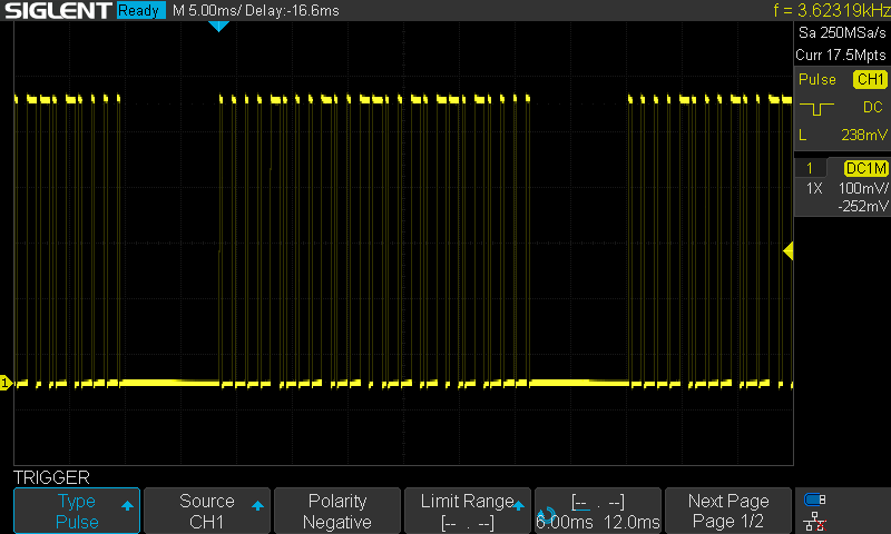 code pulses are about 0.3ms (short) and 0.9ms (long). i have an idea: lets say we aren't worried about the very last bit, which encodes for buttons number 9 to 16. this makes life a little easier as we can then only act upon the rising edges of the data stream (see below). now what if you had THREE pins connected in various ways to the data output from the receiver: 1. an interrupt pin connected directly that triggers on the RISING edge of pulses, 2. an analog input pin connected via an integrator (a series resistor to the receiver's output, and a capacitor from the analog pin to ground), 3. an output pin connected to the analog input pin that can be used to 'zero' the integrator at the end of each 'digit' read. upon each interrupt occurring, you would: A. check if the time interval since the last interrupt was greater than 6ms. if so, clear a buffer string CODE$="", then exit ISR (we are at start of code block). B. if length of CODE$ =24 then exit ISR (we are reading static). C. read the analog pin, D. write '0' to the reset pin and set it as an output, E. set the reset pin as an input. F. if analog value read < threshold then CODE$=CODE$+"0" Ā Ā Ā Ā Ā Ā Ā Ā Ā Ā Ā Ā Ā Ā Ā Ā Ā Ā Ā Ā Ā Āelse CODE$=CODE$+"1" G. if length of CODE$ =24, then print it out (or check if it matches) i'm thinking that with the right choices of integrator components the value read from the analog pin would be: -> near zero for a short-HI followed by long-LOW -> a volt or so for long-HI followed by short-LOW of the 25 bits, we are reading the start bit and only 23 of the 24 data bits, but that shouldn't matter too much in Grogster's application. cheers, rob Ā :-) addendum: looking at what the 'A' and 'B' buttons do on my remote, it appears that the first bit is in fact valid data, and the 25th bit is a dummy stop bit. so we are capturing all the valid data in the above scheme. Edited 2020-06-28 23:09 by robert.rozee |
||||
| Grogster Admin Group Joined: 31/12/2012 Location: New ZealandPosts: 9915 |
Yes, the blank chip on the module I first played with is not a genuine chip. ĀI get nothing at all out of pin-12 when I solder a test wire onto that pin, but I DO get an expected response from another module that has a laser-engraved SYN470R marking on it: 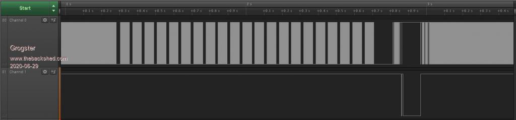 Data on channel-0, WAKEB pin(12) on channel-1. I do note that the pulses we see on WAKEB are at the END of the transmission, NOT the start as I would have thought. ĀTo me, that does not make much sense, as the data has STOPPED by the time you get the pulse on WAKEB - so you have nothing but white-noise again. ĀConfused by the timing of the WAKEB pulse, as the manual for the chip says this is active-low on detection of an incoming RF signal, but it would seem to be active-low on detection of the END of an incoming RF signal. ĀDoes this make any sense to anyone else? Here is another shot, where I have keyed the transmitter four times with a gap between presses, and you can clearly see that the WAKEB pulses DO sync up with the RF, but they appear when I RELEASE the transmitter button, so they are indicating when I am letting go of the transmitter button, but not when the RF is actually detected so you can sync to the data - which is to the left of those pulses, on channel-0. 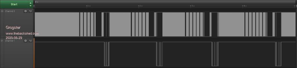 Confusing....  Ā Ā Here are the two logicdata files in a ZIP: 2264logicdata.zip Edited 2020-06-29 14:21 by Grogster Smoke makes things work. When the smoke gets out, it stops! |
||||
| robert.rozee Guru Joined: 31/12/2012 Location: New ZealandPosts: 2498 |
hi all, Ā Āgive the following a try. it runs (only just) on an MX170 and decodes both of the keyfobs i have here. it should also work for fobs with different numbers of data bits by editing or commenting out the line that reads "If (I2-I1-1)<>49 Then Print ".";: GoTo skip" the timing should auto-adjusting. just hook up the output of your SYN470R module to pin 22. the 'getcode' routine could possibly be moved into a timer ISR with some benefit, or better still run on an E64 module. a really useful thing would have been a way to turn on/off all interrupts during the critical part of the code - something like CPU INTERRUPTS ON|OFF the code is quite rough, but is a good starting point and proof-of-concept. cheers, rob Ā :-) CPU 48 Option break 0 SetPin 22, DIN Dim times(150) Dim keylist%(20) Sub getcode Āstate=0 ĀFor I=0 To 148 Ā Ācount=0 Ā ĀDo :count=count+1:Loop Until (Pin(22)=state) Ā Ātimes(I)=count Ā Āstate=Not state ĀNext I End Sub ' main program begins here For I=149 To 150: times(I)=9999: Next I For I=1 To 20: keylist%(I)=&hDEADC0DE: Next I keylist%(15)=&h000077377777732A keylist%(16)=&h00007737777772CA keylist%(17)=&h000077377777734A keylist%(18)=&h000077277777732A keylist%(19)=&h00007727777772CA keylist%(20)=&0000h77277777734A Print "press 'esc' to exit, space bar to add fob code, '?' to list saved codes" Do ĀPause 500 Āgetcode ' find maximum time value, use 1/4 of this as threshold for start/end pulse Ātv=0 ĀFor I=1 To 148:tv=Max(tv,times(I)): Next I Ātv=tv/4 ' find beginning and end of a (possibly) valid code segment ĀI=1 ĀDo While times(I)<(tv): I=I+1:Loop ĀI1=I: I=I+1 ĀDo While times(I)<(tv): I=I+1:Loop ĀI2=I Ācode%=0 ĀIf (I2-I1-1)<>49 Then Print ".";: GoTo skip ĀPrint ' scan over code segment, find maximum and minimum values Āt0=+9999 Āt1=-9999 ĀFor I=I1+1 To I2-1: t0=Min(t0, times(I)): t1=Max(t1, times(I)): Next I Āav=(t0+t1)/2 ĀFor I=I1+1 To I2-1 Ā ĀPrint times(I); Ā Ācode%=code%<<1 Ā ĀIf times(I)>av Then code%=code%+1 ĀNext I ĀPrint ĀPrint I1,I2,, I2-I1-1,, times(I1), times(I2),, Str$(av,0,1),Str$(tv,0,1) ĀPrint Hex$(code%, 16) ĀPrint Bin$(code%, 64) ĀPrint Āskip: ' check for a match to a saved code, beep if found ĀFor I=1 To 20 Ā ĀIf code%=keylist%(I) Then Print Chr$(7) ĀNext I ' press space bar to add fob code to list (max 20) Ākey$=Inkey$ ĀIf key$=" " Then Ā Ākeylist%(index+1)=code% Ā Āindex=(index+1) Mod 20 ĀEndIf ' press '?' to print out the list of saved fob codes ĀIf key$="?" Then Ā ĀPrint Ā ĀFor I=1 To 20 Ā Ā ĀIf keylist%(I)<>&hDEADC0DE Then Print Hex$(keylist%(I), 16) Ā ĀNext I Ā ĀPrint ĀEndIf ĀIf key$=Chr$(27) Then Exit Do Ākey$="" Loop > RUN press 'esc' to exit, space bar to add fob code, '?' to list saved codes ..... 1 5 1 5 1 5 1 5 5 1 1 5 1 5 1 5 5 2 1 5 1 5 4 2 5 1 1 5 1 5 5 1 1 5 5 1 5 1 1 5 5 1 1 5 1 5 1 5 1 1 Ā Ā Ā 51 Ā Ā Ā Ā Ā Ā Ā49 Ā Ā Ā Ā Ā Ā Ā19 Ā Ā Ā73 Ā Ā Ā Ā Ā Ā 3.0 Ā Ā 18.2 0000AB2xxxxxx32A 0000000000000000101010110010101100101101001011001101001100101010 ........ > Edited 2020-07-01 05:49 by robert.rozee |
||||
| Grogster Admin Group Joined: 31/12/2012 Location: New ZealandPosts: 9915 |
Awesome! Thanks, Rob, I will load this into a 170 and try it out. Smoke makes things work. When the smoke gets out, it stops! |
||||
| Page 1 of 2 |
|||||
| The Back Shed's forum code is written, and hosted, in Australia. | © JAQ Software 2026 |
