
|
|
Forum Index : Microcontroller and PC projects : CMM2: DS18B20 Temp sensor problem
| Page 1 of 7 |
|||||
| Author | Message | ||||
| Amnesie Guru Joined: 30/06/2020 Location: GermanyPosts: 757 |
Hello again, after testing three DS18b20 temperature sensors on the CMM2 I only get inconsistent readings. I uploaded a short video, here you can see the problem. https://www.youtube.com/watch?v=Hrb1qnWUNaE Again the first question after seeing this would may lead to the assumption, that my wirering is not right or there is a bad connection. No after the first tries, I soldered the sensor directly to the pins on the mainboard (and yes even meassured them). I used the connectors right on the mainboard for the DS18b20! Yes, 4,7k Ohm resistor is onboard. My code used in this video above: Do print "Temperatur: ", tempr(42) Loop I also tried a pause up to 4 sek. but nothing changed in the "1000" reading, which means "Error", accordingly to the manual. The fact that I tried three "different" / seperate ds18b20 leads me to the assumption that there must be some other problem... The sensors do work, because I used them in other projects with my atmega328p :) Never seen a problem like this. Do you have any suggestions for me? Greetings Daniel Edited 2020-07-14 23:02 by Amnesie |
||||
Chopperp Guru Joined: 03/01/2018 Location: AustraliaPosts: 1126 |
Hi Have you tried just typing:- �Print tempr(42) �from the > prompt ? It should come back with a sensible reading if your setup is correct. Brian Edited 2020-07-14 23:33 by Chopperp ChopperP |
||||
| Amnesie Guru Joined: 30/06/2020 Location: GermanyPosts: 757 |
Hi, yes, tried that, too. Most of the time it returns "1000". |
||||
| Poppy Guru Joined: 25/07/2019 Location: GermanyPosts: 486 |
Have You already read this? Your DS18B20 temperature sensor is likely a fake, counterfeit, clone...  Andre ... such a GURU? Andre ... such a GURU? | ||||
| Chopperp Guru Joined: 03/01/2018 Location: AustraliaPosts: 1126 |
These things can be frustrating. From the video, it does work occasionally so it must be wired the right way around. Have you tried using a pin on the expansion socket? ChopperP |
||||
| matherp Guru Joined: 11/12/2012 Location: United KingdomPosts: 11519 |
Just tried it on V and Y procs, motherboard and single board version - perfect in all cases. Check the 4K7 is actually 4K7 and not 470 or 47K etc. Edited 2020-07-15 00:28 by matherp |
||||
| Amnesie Guru Joined: 30/06/2020 Location: GermanyPosts: 757 |
I bought mine from the list, which is on your link (official distributor). Of course it could be that it is an counterfeit. I mean almost every single chip nowadays is a counterfeit part. This is annoying. But anyway, for all my atmega328 projects all three sensors work. Hm... Because I got only insulated, waterproof sensors, I can't look whether my chip has laser engraving or not. Other tests are - at least for now - to complicated. I am not really sure, how I could drive the ds18b20 without the "tempr(pin)". So any advice for some manual code would be good. Argh... maybee I should simply switch to a 10K NTC as temp-sensor... But they aren't as accurate... Greetings Daniel |
||||
| Poppy Guru Joined: 25/07/2019 Location: GermanyPosts: 486 |
Page 39 of the Manual: "eternal" = "external"?!? Andre ... such a GURU? | ||||
| Amnesie Guru Joined: 30/06/2020 Location: GermanyPosts: 757 |
@ matherp I just tried the external pin 24: � print tempr(24) It is the same "pattern". Most of the time "1000" with a few correct readings in between. This time I wired everything seperatly on breadboard and checked the contacts. Yes my external test was with the correctly meassured 4,7kOhm and my resistor @ pin 42 is also correct 4,7kohm. So even an fully externaly wired ds18b20 at a different pin (24) has the same behavior. I don't really think the firmware is the problem. I think I have a counterfeit chip, but anyway, why all my chips work with my atmega328 projects? Okay.. okay.. I am honest, I am using a ds18b20 library for that... But.. hm. And I am not expecting from you to solve (AGAIN!) others (maybe counterfeit) errors by cloning the chip. It is just bad to come across this kind of errors or failure... But I am glad you could solve others failure in my PS/2 / USB keyboard, by adapt your firmware! Edited 2020-07-15 00:53 by Amnesie |
||||
| Poppy Guru Joined: 25/07/2019 Location: GermanyPosts: 486 |
If You don�t get those chips to work properly, then You can send them to me and I will check them on a Duinomite or you try first on Your CMM1 as well. Andre ... such a GURU? | ||||
| Amnesie Guru Joined: 30/06/2020 Location: GermanyPosts: 757 |
Hi Andre, thank you, first I will try some other ideas. Maybe ask google whether there are some software / timing (?) issues with the clone ones. Maybe the clone sensor (IF it is a clone / counterfeit) needs to be "initialised" slightly different. Because the sensor works. The readings between the "1000"'s are correct. Maybe the counterfeit chip is slower? We may never know... But since those counterfeit chips are so common everywhere, we will see if in the future other maximite users will have the same problems. Edited 2020-07-15 01:02 by Amnesie |
||||
| matherp Guru Joined: 11/12/2012 Location: United KingdomPosts: 11519 |
Just as an experiment try the attached CMM2V1.5.zip |
||||
| Amnesie Guru Joined: 30/06/2020 Location: GermanyPosts: 757 |
Thank you for responding so fast! sadly nothing has changed. To be preceise: I also looked for more correct readings than before in contrast to the "1000" (error). But the pattern seems to be the same. Most time "1000" with a few coincidential correct readings (but can't figure a real pattern, to delimit it from pure coincidence). I tried your new firmware with the "internal" / directly soldered d18b20 @ pin 42 as well as a fully external (with 4,7kohms) @ pin 24.... both readings are full of "1000" :( As I said, bad connection is not the problem. I am very accurate and even meassure connections or Vcc (it is right at 3,33Volt @ sensor Vcc) before I open a topic here. If it matters: With respect to GND, right at the sensor pin, the voltage is @ 2,976volt. But thank you for you help! Greetings Daniel Edited 2020-07-15 02:22 by Amnesie |
||||
| lizby Guru Joined: 17/05/2016 Location: United StatesPosts: 3784 |
FWIW, and YMMV, I plugged this into the external port (with another wire on the bare pin): 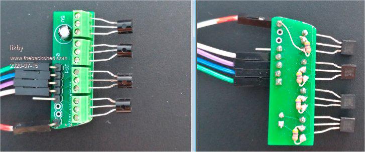 I plugged the other ends of the data pins into 36, 37, 38, 40, and touching a finger to one or another of the DS18B20s, got this: > print tempr(36),tempr(37),tempr(38),tempr(40) 24.75 25 25.125 25 > print tempr(36),tempr(37),tempr(38),tempr(40) 27.75 27.875 29.25 25.3125 > print tempr(36),tempr(37),tempr(38),tempr(40) 30.4375 26.875 28.3125 25.25 > print tempr(36),tempr(37),tempr(38),tempr(40) 28.625 28 27.25 29.25 > print tempr(36),tempr(37),tempr(38),tempr(40) 26.875 27.6875 26.5625 29.3125 I'd say these are almost certainly counterfeits. PicoMite, Armmite F4, SensorKits, MMBasic Hardware, Games, etc. on FOTS |
||||
| Amnesie Guru Joined: 30/06/2020 Location: GermanyPosts: 757 |
Hi lizby, in other words, they work for you. Hmpf.... But why I have got those strange readings? If it wouldn't work at all, but for 30% the time it works. It can't be a bad connection (even not at the waveshare pin) because I used different pins and cables, too. The one at pin 42 is even soldered directly! It can't be the sensor itself (maybe if it is counterfeit?) because I tried three seperate ones which ALL work on my atmega328! It can't be the code... I mean I tried even on the cmd-prompt "print tempr(42)" All resistors (4,7kohm) I used, are meassured, not guessed by looking at the rings. The supply voltage is exactly 3,3volts. On my other atmega328 projects my supplyvoltage was 5volts. But the sensor obviously should work with both... There must be some curse on me :D Edited 2020-07-15 04:45 by Amnesie |
||||
| matherp Guru Joined: 11/12/2012 Location: United KingdomPosts: 11519 |
Please try the following do tempr start 42 pause 300 ? mm.onewire, tempr(42), mm.onewire loop Then load: CMM2V1.5.zip and try your original loop but print mm.onewire as well as the temperature and also my test prog Edited 2020-07-15 04:46 by matherp |
||||
| Amnesie Guru Joined: 30/06/2020 Location: GermanyPosts: 757 |
Hi, I will try it now and report if it works! |
||||
| Poppy Guru Joined: 25/07/2019 Location: GermanyPosts: 486 |
I hopefully think that I still have some flying around, cheap chinese ones ... but generally working. I could send you some for counter testing.  Andre ... such a GURU? Andre ... such a GURU? | ||||
| Amnesie Guru Joined: 30/06/2020 Location: GermanyPosts: 757 |
Hm, Your program BEFORE updating the firmware: 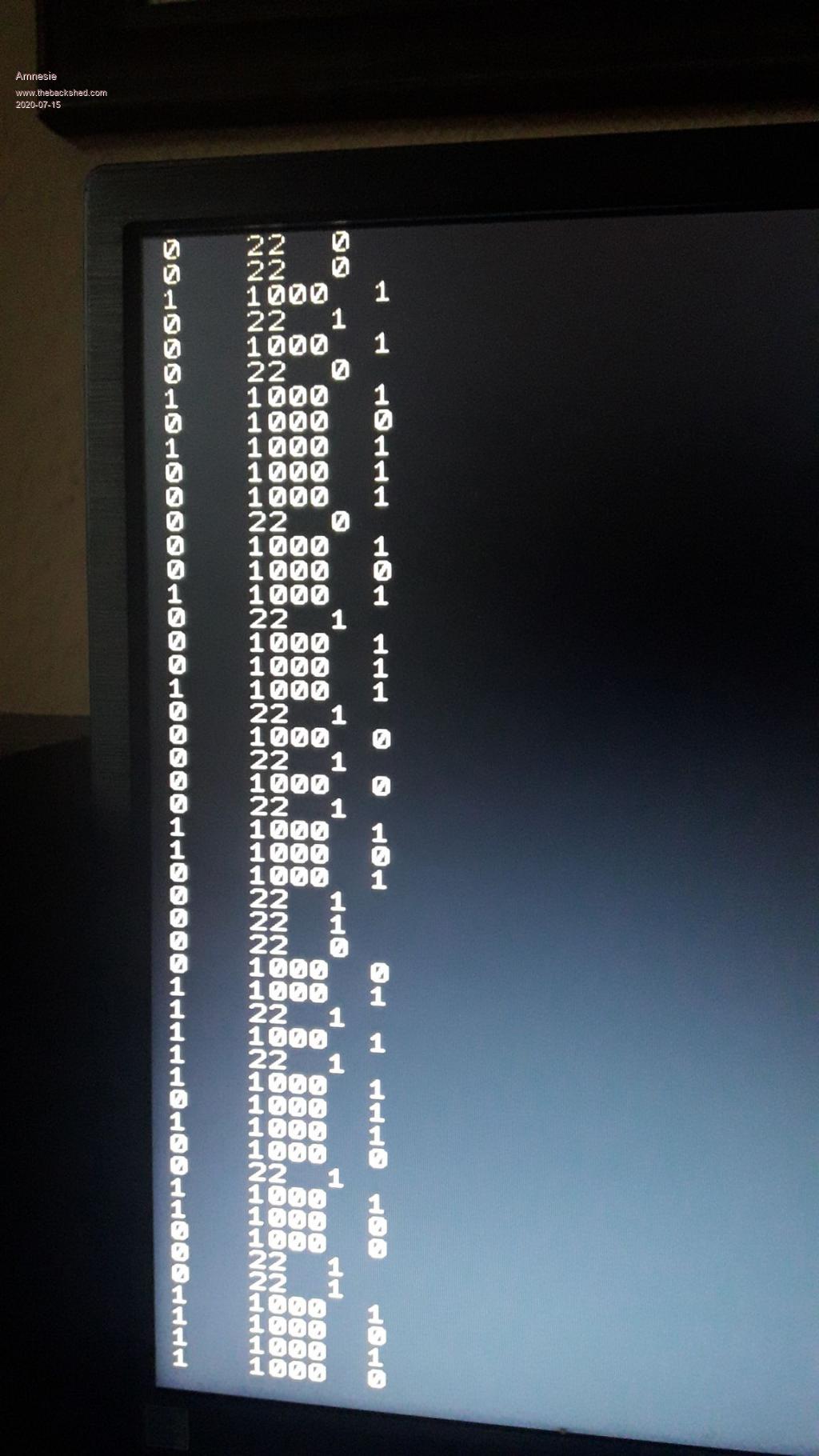 Your program AFTER updating the firmware: 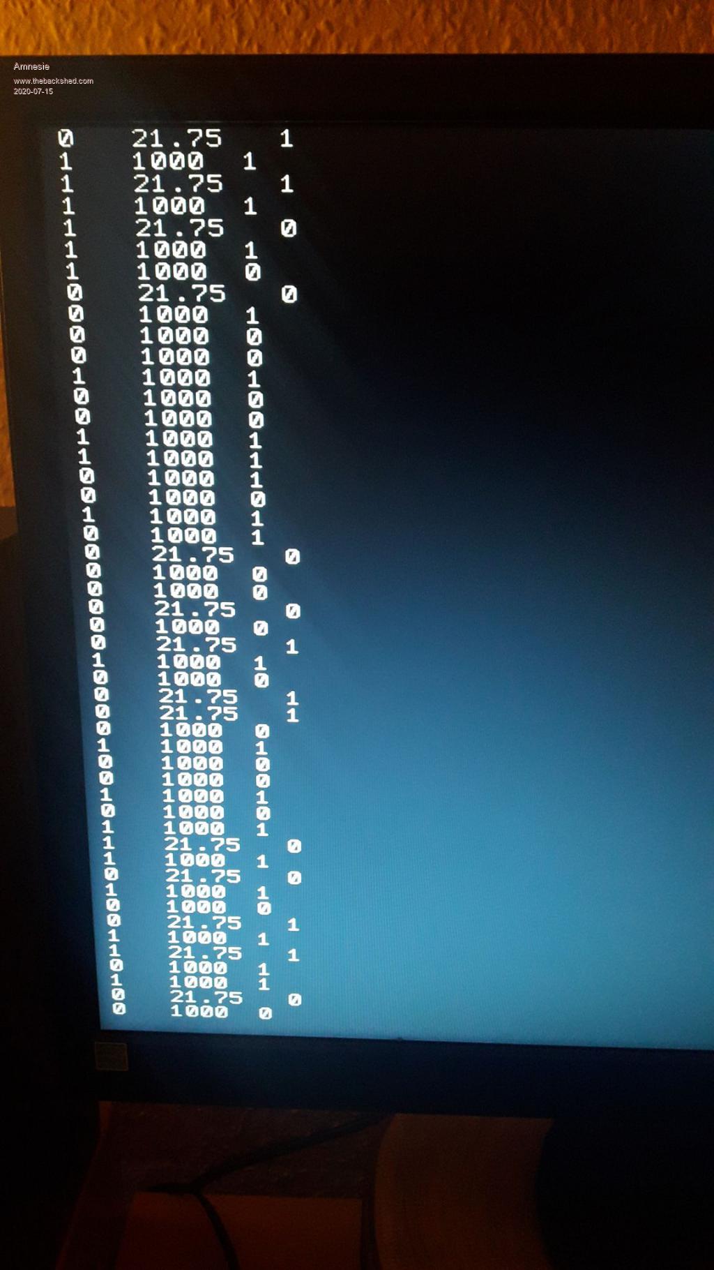 I just ordered 100% original sensors at a german distributor... But something in my head says there must be a good reason for this... Because they generally work! But not with the maximite. When I say "work" I mean all the time... I have never ever seen before any false reading with my atmega328. Maybe some additional info; the error readings are independent from the actual temperature. No matter if I touch the sensor or not, the amount of errors are pretty much the same. Edited 2020-07-15 05:28 by Amnesie |
||||
| Volhout Guru Joined: 05/03/2018 Location: NetherlandsPosts: 5934 |
Hi Amnesie, It is fact that the DS18B20 runs from 3.0V...5.5V. If 1 wire is used there is voltage drop across the 4.7k resistor, and you may be looking at 3V at the chip (not 3.3V), I think you even measured 2.97V or so. Not sure if you are using "parasite port, or external power on the DS18B20's. Assuming parasite power: Since these DS18B20's work well on 5V, the bus voltage may be the problem. Just on the edge. What you could do...the CMM2 also has +5V at the connector. Please leave the 4.75k pullup to 3.3V, and add a second resistor 22k to +5V. This will lift the 3V at the DS18B20 to roughly 3.3V. That is not sufficient for the STM32 to have a problem, but could force the DS18B20's to work. Volhout P.S. matherp, do you distinguish between parasite power and external power (in other words, do you actively pull the IO pin high when there is no communication ?). 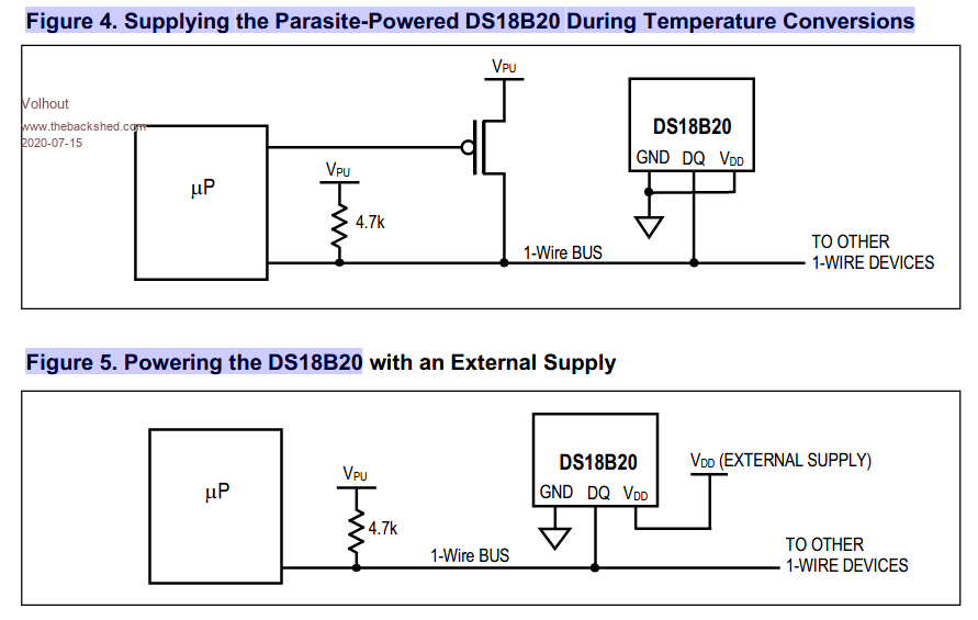 Edited 2020-07-15 06:02 by Volhout PicomiteVGA PETSCII ROBOTS |
||||
| Page 1 of 7 |
|||||
| The Back Shed's forum code is written, and hosted, in Australia. | © JAQ Software 2026 |
