
|
|
Forum Index : Microcontroller and PC projects : Armmite F4 - alternate ?
| Page 1 of 2 |
|||||
| Author | Message | ||||
| Volhout Guru Joined: 05/03/2018 Location: NetherlandsPosts: 5806 |
I stumbled upon this one: Smaller F4 board There is no LCD interface, the RTC battery must be wired external. The 44 pin headers have the IO pins arranged identical to the board I am using now, but the power pins are at different location. 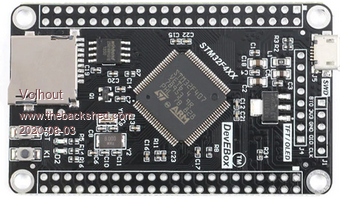 I have ordered one, and will test if MMBasic runs on it. Volhout P.S. haven't found schematics yet, so not sure it works... PicomiteVGA PETSCII ROBOTS |
||||
| lizby Guru Joined: 17/05/2016 Location: United StatesPosts: 3696 |
Interested to know what you find out. The STM32F407VE is the 100-pin 512KB version; the STM32F407VG is the 100-pin 1MB version. PicoMite, Armmite F4, SensorKits, MMBasic Hardware, Games, etc. on FOTS |
||||
| Volhout Guru Joined: 05/03/2018 Location: NetherlandsPosts: 5806 |
I finally found readable schematics (on the micropython github site). It looks possible to put Peter's code on it. However..... The original F4 board has a 16 bit parallel drive LCD. The IO pins (occupying most of port D and port E) will not be accessible with the original F4 software. So the only benefit for this board is that it is physically smaller. Differences: - W25Q16 flash chip select on pin PA15 (versus PB0 on F4) - BOOT1 fixed to GND (that is fine) - A LED connected to PA1 (versus 2 LEDs at PA6 and PA7 on F4) - SPI LCD connection at SPI2 (versus 16 bit paralle LCD on port D and E at F4) - KEY0 and KEY1 are missing - no battery holder - pinout GPIO connectors different (especially GND/Vref/5V/3.3V pins) Is it worth to pursue..? At 6 dollar, it is 4 dollar cheaper than the F4 board. If you need to attach an LCD, buy the original one. If you don't, you would need a special Armmite version to get access to the port D and port E pins. I will report if Peter's code run's on it, once I get the board. Schematics STM32F407VX_M_schematics.pdf PicomiteVGA PETSCII ROBOTS |
||||
| robert.rozee Guru Joined: 31/12/2012 Location: New ZealandPosts: 2498 |
it does look very comparable to the pic32MX470 - that is the exproler64/100 micromite+. except the potential for double the flash (if VGT processor fitted), 50% �more RAM, and a whole lot cheaper as it is assembled in china. and as a bonus you seem to get 2Mbytes of spare flash in the form of an onboard w25q16. i wonder how long the supply of these boards will last? this is always the problem with anything like this from china; while there may be ample supply today, next month the product could disappear, or be replaced by something subtlety different. what would be really neat would be having a version of mmbasic for the F4 that is completely generic wrt PCB layout (apart from the USB console connection), which you could then fully configure for the actual peripherals on the PCB and pins available to the user. ie, a super-OPTION command where you can turn on/off the availability of pins according to what is exposed to solder pads, etc. perhaps something like: OPTION PORT A|B|C... mask and/or OPTION MAP m, n (where m is a chip pin number, and n is a PCB pad number) this would create a level of incompatibility between basic programs that use IO pins, but that may be a worthwhile tradeoff for being able to use just about any PCB variant as long as it has the same processor soldered in place. just an idea - and unfortunately a great deal of work! it could well be something for the too-hard or not-worthwhile basket. cheers, rob � :-) Edited 2020-08-06 23:05 by robert.rozee |
||||
| lizby Guru Joined: 17/05/2016 Location: United StatesPosts: 3696 |
I've ordered 2 of these to test. I will be happy with just the smaller size if the LCD pins cannot be freed up. Too bad there's no on-board battery. There is an 8-pin LCD connector. It has the same pins as the 9-pin ILI9341 (not in the same order), except for the SPI CLK pin, so I don't know how that's supposed to work. Perhaps there is a purpose-fitted LCD as with the bigger F4 board. How is firmware flashed to this board? Thanks for those notes and the schematics. Edited 2020-08-06 23:38 by lizby PicoMite, Armmite F4, SensorKits, MMBasic Hardware, Games, etc. on FOTS |
||||
| Volhout Guru Joined: 05/03/2018 Location: NetherlandsPosts: 5806 |
I expect the firmware can be flashed identical to the F4 board (see thread "programming the Armmite F4" from Peter Mather. Only the BOOT1 jumper cannot be changed, since it is not present on this board. But analyzing what Peter describes, and looking at the schematics of the original F4 board, BOOT1 is low in both cases (program and run). And this board has a pulldown at BOOT1, so that is perfect. Of coarse you need to put the BOOT0 jumper (J1 pin 1-2) while programming. And remove it in RUN mode (running MMBasic). The W25Q16 writing uses SPI (it is written in MMBasic code I saw) and can easily be changed to the new chipselect pin. It should simply work. Given Peters strict answer to similar questions in the Armmite F4 thread, he is not fond of offering a Armmite F4 version without LCD support (meaning, you will not get access to the freed up pins on this board). I even got the idea that his preference would be to focus mainly on the H7 (the F4 kind of overlaps with the MMX and is only cheaper) and the L4 (the low power aspect). And now the CMM2 of coarse, that is consuming all of his time. PicomiteVGA PETSCII ROBOTS |
||||
| Volhout Guru Joined: 05/03/2018 Location: NetherlandsPosts: 5806 |
Bad luck Today I received my smaller STM32F407VET6 board (the DevEbox board). With a jumper I connected J1 pin 1 and 2 and got the board to boot in DFU mode. Witch the Cube programmer, I could write the ArmmiteF4.bin file, it programmed, and verified OK. Then I removed the jumper, and ....nada....nothing. It did not enumerate on my windows machine (same as my 'defective' Armmite F4 board). Then I tried the first version Peter made (that one ran on my earlier defective board...it ran..kind of). Nada. Tried a linux machine, and with 'lsusb' noticed it did not enumerate at all. So I am out of luck. It is either defective, similar to the old one. Or it does not boot Peter's code because it does not have the LCD wiring on this board. 1- I will do an extra check on the schematics, to see if there is some wiring difference that may be critical. 2- I will (when time permits) to see if I can build micropython (there is a custom version for this DevEbox board) and check it that boots. 3- I may try the version with serial port, and see if that one works. Not sure what to try first...maybe 3- Worst case, there is $6,00 down the drain.... PicomiteVGA PETSCII ROBOTS |
||||
| Volhout Guru Joined: 05/03/2018 Location: NetherlandsPosts: 5806 |
1 - Extra check on schematics: By adding a resistor 1.5k between the USB D+ line and 3.3V the board starts USB. This was a difference between the original, and this DevEbox board. The Windows PC recognizes the board, but the message is "windows does not recognize it". That is exactly the behaviour of the earlier boards. In device manager: Device descriptor request failed". Meaning: when you are lucky your board works, when not ... no solution, as I spend many evenings to get the old board working. no luck.. PicomiteVGA PETSCII ROBOTS |
||||
| Volhout Guru Joined: 05/03/2018 Location: NetherlandsPosts: 5806 |
After one whole evening of trying to make it work: - increase Vcap capacitors - faster reset (add pullup and even vary) - external 8MHz clock - switch in 1.5k pullup at B+ after startup, not direct from 3.3V - trying serial port version of MMBasic... I fried the board (*). It does not even want to go back into DFU mode. End of this experiment..... Volhout (*) just by soldering to these small 0402 capacitors and resistors you tend to damage the part itself (the board is still okay, but the parts break). In my work, this never happens (or very rare), but these cheap chinese board are very vulnerable. Looks like the components are lower quality (at least the once I destroyed..:(...) PicomiteVGA PETSCII ROBOTS |
||||
| lizby Guru Joined: 17/05/2016 Location: United StatesPosts: 3696 |
I got my STM32F407VGT6 1MB modules--like you ordered but with 1MB. I flashed the latest F4 firmware with STM32CubeProgrammer, and as you found, did not get USB enumerated. I then reflashed with the 2019-05-25_191158_ArmmiteF4.zip firmware with console enabled (third page here: https://www.thebackshed.com/forum/ViewTopic.php?TID=11334&P=3 ), connected a CH340 USB/serial module to PA9 and PA10 at 38400 baud and got nothing, but I pushed the reset button maybe 5 times, and eh, voila: 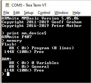 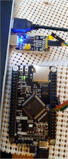 I put the benchmark.bas file on the SD card and ran it and got this: > run "benchmark.bas" Maximite Benchmark tests Benchmark 1 0.011 Benchmark 2 0.079 Benchmark 3 0.14 Benchmark 4 0.149 Benchmark 5 0.249 Benchmark 6 0.354 Benchmark 7 0.528 Benchmark 8 0.257 > So it works. I'll test further. It's a nifty little module--amazingly inexpensive for something this fast, with this many pins, and with an SD card. Once the fun dies down with the CMM2, I wonder it if might be possible to 1) update the latest firmware to use the serial console, 2) see about getting the normal flash to have the USB enumerated, 3) allow use of the full 1MB memory, and 4) recover the reserved pins for the display which isn't on this module. I will have a play with the TFT pins. It does have spi clock. The schematic has RS where the board has D/C. What it lacks is RESET, but I think a software reset is possible. Thanks, Volhout, for bringing this module up. Sorry you couldn't get yours running. Edited 2020-08-25 07:57 by lizby PicoMite, Armmite F4, SensorKits, MMBasic Hardware, Games, etc. on FOTS |
||||
| lizby Guru Joined: 17/05/2016 Location: United StatesPosts: 3696 |
I ran Paul_L's ta.bas benchmark from Is This Thing Fast Enough? and added it as F4mini: i5 celeron CMM2 MMX MMX ARMMITE ARMMITE MM+ MM+ MM2 5GHz 2GHz 252MHz 200MHz F4 F4mini 120MHz 100MHz Explore28 1 empty loop 266 844 1176 5109 6477 7083 7524 13532 16257 218620 2 read file 7047 19219 109740 170491 202206 190500 360407 491706 565035 3 write file 2891 8203 126305 189127 189466 221530 220821 325843 365102 4 mid$(x$) 1906 6125 24451 51147 64282 108169 101634 119408 143456 2402620 5 val(x$) 1391 4157 11555 26971 33824 51852 49796 70604 84823 1247490 I don't know what the speed is for either of the F4s. I added the Explore-28 MM2 speeds, omitting the file operations which aren't inherently available. Not too shabby for a $7 module. PicoMite, Armmite F4, SensorKits, MMBasic Hardware, Games, etc. on FOTS |
||||
| lizby Guru Joined: 17/05/2016 Location: United StatesPosts: 3696 |
Well, perplexing. I appear to have lost it. In fiddling with the ILI9341 I did OPTION LCDPANEL DISABLE and then set it to something which didn't work (nothing appeared on the screen (I had made an adapter)). I did a fair amount of other stuff on the device, including power cycles, and then tried to reset the TFT. This time, OPTION LCDPANEL DISABLE gave me "Error: invalid pin". So I decided to reflash and try again from the beginning--also with the serial console firmware. It flashed without a problem, but now I can't get the MMBasic splash and prompt, no matter how many RESETs or other stuff I try. I reflashed to the latest F4 firmware and got no USB, and reflashed again to the serial console version. No Joy. I don't know how I got lucky the first time, and I can't reproduce it. Too bad, because it was looking pretty good, and running fine with everything I tried. PicoMite, Armmite F4, SensorKits, MMBasic Hardware, Games, etc. on FOTS |
||||
| Volhout Guru Joined: 05/03/2018 Location: NetherlandsPosts: 5806 |
Strange, sounds a bit like my unit. I know accidents happen unexpected, but I did my experiments in a pretty well controlled environment (ESD mats and such), and still succeeded to fry the unit. Now you have similar strange behaviour. Maybe there is something wrong with these chips. or with the PCB itself. You may try to cool (fridge) the unit and power up. Or heat it and try. If that works you know the unit is unreliable, and unless you can find the problem (can also be in the silicon) you better throw it away. Volhout PicomiteVGA PETSCII ROBOTS |
||||
| lizby Guru Joined: 17/05/2016 Location: United StatesPosts: 3696 |
I flashed my second one of these with the serial console version. Works fine. I soldered two pins to a CR1220 battery holder and a 2-pin socket to B1, and the built-in RTC works. I had previously made a PCB to break out the F4 pins. There were no traces from one side to the other, so I just cut the center out of a blank one, soldered connectors, and plugged them in. As Volhout had noted, the pins are (almost) the same except that the power pins have been moved to the opposite end of the rows (and VR- and VR+ have gone away, but my PCB didn't use anything below them anyway). I used flying leads to provide 3V3 and 0V to where my board expected them. Now I have serial console out from my PCB, 6 DS18B20s being read on 1,4,5,16,17,18, and 4 LEDs flashing on 95,96,97,98. I'm afraid to try the ILI9341 again even though I won't repeat exactly what I did the first time (and I think I have a better idea of how to define the pins). What I did produced an error when I tried OPTION LCDPANEL DISABLE, but I still had the ">" prompt. When I reflashed, I couldn't get the prompt back. I don't understand how flashing the same MMBasic version a second time could have caused the module to stop working, but I'm worried to try on the module that is working now. On the other hand, these modules won't do anybody any good if they can't be reflashed. PicoMite, Armmite F4, SensorKits, MMBasic Hardware, Games, etc. on FOTS |
||||
| Volhout Guru Joined: 05/03/2018 Location: NetherlandsPosts: 5806 |
Hi lizby, Is there a date code on the chip ? Maybe these cheap chinees boards are manufactured using a batch ST dumped ? PicomiteVGA PETSCII ROBOTS |
||||
| lizby Guru Joined: 17/05/2016 Location: United StatesPosts: 3696 |
Here's what the chip looks like, but I don't know what it might tell me: 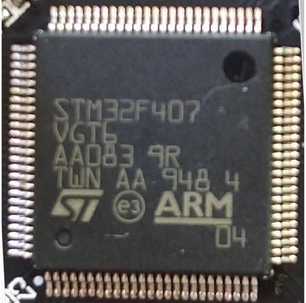 PicoMite, Armmite F4, SensorKits, MMBasic Hardware, Games, etc. on FOTS |
||||
| JohnS Guru Joined: 18/11/2011 Location: United KingdomPosts: 4281 |
Ouch - that's a VGT i.e. STM32F407VGT6 but the Armmite is for the VET6. Er, I haven't looked the differences up! John Edited 2020-08-28 03:59 by JohnS |
||||
| matherp Guru Joined: 11/12/2012 Location: United KingdomPosts: 11097 |
VG version is fine - just twice the FLASH. However there is something very suspicious about the pricing of these chips. Check this out and compare with a unit price of $10.51 from ST direct in volumes up to 500. The pricing of the VET board seems more possible - cheaper chip on a board that sells for more and made in huge volumes Edited 2020-08-28 04:20 by matherp |
||||
| lizby Guru Joined: 17/05/2016 Location: United StatesPosts: 3696 |
Interesting. 10 for 3 Pounds. But how does the F4 board we have been using sell for $9 if the STM32F4VET6 chip sells for over $10? It's too bad this doesn't "just work"--it's nice and compact, and aside from the issue with USB enumeration and possibly re-flashing, it seems to function with everything I've tried. PicoMite, Armmite F4, SensorKits, MMBasic Hardware, Games, etc. on FOTS |
||||
| JohnS Guru Joined: 18/11/2011 Location: United KingdomPosts: 4281 |
I think the CPUs are what were left after some production run. But they could be ones that failed some ST tests and then got smuggled out. (Add your own theory...) John |
||||
| Page 1 of 2 |
|||||
| The Back Shed's forum code is written, and hosted, in Australia. | © JAQ Software 2026 |
