
|
|
Forum Index : Microcontroller and PC projects : Relais controlled via Serial RS232
| Page 1 of 3 |
|||||
| Author | Message | ||||
| athlon1900 Regular Member Joined: 10/10/2019 Location: AustriaPosts: 49 |
Hello @all ! First i'm only a hobbyist in electronis.  But i'll share my relais project. The story : There are many relay cards to buy, but they all have one disadvantage. They are using too many pins. 1 pin per relay. Sure, there are I2C / SPI gpio extenders such as MCP23017, the control for beginners is a bit difficult. That's why I made a relay card with control via RS232. it is very easy to control, just send a string to the card to switch the relays. Fast, uncomplicated, only 1 pin! Since RS232 is used, an ESP8266 or ESP32 can also be used for control. It's easy with the esp-link firmware. I realized it with a Pic18F84A, which I still had lying around. If someone is interested, I can upload the hex file. best regards , athlon1900 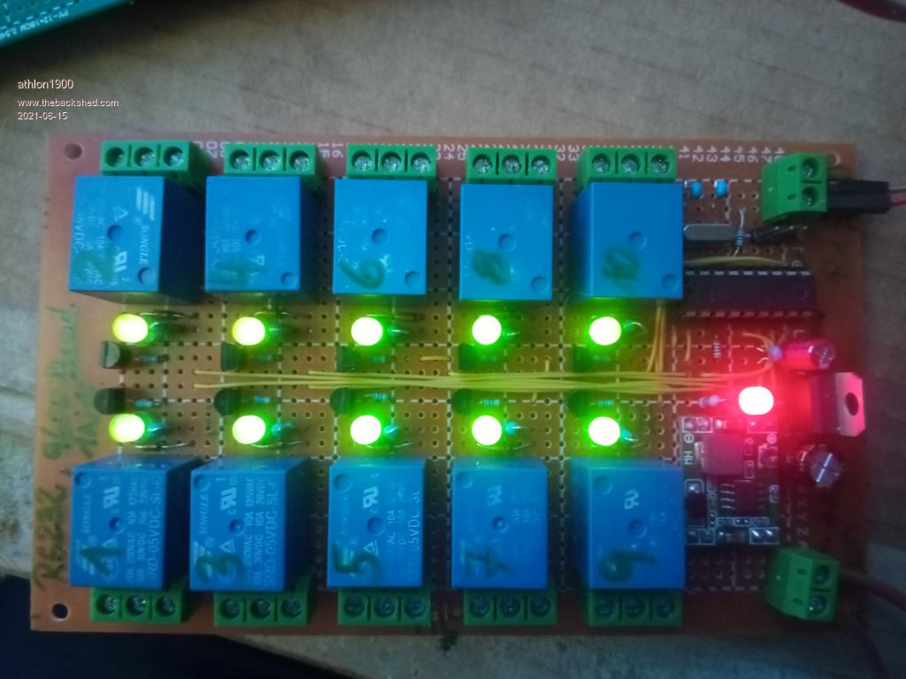 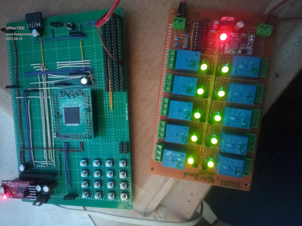 Edited 2021-06-15 20:45 by athlon1900 |
||||
| circuit Senior Member Joined: 10/01/2016 Location: United KingdomPosts: 299 |
This is a neat and interesting project, but I would highlight a pretty straightforward alternative for Micromite users - including beginners. In Geoff's manual "Getting Started with the Micromite" (Pages 70-73) there is a port extender based on a second Micromite running as a slave; this gives an additional 17 input-output pins that can be addressed within the Micromite Basic language; e.g. 'SPIN pin, output' and so forth. This works really well and all the code is there. The advantage of your project, however, is that you can add a radio link between the master and remote devices as you have highlighted. |
||||
| Mixtel90 Guru Joined: 05/10/2019 Location: United KingdomPosts: 8686 |
Very nice! Some good pictures too. I used to design electrical control panels and one of the arguments we used to get about relay circuits was what sort of contact monitoring is in use? It's not that unusual for relay contacts to weld shut. On normal control circuits it's rarely a problem - you're switching about 24v at 500mA with contacts rated at 5-10A, but on power circuits where ther may be inductive or capacitive loads it can be a real problem. Special safety relays are available that are usually used in pairs to monitor each other, giving a "healthy" signal if they both agree. An alternative that is sometimes used is a 3 or 4 pole relay with one contact used as a feedback to indicate the relay position (but it's not as good because a single contact can sometimes weld without the monitoring contact seeing it. You have the same problem if you monitor the relay current - it's dropped out but the circuit is still closed. A third way is to monitor the actual voltage on the switched output side of the contact. That works well, but you usually need opto-isolation and voltage dropping to do it - it gets complicated and isn't always possible. (I've used a similar approach for monitoring PLC outputs using inputs to make sure that they are switching correctly). Perhaps this is something you could consider sometime? Producing an input back to the controller to give confidence in the relay's operation? I'm not suggesting that you modify this system - it looks good! :) Mick Zilog Inside! nascom.info for Nascom & Gemini Preliminary MMBasic docs & my PCB designs |
||||
| Volhout Guru Joined: 05/03/2018 Location: NetherlandsPosts: 5807 |
Hi athlon1900, Nice project. How are you programming the PIC16F84A ? I used to program them via serial port programmers, but this is all history. After that I used PICKIT2 programmer, but PICKIT2 does not support eh F84 anymore. I know these chips are obsolete (there are newer replacements) but the old ones (still have some) ... how do you program them ?? Regards, Volhout PicomiteVGA PETSCII ROBOTS |
||||
| athlon1900 Regular Member Joined: 10/10/2019 Location: AustriaPosts: 49 |
Thanks Mixel90 for your praise My template for this project were the cheap relay cards. 1,2,4,8 channels, or whatever else there is. I like your thought , monitoring is a good idea. I won't change my circuit now, but I keep it in mind. Thanks , athlon1900 |
||||
| athlon1900 Regular Member Joined: 10/10/2019 Location: AustriaPosts: 49 |
thank you Volhout , I am glad that you like my project. I programmed the MCU with my TL866CS. With the "MiniPro" program it is easy to transfer a hex file to a Microchip PIC. Yes, I also built a serial port programmer once, but as you already mentioned, it was a long time ago. Those were times with IC-Prog and co.  A Pic16F818/819 can be used as a replacement and is pin compatible. I also built a 15 channel board with an optional ESP01 slot for a friend. This is based on a Pic16F819. (see image) best regards, athlon1900 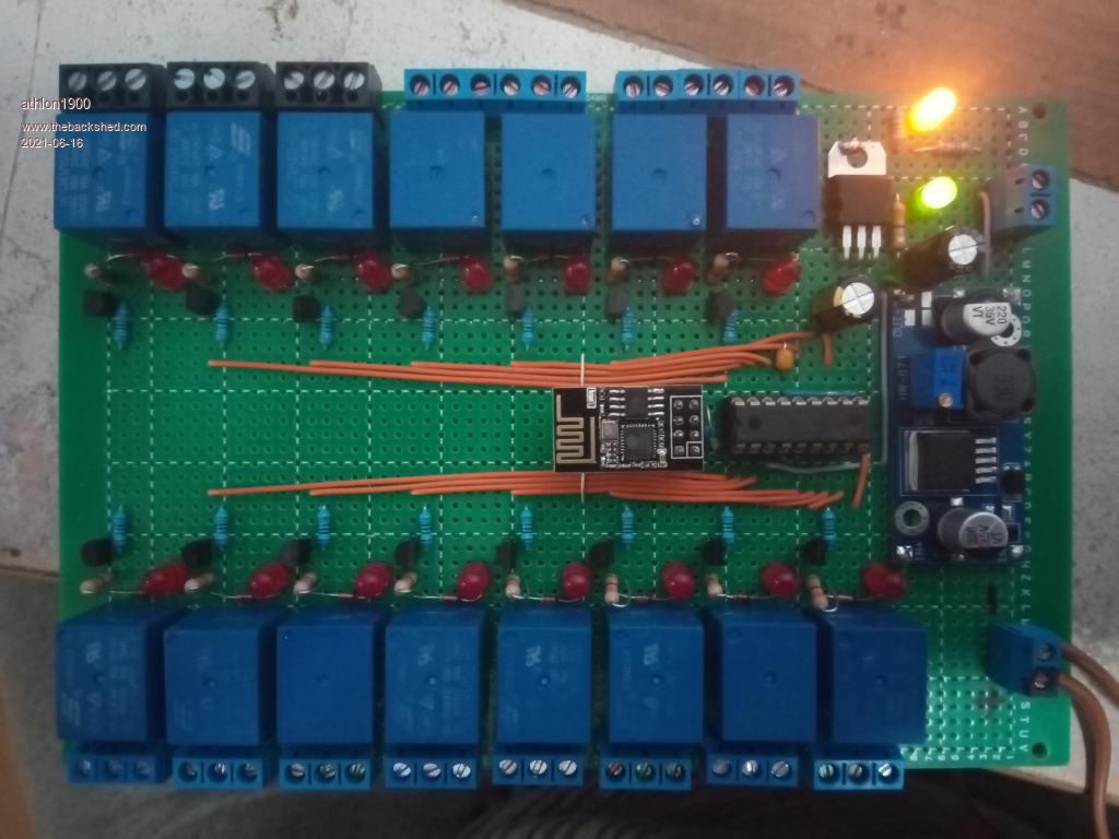 |
||||
| Volhout Guru Joined: 05/03/2018 Location: NetherlandsPosts: 5807 |
Yeah the cheapest way is to use a dual pole relay, end use the second contact as feedback. But there is sometimes a safety issue. Isolation between coil and contact is sometimes rated higher than between contacts. Feedback via optocouplers is not always practical. It is not simple to design a feedback circuit that can cope with all loads and voltages, AC and DC. Been there, done it.... Volhout PicomiteVGA PETSCII ROBOTS |
||||
| Mixtel90 Guru Joined: 05/10/2019 Location: United KingdomPosts: 8686 |
That's why I liked to use the little 4-pole relays, putting mains and monitoring on the two outside contacts. It was the best I could come up with at the time, although I suppose earthing the contact adjacent to the monitoring one would be a good idea. You can also get these relays as a 2-pole version which uses the two outside contact positions. Mick Zilog Inside! nascom.info for Nascom & Gemini Preliminary MMBasic docs & my PCB designs |
||||
| athlon1900 Regular Member Joined: 10/10/2019 Location: AustriaPosts: 49 |
Where did you buy these little relays , do you have a link ? |
||||
| Mixtel90 Guru Joined: 05/10/2019 Location: United KingdomPosts: 8686 |
there are several manufacturers make similar models - it's a pretty standard relay. Have a look for data on the Omron MY4 range. You'll probably find them or something similar at any of the big electronics suppliers - possibly some on ebay. Some are available with PCB pins, but you can also get PCB sockets and use plug-in relays with them. The MY4 has 1000v test voltage between contacts and 2000v for 1min from contacts to coil, so they are pretty good relays (not particularly cheap though). There are a lot of variations. Mick Zilog Inside! nascom.info for Nascom & Gemini Preliminary MMBasic docs & my PCB designs |
||||
| Volhout Guru Joined: 05/03/2018 Location: NetherlandsPosts: 5807 |
In europe we have safety standards that speak of 2 safety classes. Class 2: The equipment is grounded through safety ground (3'rd wire in your power cord) and all low voltage connections (like the USB port/RS232 port) are connected to it. Mostly you can only achieve class 2 with a metal housing. Safety test voltage is 2120Vdc Mechanical relays and optocouplers typically are rated 2500V. Class 1: The equipment is not connected to safety ground (2 wire power cord, or powered from a phone charger (*)). Most cases equipment in a plastic housing, but metal is definitely possible. In this case the test voltage is 4240Vdc. Mechanical relays and optocouplers are typically rated 5000V, or 3750V (**). Please be aware of such requirements if you design something for someone else. Whatever you do in your lab is up to you, but for others.... And the chineese dont get it....;) (***) Volhout (*) phone chargers typically have 2 pins, so class 1. But laptop power supplies typically have 3 pin. The 3rd pin is in many cases a functional ground pin, not a safety ground pin. The pin is mainly used for EMC requirements. (**) there are several standards, industrial, consumer etc... some have 4240Vdc, others have 3750Vdc. (***) the typical relay board you buy cheap from china has optocouplers driving the relays. The cheap relay is a primary safety barrier, the opto "could be "the second safety barrier. But they connect primary and secondary side of the optocoupler to the same power rail...why an optcoupler...? PicomiteVGA PETSCII ROBOTS |
||||
| Mixtel90 Guru Joined: 05/10/2019 Location: United KingdomPosts: 8686 |
The Chinese don't seem to get a lot of stuff - especially if safety makes it more expensive to produce. See Big Clive's comments on some of their "Class 1" CE marked "UL marked" USB chargers... Always treat Chinese relay and power supply boards with suspicion and don't use them for mains unless you are *certain* that electrical safety clearances have been met - especially on their PCBs. Watch relay voltage ratings. Sometimes they are quoted as AC, sometimes DC and sometimes a mix of both. :) It's generally the insulation resistance that is the most important factor in relays. 1000M at 500V, both coil-contact and contact-contact, is considered the safe minimum for 240vAC switching. Also, you aren't allowed to depend on a single device for mains isolation anyway. As a minimum there has to be an accessible, removable fuse or lockable isolating switch or breaker. Mick Zilog Inside! nascom.info for Nascom & Gemini Preliminary MMBasic docs & my PCB designs |
||||
| lizby Guru Joined: 17/05/2016 Location: United StatesPosts: 3703 |
What does the "M" stand for in "1000M" in this context? Is this independent of the mains circuit breaker? (Hmmm . . . How could it not be?) Do you mean like the inline switch on a floor lamp or a plug-in hanging light fixture? PicoMite, Armmite F4, SensorKits, MMBasic Hardware, Games, etc. on FOTS |
||||
| Mixtel90 Guru Joined: 05/10/2019 Location: United KingdomPosts: 8686 |
1000 MegaOhms - one of those lovely characters that make forums die. :) Basically, you can test it with a 500v Megger and get virtually no leakage whatsoever. For isolation I was thinking in the context of the control panels I used to design. The actual incoming cable to the panel might be live from a board some distance away that you don't have access to so local isolation is necessary. You always need *something* that can be used to disconnect the live side supply to a relay just in case the contacts weld and the load is going crazy. What it is doesn't matter much, but ideally a correctly rated fuse followed by a switch. The fuse protects both the switch and relay against short circuits on the load leading to high fault levels. Don't use a 32A fuse to feed a 5A rated relay. A short circuit load will probably vapourise the contact without blowing the fuse. :) In a domestic context there is a distribution board incoming switch then a fuse or breaker followed by a wall switch or socket & inline switch. Thus you can always isolate the socket even if the normal switch is welded closed. Mick Zilog Inside! nascom.info for Nascom & Gemini Preliminary MMBasic docs & my PCB designs |
||||
| lizby Guru Joined: 17/05/2016 Location: United StatesPosts: 3703 |
Thanks for that. High voltage stuff is black art to me, same as analog. Just curious, not going to make any 240V connections. PicoMite, Armmite F4, SensorKits, MMBasic Hardware, Games, etc. on FOTS |
||||
| Mixtel90 Guru Joined: 05/10/2019 Location: United KingdomPosts: 8686 |
240v is safe enough to play with as long as you take care, especially if it's only low current. To be safe allow 10mm of tracking distance on any surface between live and anything else. If you look at the base of a plug-in relay you'll see a moulded ridge that increases the tracking distance to something more than the straight line distance between the pins. PCBs are more difficult, you should cut a slot to get the clearance. Some of the cheap Chinese USB chargers that I mentioned earlier tend to "forget" that and, because there is insufficient tracking distance, rely on the pcb coating to insulate the outer shell of the USB connector from mains live... Mick Zilog Inside! nascom.info for Nascom & Gemini Preliminary MMBasic docs & my PCB designs |
||||
| athlon1900 Regular Member Joined: 10/10/2019 Location: AustriaPosts: 49 |
For the sake of completeness Here are my (dirty  ) schematic and the compiled hex-File. ) schematic and the compiled hex-File.Best regards and stay healthy , athlon1900 16F84A_SerialRelais_10-fach.zip 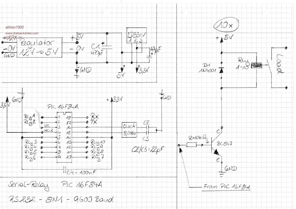 |
||||
| Volhout Guru Joined: 05/03/2018 Location: NetherlandsPosts: 5807 |
Any reason why you run the 16F84A at 3.3V (and 8MHz). The 16F84A's are fully capable of running at 5V. Actually, you may be lucky it works at all: There are 3 PIC16F84A's - the PIC16LF84A: runs from 2V to 5.5V, 4MHz max - The PIC16F84A-04: runs from 4V to 5.5V, 4 MHz max - The PIC16F84A-20: runs from 4.5 to 5.5V, 20MHz max. So you must use the PIC16F84A-20... 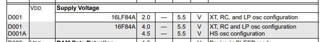 Running at 5V would also match better with the 10k base resistor on the BC547's. 10k would only allow for Ib=0.2mA, with a hfe of 100 (*), the BC547 can only drive 20mA for the relay coil. When the PIC runs at 5V you double the Ib. Volhout (*) BC547-C has higher hfe (current gain), but the generic BC547 has a wide range of hfe, with lower limit 100. Edited 2021-06-24 18:02 by Volhout PicomiteVGA PETSCII ROBOTS |
||||
| Mixtel90 Guru Joined: 05/10/2019 Location: United KingdomPosts: 8686 |
I'm guessing the 3.3v supply is to allow direct connection to a 'mite. If the supply voltage were to be increased to 5v a resistor of about 1k (I think I used 2k2 last time) could be put in series with TX signal to limit current into the RX pin of the 'mite. There are internal diodes from the inputs up to VCC which will clamp the input voltage to 3.3v, but you have to restrict the current or they die. Strictly speaking, this isn't RS-232 of course. It's logic level serial interfacing. "Proper" RS-232 isn't that easy to find outside industrial applications and old equipment now. Industry has mostly moved to versions of ethernet and RS485, but there is still legacy stuff around (but disappearing). Connect this board to a "proper" RS-232 port and the +/-12V will kill it. :) Personally, I'd like to see this changed to use the TX and RX pins for I2C. I think it would be more flexible nowadays and allow more expansion because of addressing. Also, I'm a bit evil and it would present athlon1900 with something of a chal1enge. ;) Edited 2021-06-24 18:24 by Mixtel90 Mick Zilog Inside! nascom.info for Nascom & Gemini Preliminary MMBasic docs & my PCB designs |
||||
| Volhout Guru Joined: 05/03/2018 Location: NetherlandsPosts: 5807 |
PIC16F84A has barely any peripherals. No UART, no I2C, no PWM, no ADC, no DAC, no SPI, only 1 timer. So everything must be done in SW. A SW UART is easy to do (up to 9600 baud) half duplex. But a SW I2C slave is not so obvious (not even at 100kHz). Volhout Edited 2021-06-24 19:07 by Volhout PicomiteVGA PETSCII ROBOTS |
||||
| Page 1 of 3 |
|||||
| The Back Shed's forum code is written, and hosted, in Australia. | © JAQ Software 2026 |
