
|
|
Forum Index : Microcontroller and PC projects : LCD + Pico combo
| Page 1 of 6 |
|||||
| Author | Message | ||||
| zeitfest Guru Joined: 31/07/2019 Location: AustraliaPosts: 662 |
LCD + touchscreen + Pico socket all in one combo , might be good (3.5 inch), I guess it's compatible to an extent at least |
||||
| Volhout Guru Joined: 05/03/2018 Location: NetherlandsPosts: 5806 |
Please watch out. Looking at the board rear side (all the individual buffers) , it is possible this is a configuration where the display is driven parallel. MMBasic only supports SPI connected displays on the pico. PicomiteVGA PETSCII ROBOTS |
||||
| matherp Guru Joined: 11/12/2012 Location: United KingdomPosts: 11097 |
Waveshare do a range of cards like this - see their site for the original docs. The issue is that the SDcard and display/touch use different pins for SPI whereas the PicoMite firmware, like all other versions, assumes that they will share an SPI channel. To support this card I would have to allow the SDcard to use an extra set of SPI pins which is inefficient but could be done. If there is real interest in this I could do it. Anyone want to send me one of the displays to develop on? |
||||
| Volhout Guru Joined: 05/03/2018 Location: NetherlandsPosts: 5806 |
The 2x 74hc4094 on that board seem to indicate (I could not download the circuit diagram, so I am not sure) the LCD is a parallel 16 bit LCD, and they use these logic chips to control it via serial. Not sure if this is the standard circuit used with the ILI9488 displays ? PicomiteVGA PETSCII ROBOTS |
||||
| lizby Guru Joined: 17/05/2016 Location: United StatesPosts: 3697 |
Looks compact if it could be made to work, but I could not see that any pins were brought out to headers. An output only device? PicoMite, Armmite F4, SensorKits, MMBasic Hardware, Games, etc. on FOTS |
||||
| Volhout Guru Joined: 05/03/2018 Location: NetherlandsPosts: 5806 |
Pretty sure they drive the ILI9488 in parallel mode, from external 74HC4094 shift registers. See the bundle of traces between the 74HC4094's and the LCD foil connector. 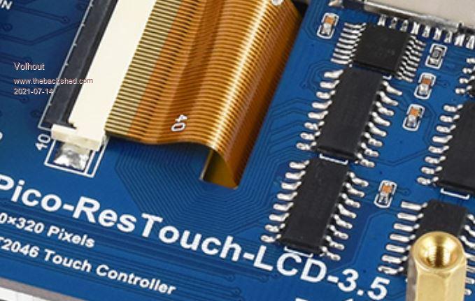 Maybe they use displays that are hard-wired to parallel mode (I have 1 example of ILI9341 that has the serial/parallel selection pin missing in the foil cable, so it can only be used in parallel mode ... Velleman VMA412 for Arduino UNO/MEGA). This means it may not be 100% compatible with ILI9488 in SPI mode (timing wise, or even logic wise). Yep, they do not output any of the 11 free GPIO pins on headers. As such not very usefull for a project, except when you solder directly to the Pi Pico. Edited 2021-07-14 21:44 by Volhout PicomiteVGA PETSCII ROBOTS |
||||
| Mixtel90 Guru Joined: 05/10/2019 Location: United KingdomPosts: 8682 |
Strangely enough, I was making a prototype pcb for a PicoMite LCD backpack same size as the original Micromite one, last night. PicoMite (intended to plug in) Reset button ILI9341 display hard wired - shares SPI with the SD card socket on the display Small RTC module hard wired ESP8266-01 (with it's own 3.3v reg) uses a small 4-wire multicore to connect it. A lot of pins are wired out: . a row for all 3 ADCs (including GND, VREF and +3v3) . a longer row for the rest (which includes the i2c pins used for the RTC and 3V3). There are pads to solder a 3V reference in position and link 3V-EN low. The 5V supply on board can be taken from either VBUS or VSYS. PCB is single-sided with 10 wire links. :) Everything except the ESP fits within the outline of the display PCB. Unfortunately the paper I used for toner transfer is pretty bad and not all the toner decided not to stay on the board. It might be ok for a prototype though as it only effects the SD card access & I can bodge the connections. Edit: I forgot the 12mm speaker with biased-off driver mosfet, gate wired to a pin that can be wire linked to somewhere if you want to use it. :) I also forgot the 5V input terminals for use stand-alone without a USB connection. Edited 2021-07-14 22:35 by Mixtel90 Mick Zilog Inside! nascom.info for Nascom & Gemini Preliminary MMBasic docs & my PCB designs |
||||
| lizby Guru Joined: 17/05/2016 Location: United StatesPosts: 3697 |
Much more useful than the commercial one. What did you do the design with? Can you post pics and files when convenient and updated to suit you? PicoMite, Armmite F4, SensorKits, MMBasic Hardware, Games, etc. on FOTS |
||||
| Mixtel90 Guru Joined: 05/10/2019 Location: United KingdomPosts: 8682 |
It's all drawn in nanoCAD as a *.DWG file. At the moment anyway. :) It'll be easy enough to export as full-size track patterns in a pdf. It might be better to see if it works first though - just in case I messed up *really* badly. lol Mick Zilog Inside! nascom.info for Nascom & Gemini Preliminary MMBasic docs & my PCB designs |
||||
| Mixtel90 Guru Joined: 05/10/2019 Location: United KingdomPosts: 8682 |
Oh, go on then. Confession time ... I did mess it up and did the transfer in reverse so I'll be redoing it. lol Here's what I'm aiming for anyway: PicoMite Backpack 001.pdf ** Don't use this pcb printout directly as it probably won't print out to scale without some messing about ** Mick Zilog Inside! nascom.info for Nascom & Gemini Preliminary MMBasic docs & my PCB designs |
||||
| lizby Guru Joined: 17/05/2016 Location: United StatesPosts: 3697 |
LOL. These days, it seems, if there's a right way and a wrong way to orient something, there's little better than a 50-50 chance I'll get it the right way. Today I was saved by the designer of the little solar charger I'm testing having put in a diode to prevent harm from reversing 12V and 0V. Nice work though. Second time's a charm. ~ Edited 2021-07-15 06:07 by lizby PicoMite, Armmite F4, SensorKits, MMBasic Hardware, Games, etc. on FOTS |
||||
| Volhout Guru Joined: 05/03/2018 Location: NetherlandsPosts: 5806 |
@Mixtel: nice design. Assuming you connect the buzzer to a PWM output of the pico. If you do, it is possible to use the 2 buzzer holes for B and E of a 2N2907, and connect the C to the LED resistor. Dimming backlight option if buzzer not needed. I like this board. Very much in Backpack style, but better (SD card, more IO). There is 1 improvement if I may suggest. Your IO header is 19 pins. Could you add pin 20, carrying +5V. Sometimes handy to have a raw voltage to create local power at the other side of the cable. I am sure you are offering PCB's .... can I order one ? Edited 2021-07-15 17:01 by Volhout PicomiteVGA PETSCII ROBOTS |
||||
| Mixtel90 Guru Joined: 05/10/2019 Location: United KingdomPosts: 8682 |
Those mods have cost you two (yes - Two!) more wire links. :) That does have the advantage though that the link to the 5V pin can be omitted for safety if required. Yep, I managed to fit them on but you need to be creative in bending transistor leads to get it to fit. I'd like to have kept both the speaker and PWM backlight, but there's only so much you can do with a board designed for DIY manufacture. I wasn't really thinking of doing boards originally, it was very much a "just for fun" project, but if people are interested I'll think again on that. :) Edit: ** DRAT! ** Just realised that the backpack can't have sockets for the display unless I make it double-sided. Doesn't necessarily have to be PTH but it's messy otherwise. Awkward for DIY. All because the display sockets are mounted on the copper side. At one point I did try an arrangement with the PicoMite between the display and the PCB but it didn't work well and I never completed it. Still, I suppose it encourages me to transfer the design to Eagle and get PCBs made elsewhere. Or find some SMD SIL sockets. :) . Edited 2021-07-15 21:34 by Mixtel90 Mick Zilog Inside! nascom.info for Nascom & Gemini Preliminary MMBasic docs & my PCB designs |
||||
| lizby Guru Joined: 17/05/2016 Location: United StatesPosts: 3697 |
Long-lead female header pins can be lifted above the copper side about an eighth of an inch so that they can be soldered. Raises the LCD a little, but shouldn't matter too much in most cases. On this picomite perfboard, I didn't raise the header for that reason, but it shows the principle.  PicoMite, Armmite F4, SensorKits, MMBasic Hardware, Games, etc. on FOTS |
||||
| Mixtel90 Guru Joined: 05/10/2019 Location: United KingdomPosts: 8682 |
True. In the past I've also bent alternate pins out at right-angles. Almost like a proper SMD header, in fact. That's probably what I'll do at first. If I get boards made they'll be double sided PTH as it's the same price (IIRC) as single-sided. I can get rid of the links then too. Mick Zilog Inside! nascom.info for Nascom & Gemini Preliminary MMBasic docs & my PCB designs |
||||
| vegipete Guru Joined: 29/01/2013 Location: CanadaPosts: 1167 |
PDF above PCBified: WARNING: ABSOLUTELY NO VERIFICATION PERFORMED! I can provide Gerbers and edits if required. 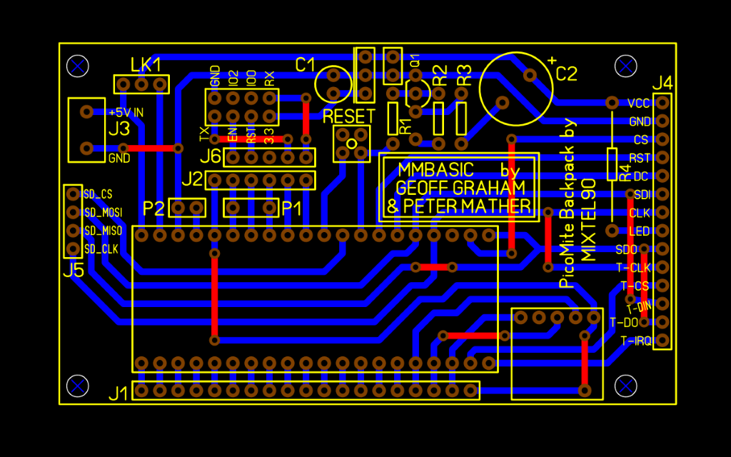 Edited 2021-07-16 04:08 by vegipete Visit Vegipete's *Mite Library for cool programs. |
||||
| Mixtel90 Guru Joined: 05/10/2019 Location: United KingdomPosts: 8682 |
Very nice, Pete - now you only need the version with Volhout's mods (+ a bit) . ;) PicoMite Backpack 001a.pdf I *think* the track layout matches the circuit ok. I've not shown the rotation of the transistor for the mod - the flat is to the RHS. Edit: Forget the above. This version has the component refs on it. Note that the caps are not as shown on your version, Pete. C1 is a little ceramic, C2 is a 2.2uF electrolytic. X1 is the 12mm speaker. @anyone Incidentally, is GUI BEEP implemented on the PicoMite? If so, does it use a normal pin or a PWM? Edited 2021-07-16 06:02 by Mixtel90 Mick Zilog Inside! nascom.info for Nascom & Gemini Preliminary MMBasic docs & my PCB designs |
||||
| vegipete Guru Joined: 29/01/2013 Location: CanadaPosts: 1167 |
Changes added, I think. I also checked that the LCD pin dimensions are correct, and changed the reset button to a 'normal' Omron B3F. 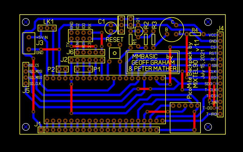 Visit Vegipete's *Mite Library for cool programs. |
||||
| Mixtel90 Guru Joined: 05/10/2019 Location: United KingdomPosts: 8682 |
hehe - crossover... PicoMite Backpack A1.pdf That's looking very nice... :) OOPS - I've put C2 wrong polarity. It should be +ve to the reg output. I got the reg wrong way round too. It should have the tab to the right. . Edited 2021-07-16 06:31 by Mixtel90 Mick Zilog Inside! nascom.info for Nascom & Gemini Preliminary MMBasic docs & my PCB designs |
||||
| Mixtel90 Guru Joined: 05/10/2019 Location: United KingdomPosts: 8682 |
Thanks, Pete. :) I've gone over all the tracks now and they fit the circuit. Connections to the ESP, RTC and display seem right. I like what you did with R4. :) Note that the speaker is 12mm dia. If you have difficulty at that size then R4 could probably be vertically aligned. If you could update as follows, please, I think we're ready to roll with a PCB order. The little cap next to Q1 is C1 What you've shown as C1 is C2, with + to the bottom. The tab on the reg should be on the RHS. There's a single pin just at the base of the R in R1 (above the second M in MMBasic), which is the input pin J7 to R2. Mick Zilog Inside! nascom.info for Nascom & Gemini Preliminary MMBasic docs & my PCB designs |
||||
| Page 1 of 6 |
|||||
| The Back Shed's forum code is written, and hosted, in Australia. | © JAQ Software 2026 |
