
|
|
Forum Index : Microcontroller and PC projects : Flash 3 common catode LED lamps.
| Page 1 of 12 |
|||||
| Author | Message | ||||
| bob.steel Senior Member Joined: 27/02/2020 Location: AustraliaPosts: 188 |
Flash 3 common catode LED lamps. I hope this is permissable as my focus has changed to using a microcontroller. This is a follow on from a thread in Electronics https://www.thebackshed.com/forum/ViewTopic.php?FID=4&TID=13842 I have an arduino 5 v signal coming into a N channel Mosfet Using a IRF520 Mosfet C=783pF , Vt=3.6 v , I have its Gate driven by a 5 volt output signal from the Arduino through a voltage divider of 470 Ohms signal side and 10 K on the 28 volt negative .Common ground wire. Atm The light stays permanently on when full voltage is applied to the Light anodes on the positive with Mosfet under and source connected to ground. Reducing the 28 volt supply down to about 8-9 volts brings the signal through and flashes the lights but it is no good to me down there and I'm driving 2 lights atm both flash on each signal instead of them flashing individually. Can anyone tell me why it would be doing that ? Is it bleeding current through the internal diode perhaps. I don't understand that. So I am trying to drive 3 separate LED lights ,current limited , with 3 of 5 v signals coming off 3 pins of the arduino. Can this be done? 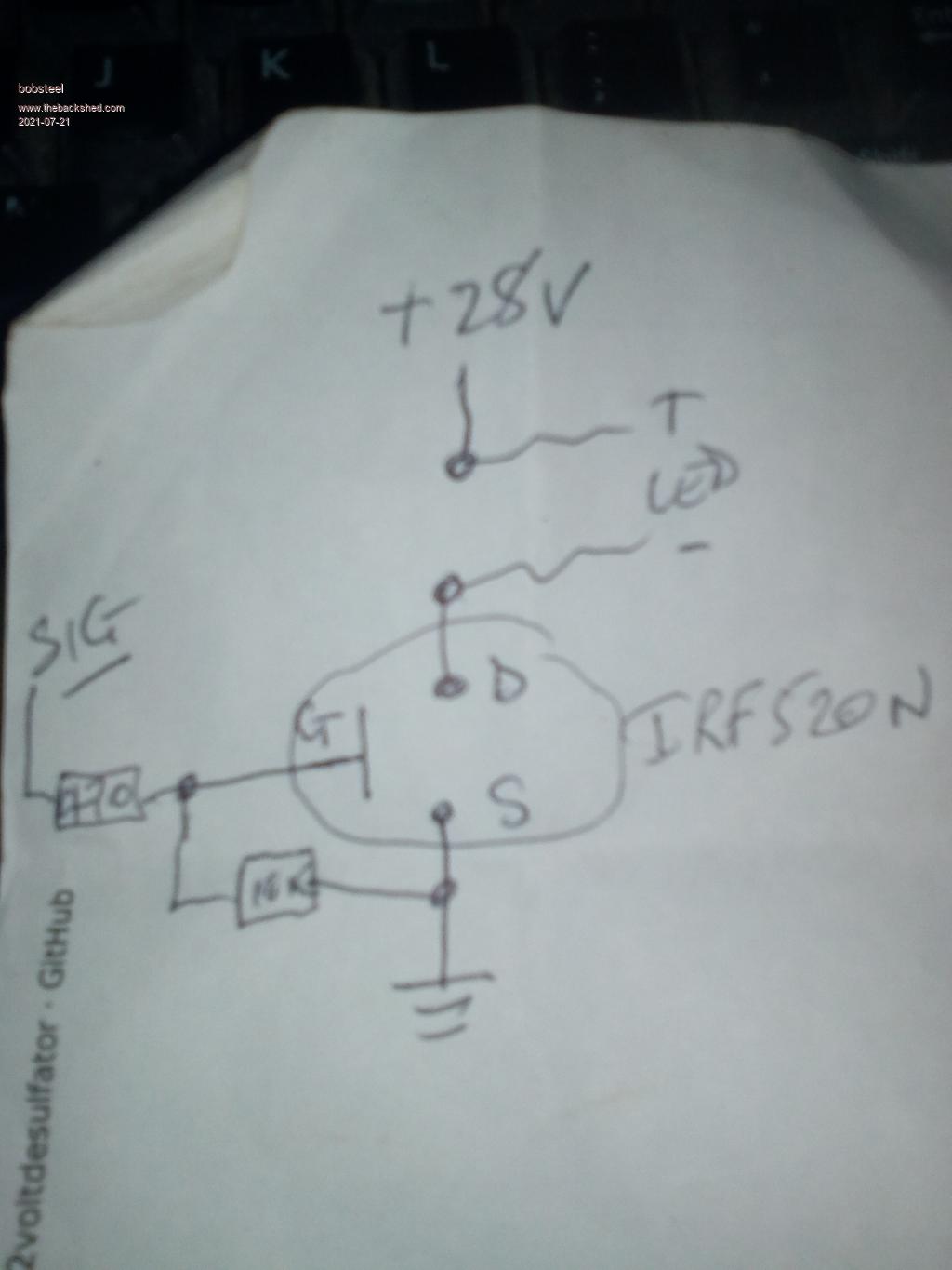 Edited 2021-07-21 13:06 by bob.steel |
||||
| Turbo46 Guru Joined: 24/12/2017 Location: AustraliaPosts: 1693 |
FETs aren't my thing - easy to do with transistors. But: I had a brief look at your other post and it appears that you have two common cathode LEDs so you will need two high side drivers to drive each anode circuit separately and connect the cathodes to zero volts. It may need a couple of transistors or FETs to level shift the drive signal for each high side driver. I don't know what is limiting the current for the LEDs internally but it's probably not a simple resistor so there may be leakage in there that is causing the other LED to come on. I'm suspecting that gate voltage is not high enough to turn the FET off at 28 volts until you lower the supply voltage. Transistor circuit 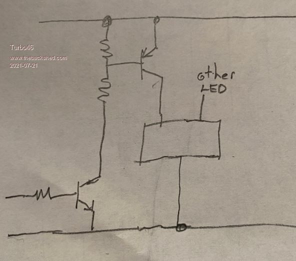 You may need this sort of circuit to drive the FET if you want to use it. Bill Keep safe. Live long and prosper. |
||||
| Turbo46 Guru Joined: 24/12/2017 Location: AustraliaPosts: 1693 |
A bit of checking suggests that you can't use an N channel MOSFET as a high side switch because you need a gate voltage higher than the drain voltage to turn in on. The drain voltage will be 28 volts when it is off. Unless you have a way of providing a higher voltage than the 28 volts that is. Bill Keep safe. Live long and prosper. |
||||
| Mixtel90 Guru Joined: 05/10/2019 Location: United KingdomPosts: 8911 |
Sometimes you have to think out of the box, Bob. Use the KISS principal. You want to switch a max of 450mA at 28vDC. The lights are unnecessary during the day - you probably won't be able to see them in daylight. So they aren't running 24/7. The flash rate is low. Use relays. The load is well within the rating of even small pcb relays. 1A/30VDC would be plenty. There's virtually no voltage drop. The load seem sensible (just test for inrush first) so the contact rating will probably be very close to what it says on the box. You'll probably wear the relays out mechanically before the contacts suffer. If you need to replace them after 20 years does it matter? Use a microcontroller or PicoMite with driver transistors (2k2 resistor from controller output to transistor base. Use a diode across the relay coil) to power the relays and you can have any flash sequence you like. Edited 2021-07-21 17:18 by Mixtel90 Mick Zilog Inside! nascom.info for Nascom & Gemini Preliminary MMBasic docs & my PCB designs |
||||
| bob.steel Senior Member Joined: 27/02/2020 Location: AustraliaPosts: 188 |
Actuslly i should have said the white light pulls about 900mA and the blue 100mA . If I add a red it will be about 100nA too. The lights are movement sensor controlled and that only gets switched on at night. Thanks will study whats come back a while. Edited 2021-07-21 19:24 by bob.steel |
||||
| Tinine Guru Joined: 30/03/2016 Location: United KingdomPosts: 1646 |
This any good? Channels can be paralleled 2981 current source.pdf Craig |
||||
| Volhout Guru Joined: 05/03/2018 Location: NetherlandsPosts: 5931 |
Common cathode LED lamps can be driver directly from PLC outputs. The typical 24V PLC output has a P-FET or PNP transistor pulling the output to it's 24V line. These circuits are directly usable at 28.8V also (PLC's often have a spec up to 30Vdc). IN essence Turgo46's circuit will work. For 450mA (white LED) you will need roughly 2.2k resistors in all 3 locations. The input transistor can be a BC548 or similar, the output transistor a BD140 or beefier. Example of a PLC output circuit (using optocouplers to isolate the power circuit from the digital circuit. 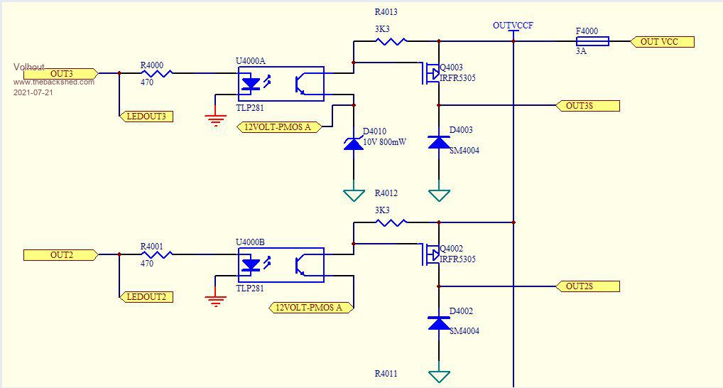 PicomiteVGA PETSCII ROBOTS |
||||
| CaptainBoing Guru Joined: 07/09/2016 Location: United KingdomPosts: 2171 |
hmmm... that is odd. Looking at the datasheet there is nothing that leaps out that might be responsible. One thing I note people do is a series resistor with the gate - I suspect a hangover from bipolar requirements. That 470R, get rid of it. The gate is insulated from the rest of the internals, many megohms. You can turn on a MOSFET like this by tapping the gate with your voltage and then to turn it off, tap again with GND - but it might begin to turn on again just from the charge in the air (watch those transition times) - I demonstrate this phenomenon here. Your arduino is likely to exceed the absolute max VGSth of 4V as an output. Incidentally that video is almost precisely what you are doing, I split the LED strings into two because of the PSU capabilities but it is still acting as a low side switch and eventually got PWM pulses to control the intensity of the LEDs in an Aquarium light controller I built... still working fault free years later. The 10K to ground is only necessary if you are driving from a "slow" hi-impedance line (e.g. an IO pin that is input by default). tbh, your arduino will boot that quickly you probably wouldn't see any flicker of the LEDs if it were to happen anyway, but what the heck, leave it there just to ground the gate while your prog wakes up. One thing I would say... the IRF520 is an older device with a fairly high RDSon of 0.2R You will likely need to heatsink it. I use a lot of IRLB3034 which have a typical RDSon of 0.015R. I used one to flick the heaters on in my bed plate heater; 27V@4.4A, it doesn't even get warm (I2R gives 290mW dissipation). keen to hear how you get on Edited 2021-07-21 22:19 by CaptainBoing |
||||
| Volhout Guru Joined: 05/03/2018 Location: NetherlandsPosts: 5931 |
The IRF520 is a nice FET, but it needs a nice gate drive voltage. 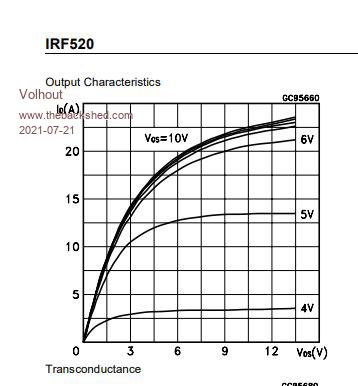 This shows the FET will not turn on fully when the gate voltage is 4V or lower. It needs minimal 5V, but preferably 6V or more. So you can not drive it with 3.3V from a mite. You need special "logic voltage" FET's, or a driver transistor and higher voltage. Volhout Edited 2021-07-21 23:43 by Volhout PicomiteVGA PETSCII ROBOTS |
||||
| Mixtel90 Guru Joined: 05/10/2019 Location: United KingdomPosts: 8911 |
Th whole point is that Bob has buckets of IRF520 and no P-channel at all. Unfortunately he probably has the most unsuitable device you can get your hands on to drive common cathode LEDs. :) An approach I haven't seen mentioned is to use an auxiliary supply, possibly from a 9 battery, on top of the 28v supply. Use that to turn on the mosfet in source follower mode. The turn on resistor would need to be high to avoid draining the battery too fast when the mosfet is turned off. Mosfets are voltage operated, gate current is minimal so the resistor can be pretty high. Cap'n - the gate resistor is to help damp very high frequency parasitic oscillation caused by the LC network consisting of the connecting wire and gate capacitance. It's not always strictly necessary but the cost is negligible. It would cost far more to add it later if you find the mosfet is running very hot with a relatively low load. A typical pcb relay rated at (resistive) 3A 120V Tianbo HJR4102-D-24V-S-Z costs 62p and will probably run for well over 10 years. It has a 24v 1600R 15mA coil so a small series resistor could be used to keep coil dissipation down if that bothers anyone (it will stand 30v anyway). All it needs is the driver transistor that you'd need for a mosfet, a base resistor and a coil diode. It doesn't load the 5V supply. No heatsink needed. You can skip the base resistor if you use a mosfet like the 2N7000 to drive the relay rather than a normal transistor. Mechanical life expectancy is 10,000,000 operations at 300 operations per min. There's nothing wrong with old-school tech sometimes. Of course, it might click a bit. :) This could be built with a 6-pin PIC chip, 3 off 2N7000, 3 relays 3 diodes, a 78L05 to power the pic and a couple of caps. Of course, you'd need to program the pic - and you'd still have a spare pin. For a light sensor? Edited 2021-07-22 01:46 by Mixtel90 Mick Zilog Inside! nascom.info for Nascom & Gemini Preliminary MMBasic docs & my PCB designs |
||||
| Tinine Guru Joined: 30/03/2016 Location: United KingdomPosts: 1646 |
Ah, that explains it. I am only on my phone and I was beginning to think that I'd missed the Heath Robinson / Rube Goldberg stipulation.  |
||||
| Turbo46 Guru Joined: 24/12/2017 Location: AustraliaPosts: 1693 |
I did suggest that a higher voltage would be needed to operate the MOSFET in my second post. How far do you want to go to use unsuitable obsolete components just because you already have them? Volhout's component suggestions might be OK but the BD140 is a darlington transistor and the Vce saturation voltage is therefore higher than I would like at 2 volts. It is also an NPN and not PNP. I would use something like a TIP30 and drive it harder. I still believe that the circuit I presented is the simplest required to do the job. Bill Keep safe. Live long and prosper. |
||||
| CaptainBoing Guru Joined: 07/09/2016 Location: United KingdomPosts: 2171 |
I must be missing something. Why all the talk of hi-side switching? In his photo, the load is north of the mosfet with a grounded source. That is low-side. N-MOSFETs are an ideal solution here, done it myself many times. what have I missed?  |
||||
| Turbo46 Guru Joined: 24/12/2017 Location: AustraliaPosts: 1693 |
Common catode (sic) LED lamps. Keep safe. Live long and prosper. |
||||
| Mixtel90 Guru Joined: 05/10/2019 Location: United KingdomPosts: 8911 |
it's a 3-wire led spotlight, apparently, in white and blue, with a common cathode. It includes current limiting and the working voltage is specified as 24v IIRC. PMOS high side switching would be ideal but he hasn't got them. I'm afraid that any messing about with the IRF520 is probably a waste of time and effort. Money spent on bits to get them to work would probably be far better spent on some new P-channel FETS or relays. Mick Zilog Inside! nascom.info for Nascom & Gemini Preliminary MMBasic docs & my PCB designs |
||||
| CaptainBoing Guru Joined: 07/09/2016 Location: United KingdomPosts: 2171 |
ah right - I went purely from the circuit in the photo. no, in that case his circuit as drawn won't work. Needs an artificial high voltage for the gate or a bootstrap like this Edited 2021-07-22 07:30 by CaptainBoing |
||||
| bob.steel Senior Member Joined: 27/02/2020 Location: AustraliaPosts: 188 |
Trying to make sense of this? 28 volts in on vcc I guess and green triangles are ground but the optos have a different ground. Input micro signals in on the left. What the heck is all the rest? Where can I learn what all that means ? There is a 12 volt input and a zener on one gate but not the other. seven outs ,an R4013 and R4012 but no R4011? F4000 Im guessing is a fuse? Quite confusing at first sight sorry. Is this perhaps dealing with electrons coming in on the negative and out on the positive? Edited 2021-07-22 08:17 by bob.steel |
||||
| Solar Mike Guru Joined: 08/02/2015 Location: New ZealandPosts: 1214 |
There are chips that generate their own gate bias voltage from the internal opto IR led, I would use one of these Si8752 to drive the high side mosfet, they output 10v so will work with any common device; as used in SSD relays or other slow switching devices. I use them in PV charge controllers. Mike |
||||
| bob.steel Senior Member Joined: 27/02/2020 Location: AustraliaPosts: 188 |
Happy days to you too. Not seen that done so interesting video thanks. |
||||
| phil99 Guru Joined: 11/02/2018 Location: AustraliaPosts: 3293 |
To avoid further duplication it may be of help if everyone reads the original thread in the electronics section. |
||||
| Page 1 of 12 |
|||||
| The Back Shed's forum code is written, and hosted, in Australia. | © JAQ Software 2026 |
