
|
|
Forum Index : Microcontroller and PC projects : VGAMite V5.07.00 alpha releases
| Page 1 of 5 |
|||||
| Author | Message | ||||
| matherp Guru Joined: 11/12/2012 Location: United KingdomPosts: 11100 |
Please find attached the first alpha release of the VGAMite based on the STM32F411 "Blackpill" 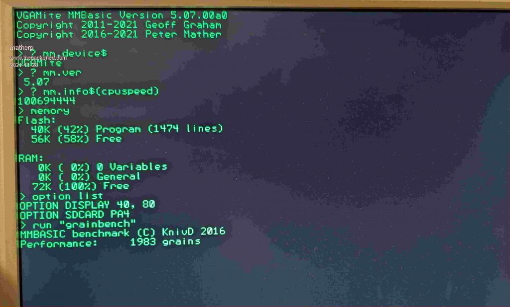 411VGAV5.07.00a0.zip This supports a full implmentation of MMBasic and the usual peripherals and I/O 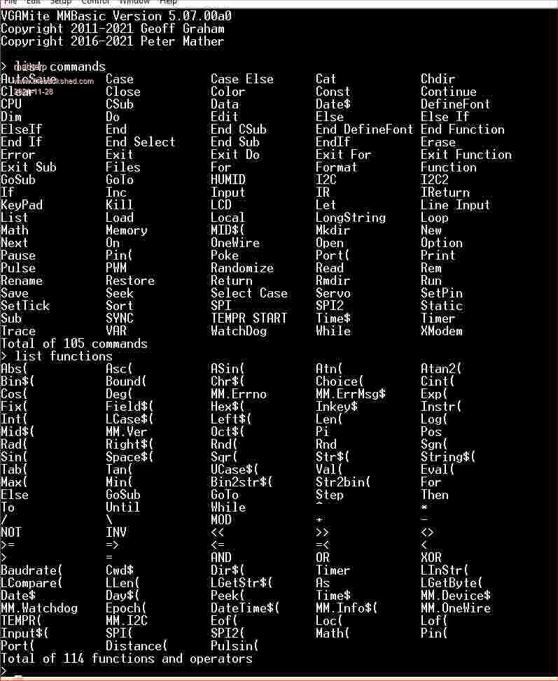 Current status is as follows: VGA output and MMBasic operation including editor - tested VGA support is 640x480 @ 60Hz using a 25.175MHz pixel clock Font is currently 8x12 pixels giving 80 characters across with 40 lines SDcard support - tested I2C and I2C2 - tested SPI and SPI2 - tested (NB: SPI2 not available if SDcard enabled) PS2 keyboard - tested XModem support including transfer to and from SDcard - tested COM1 and COM2 - tested TEMPR command and function - tested SETPIN DIN, DOUT, AIN - tested but not every pin SETPIN FIN, CIN, PER - implemented but untested IR, PULSE, PULSEIN, KEYPAD, LCD, DISTANCE, PORT, HUMID - implemented but untested MATH routines as per CMM2 - implemented but untested Graphics commands, variable font support - to be implemented Flash support, GPS support and background ADC support TBD WS2812 support cannot be implemented due to timing conflicts with the VGA output NB: THis is an alpha release. Although functionality has been tested where stated it has not been regression tested as new functionality was added so expect bugs Pinout { GPIOB, GPIO_PIN_12, DIGITAL_IN | DIGITAL_OUT , 0}, // pin 1 KEYBOARD_DATA { GPIOB, GPIO_PIN_13, DIGITAL_IN | DIGITAL_OUT , 0}, // pin 2 SPI_CLK { GPIOB, GPIO_PIN_14, DIGITAL_IN | DIGITAL_OUT , 0}, // pin 3 SPI_IN { GPIOB, GPIO_PIN_15, DIGITAL_IN | DIGITAL_OUT , 0}, // pin 4 SPI_OUT { NULL, 0, PUNUSED , 0}, // pin 5 A8: VGA_HSYNCH { NULL, 0, PUNUSED , 0}, // pin 6 A9: CONSOLE_TX { NULL, 0, PUNUSED , 0}, // pin 7 A10: CONSOLE_RX { GPIOA, GPIO_PIN_11, DIGITAL_IN | DIGITAL_OUT , 0}, // pin 8 COM2_TX { GPIOA, GPIO_PIN_12, DIGITAL_IN | DIGITAL_OUT , 0}, // pin 9 COM2_RX { NULL, 0, PUNUSED , 0}, // pin 10 A15: VGA_VSYNCH { GPIOB, GPIO_PIN_3, DIGITAL_IN | DIGITAL_OUT , 0}, // pin 11 I2C2_SDA { GPIOB, GPIO_PIN_4, DIGITAL_IN | DIGITAL_OUT , 0}, // pin 12 PWM1A { NULL, 0, PUNUSED , 0}, // pin 13 B5: VGA_OUTPUT { GPIOB, GPIO_PIN_6, DIGITAL_IN | DIGITAL_OUT , 0}, // pin 14 PWM2A { GPIOB, GPIO_PIN_7, DIGITAL_IN | DIGITAL_OUT , 0}, // pin 15 PWM2B { GPIOB, GPIO_PIN_8, DIGITAL_IN | DIGITAL_OUT , 0}, // pin 16 I2C_SCL { GPIOB, GPIO_PIN_9, DIGITAL_IN | DIGITAL_OUT , 0}, // pin 17 I2C_SDA { NULL, 0, PUNUSED , 0}, // pin 18 5V { NULL, 0, PUNUSED , 0}, // pin 19 GND { NULL, 0, PUNUSED , 0}, // pin 20 3V3 { NULL, 0, PUNUSED , 0}, // pin 21 VBAT { GPIOC, GPIO_PIN_13, DIGITAL_IN | DIGITAL_OUT , 0}, // pin 22 GREN LED { NULL, 0, PUNUSED , 0}, // pin 23 C14: OSC32_IN { NULL, 0, PUNUSED , 0}, // pin 24 C15: OSC32_OUT { NULL, 0, PUNUSED , 0}, // pin 25 RESET { GPIOA, GPIO_PIN_0, DIGITAL_IN | DIGITAL_OUT | ANALOG_IN , ADC_CHANNEL_0}, // pin 26 KEY/WAKEUP/COUNT/IR { GPIOA, GPIO_PIN_1, DIGITAL_IN | DIGITAL_OUT | ANALOG_IN , ADC_CHANNEL_1}, // pin 27 COUNT { GPIOA, GPIO_PIN_2, DIGITAL_IN | DIGITAL_OUT | ANALOG_IN , ADC_CHANNEL_2}, // pin 28 COM1_TX { GPIOA, GPIO_PIN_3, DIGITAL_IN | DIGITAL_OUT | ANALOG_IN , ADC_CHANNEL_3}, // pin 29 COM1_RX { GPIOA, GPIO_PIN_4, DIGITAL_IN | DIGITAL_OUT | ANALOG_IN , ADC_CHANNEL_4}, // pin 30 { GPIOA, GPIO_PIN_5, DIGITAL_IN | DIGITAL_OUT | ANALOG_IN , ADC_CHANNEL_5}, // pin 31 SPI2_CLK/SD_CLK { GPIOA, GPIO_PIN_6, DIGITAL_IN | DIGITAL_OUT | ANALOG_IN , ADC_CHANNEL_6}, // pin 32 SPI2_IN/SD_IN { GPIOA, GPIO_PIN_7, DIGITAL_IN | DIGITAL_OUT | ANALOG_IN , ADC_CHANNEL_7}, // pin 33 SPI2_OUT/SD_OUT { GPIOB, GPIO_PIN_0, DIGITAL_IN | DIGITAL_OUT | ANALOG_IN , ADC_CHANNEL_8}, // pin 34 PWM1B { GPIOB, GPIO_PIN_1, DIGITAL_IN | DIGITAL_OUT | ANALOG_IN , ADC_CHANNEL_9}, // pin 35 PWM1C { GPIOB, GPIO_PIN_2, DIGITAL_IN | DIGITAL_OUT , 0}, // pin 36 KEYBOARD_CLOCK { GPIOB, GPIO_PIN_10, DIGITAL_IN | DIGITAL_OUT , 0}, // pin 37 I2C2_SCL { NULL, 0, PUNUSED , 0}, // pin 38 3V3 { NULL, 0, PUNUSED , 0}, // pin 39 GND { NULL, 0, PUNUSED , 0}, // pin 40 5V To enable the SDcard connect the SPI pins to PA5,PA6, and PA7. Then issue OPTION SDCARD pinno where pinno is the pin connected to the CS pin of the SDcard or DISABLE To enable the PS2 keyboard use OPTION KEYBOARD type Type can be one of US, UK, GR, IT, BE, FR, ES, or DISABLE (default) Note in all case pin numbers can be either the number on the module (1-40) or the pin designation e.g. PB10. The pin numbering of the module should be obvious from the table above. To connect the VGA connect VGA pins 5,6,7,8,9,and 10 to GND. Connect VGA pin 13 to PA8. Connect VGA pin 14 to PA15. Connect VGA pin 2 to PB5 using a 120ohm resistor. Also Connect VGA pin 2 to the anode of a 1n4148 diode with the cathode of the diode (the bar end) connected to GND. You will need to connect a USB/UART such as the microbridge to the console pins to configure the VGAMite for keyboard use: USB/UART TX connects to PA10, USB/UART RX connects to PA9. Don't forget to also connect the GNDs PS2 Keyboard data pin connects to PB12 PS2 Clock pin connects to PB2 Both PS2 pins are 5V compatible so connect the keyboard power to 5V and GND to GND Both the PS2 clock and data pins MUST be pulled up to 5V with external 4K7 resistors |
||||
| Justplayin Guru Joined: 31/01/2014 Location: United StatesPosts: 330 |
Nice! Just a thought... The original Mono MaxiMite and Color MaxiMite had the ability to disable the VGA and just use the serial console. The display memory was then available to create larger user programs which did not need graphics. Could that Option be used here to allow WS2812 support? I am not a Mad Scientist... It makes me happy inventing new ways to take over the world!! |
||||
| matherp Guru Joined: 11/12/2012 Location: United KingdomPosts: 11100 |
No: If you want that combination use a different port e.g. a PicoMite |
||||
| JohnS Guru Joined: 18/11/2011 Location: United KingdomPosts: 4281 |
Wouldn't the timing conflict rule that (WS2812) out? John |
||||
| cdeagle Senior Member Joined: 22/06/2014 Location: United StatesPosts: 268 |
How do you program this board? Thanks |
||||
| Mixtel90 Guru Joined: 05/10/2019 Location: United KingdomPosts: 8683 |
I assume it'll be using CubeIDE (like the CMM2) and a ST-LINK programmer. Only a guess. Edited 2021-11-28 04:24 by Mixtel90 Mick Zilog Inside! nascom.info for Nascom & Gemini Preliminary MMBasic docs & my PCB designs |
||||
| matherp Guru Joined: 11/12/2012 Location: United KingdomPosts: 11100 |
Hold down the boot0 switch and plug in a USB cable connected to a PC. Then follow the CMM2 instructions for downloading over USB |
||||
| Turbo46 Guru Joined: 24/12/2017 Location: AustraliaPosts: 1684 |
Should we get the 8MB flash version? Thanks Bill Keep safe. Live long and prosper. |
||||
| Mixtel90 Guru Joined: 05/10/2019 Location: United KingdomPosts: 8683 |
Thanks Peter. :) Mick Zilog Inside! nascom.info for Nascom & Gemini Preliminary MMBasic docs & my PCB designs |
||||
| cdeagle Senior Member Joined: 22/06/2014 Location: United StatesPosts: 268 |
Thanks Peter. Now I remember that procedure. |
||||
| matherp Guru Joined: 11/12/2012 Location: United KingdomPosts: 11100 |
Probably no. Can always be added but SDcard is better |
||||
| Mixtel90 Guru Joined: 05/10/2019 Location: United KingdomPosts: 8683 |
The /CS for the onboard flash chip is on A4 (ADC4) so if there is one fitted and it's not going to be used it might be an idea to set that pin to output high (or it could be set as an input with a pull-up resistor) to disable it. Letting it float would not be a good idea. Mick Zilog Inside! nascom.info for Nascom & Gemini Preliminary MMBasic docs & my PCB designs |
||||
disco4now Guru Joined: 18/12/2014 Location: AustraliaPosts: 1109 |
It looks like the onboard Flash chip is wired to what is now SPI2. Is there any merit to swapping the pins for SPI and SPI2 so that the onboard Flash could be used from MMBasic when the SDCard is enabled. F4 H7FotSF4xGT |
||||
TassyJim Guru Joined: 07/08/2011 Location: AustraliaPosts: 6496 |
The onboard flash appears to use PB4 for MISO just to make life interesting. I haven't tried to connect a SDcard yet so don't know if having the flash onboard will be a problem. 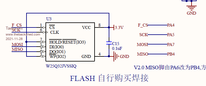 This is the V2 circuit. There is a reference to PA6 but nothing in English... I will have to do some tracing the hard way. Jim Edit: I did an on line translation: 'MISO pin is changed from PA6 to PB4, which is convenient for STM32F411 users to connect TF card and FLASH at the same time' Edited 2021-11-28 16:17 by TassyJim VK7JH MMedit |
||||
| Mixtel90 Guru Joined: 05/10/2019 Location: United KingdomPosts: 8683 |
Strange. Using a different MISO pin would certainly prevent a data clash on read if both were enabled together, but writes could probably corrupt either the SD or the flash or both. I could understand having different /CS pins - that makes sense to me. :) From Zephyr: I think most available boards are ver 3.0 now, so flash MISO is probably on PA6. That would appear to clobber using PA4 as SD_/CS if a flash chip is fitted. That doesn't matter because OPTION SDCARD sets the SD_/CS pin. Just don't use PA4 and it doesn't matter if a flash chip is fitted or not. Simples! . Edited 2021-11-28 18:09 by Mixtel90 Mick Zilog Inside! nascom.info for Nascom & Gemini Preliminary MMBasic docs & my PCB designs |
||||
| matherp Guru Joined: 11/12/2012 Location: United KingdomPosts: 11100 |
Good point: I'll set PA4 as an input with a pullup by default if not in use for SDcard. Assuming this is the case I will only be supporting MISO on PA6. Changing to PB4 would have multiple knock-on effects. Certainly my board which is a V3.0 clone uses PA6. Is there any merit to swapping the pins for SPI and SPI2 so that the onboard Flash could be used from MMBasic when the SDCard is enabled. I will be including some level of flash support in the firmware in a way that can co-exist with SDcard support so no change is necessary. This won't be a full file system but perhaps something like the PicoMite but extended to allow user read/write/erase as well Edited 2021-11-28 19:05 by matherp |
||||
| disco4now Guru Joined: 18/12/2014 Location: AustraliaPosts: 1109 |
Looks like only moved to PB4 on Version 2.0 boards. Moved back to PA6 at V2.1 and seems that it has not changed since. I don't have a board as yet so can't check it physically. From the Release Notes F4 H7FotSF4xGT |
||||
| matherp Guru Joined: 11/12/2012 Location: United KingdomPosts: 11100 |
411VGAV5.07.00a1.zip Drawing commands now working, colopurs are 0=black, non-zero=green(depending on which VGA pin you wire) CAPS/NUM lock leds now working for PS2 keyboard OPTION DEFAULT FONT fontnum [,scale]' sets the font used as the default. The fonts are the same 7 as the CMM2, default is OPTION DEFAULT FONT 1,1 Defaults PA4 to input with a pullup unless otherwise assigned Command recall at the prompt now implemented @ function implemented (e.g. print @(100,100)"Hello") Anyone up and running yet? 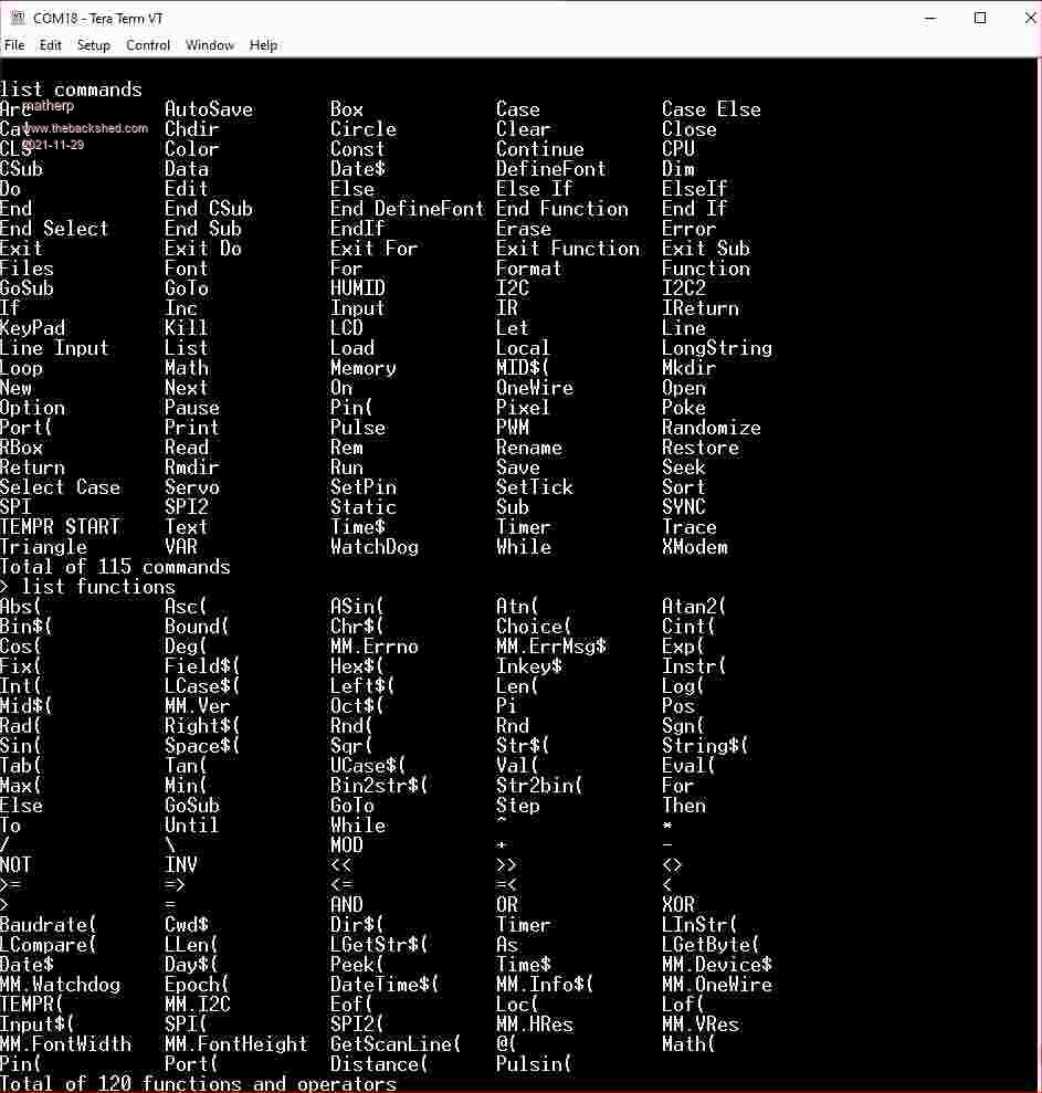 Edited 2021-11-29 00:12 by matherp |
||||
| Mixtel90 Guru Joined: 05/10/2019 Location: United KingdomPosts: 8683 |
Nope. I have a board but can't get it to connect to the PC at all. The blue LED is pulsing so the SOC is running. Tried to get into program mode while by holding BOOT0 while powering and by holding BOOT0 while pressing NRST. In both cases blue light goes out, just leaving PWR led lit. Windows doesn't see any sort of new device in device manager. I've just bought a new USB-C lead to try (I've tried two others). If that doesn't work I intend to try rigging up a USB-TTL converter onto the TX/RX data pins to try to bypass the USB connector but not got round to it yet. Too busy at the mo to mess with it - I'm modifying CMM2s. :) Update: The new USB-C lead is no better, even though this one comes in a packed labelled "Power & Sync" so I assume it has the data cores. :) . Edited 2021-11-29 02:19 by Mixtel90 Mick Zilog Inside! nascom.info for Nascom & Gemini Preliminary MMBasic docs & my PCB designs |
||||
| matherp Guru Joined: 11/12/2012 Location: United KingdomPosts: 11100 |
Just tested on my board Unplug. Hold down boot0 (nothing else). Plug in USB. keep boot0 held for a second or more. Release boot0 Run STM32CubeProgrammer. Select USB, you should see the serial number and then connect. I assume you have got STM32CubeProgrammer working with the CMM2? Via USB? If not then you may need drivers To do anything you must have a USB/UART connected to the console pins. Needed to enable the PS2 keyboard etc. Edited 2021-11-29 02:54 by matherp |
||||
| Page 1 of 5 |
|||||
| The Back Shed's forum code is written, and hosted, in Australia. | © JAQ Software 2026 |
