
|
|
Forum Index : Microcontroller and PC projects : PicoMite VGA Edition beta releases
| Page 1 of 5 |
|||||
| Author | Message | ||||
| matherp Guru Joined: 11/12/2012 Location: United KingdomPosts: 11493 |
Please find attached the first beta for the PicoMite VGA Edition. PicoMiteVGAV5.07.01b0.zip Special thanks to Miroslav Nemecek for the code used as the basis of the VGA driver. This runs exclusively on the second processor and has little of no impact on MMbasic performance. The only compromise is that the display has to be blanked when writing to flash as this can only happen with interrupts disabled. How fast the image returns depends on how fast your monitor re-establishes lock. This happens when exiting edit, exiting autosave, changing options, using VAR SAVE or using FLASH commands that write to flash. Otherwise the image seems very stable and clear. The PicoMite VGA Edition takes the existing Picomite code and makes the following changes: Program size reduced to 64Kbyte GUI and Touch functions removed PIO0 no longer available to MMBasic Support for all LCD displays removed OPTION CPU SPEED removed GP16, GP17, GP22 not available to MMBasic Support for a PS2 Keyboard added OPTION KEYBOARD NO_KEYBOARD/US/FR/GR/IT/BE/UK/ES Support for a 640x480 60Hz monochrome VGA display added and automatically configured OPTION CPU TURBO ON/OFF (126MHz or 252MHz) OPTION DEFAULT FONT fnt [, scale] 'e.g. OPTION DEFAULT FONT 7 All other PicoMite functionality should be as per the PicoMite manual Wiring: VGA GP16 connect to VGA socket pin 13 GP17 connect to VGA socket pin 14 GP22 connect to VGA Socket 1, 2, or 3 via 220ohm resistor Connect 1n4148 diode anode to VGA socket pin 1,2,or 3. Connect 1N4148 cathode (bar end) to GND Connect GND to VGA socket pins 5,6,7,8,10 PS2 Keyboard IMPORTANT use level conversion between the Pico pins and the PS2 socket or run the keyboard at 3.3V Connect GP8 to PS2 socket CLOCK pin via level converter (tested with this one) Connect GP9 to PS2 socket DATA pin via level converter Connect VBUS to PS2 socket +5V Connect GND to PS2 socket GND Enable the PS2 Keyboard with OPTION KEYBOARD IMPORTANT Clear the Pico flash with Clear_flash .zip before loading this firmware and if subsequently returning to the normal PicoMite firmware 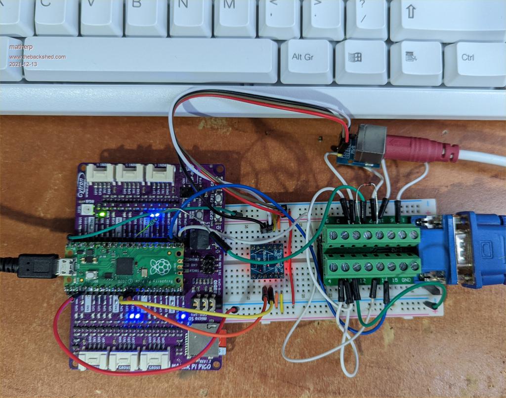 |
||||
| Mixtel90 Guru Joined: 05/10/2019 Location: United KingdomPosts: 8901 |
You deserve a bit of a rest now, Peter. You've just done two impossible things, VGA and PS/2 keyboard on the RPi PicoDog. :) Mick Zilog Inside! nascom.info for Nascom & Gemini Preliminary MMBasic docs & my PCB designs |
||||
| Poppy Guru Joined: 25/07/2019 Location: GermanyPosts: 486 |
 Yes! Great efforts (as usual!)! ... but where was the PS/2 issue, I think I missed it.  Andre ... such a GURU? Andre ... such a GURU? | ||||
| phil99 Guru Joined: 11/02/2018 Location: AustraliaPosts: 3289 |
An outstanding result. Really squeezing everything out of the Pico. The PS2 keyboard on my F4 needs 5V power but is happy with the pullups going to 3.3V. Only a sample of one but worth testing others. |
||||
| Mixtel90 Guru Joined: 05/10/2019 Location: United KingdomPosts: 8901 |
A lot of PS/2 keyboards seem to be happy at 3.3v on the clock & data lines. It's within 5v TTL spec. >2.7v is a high. Mick Zilog Inside! nascom.info for Nascom & Gemini Preliminary MMBasic docs & my PCB designs |
||||
| matherp Guru Joined: 11/12/2012 Location: United KingdomPosts: 11493 |
You are assuming a PS2 device never drives high, you may well be right but....... |
||||
| phil99 Guru Joined: 11/02/2018 Location: AustraliaPosts: 3289 |
Fair enough, tomorrow I will experiment with adding series resistors to see what can be tolerated. That should provide some safety, it works for serial coms. |
||||
| Mixtel90 Guru Joined: 05/10/2019 Location: United KingdomPosts: 8901 |
I read somewhere that the official spec for PS/2 keyboards is for open collector outputs. AFAIK that doesn't apply to mice, so there's no guarantee with those. I usually power mine at 3.3v anyway and they seem to work. :) Edited 2021-12-13 22:19 by Mixtel90 Mick Zilog Inside! nascom.info for Nascom & Gemini Preliminary MMBasic docs & my PCB designs |
||||
| Volhout Guru Joined: 05/03/2018 Location: NetherlandsPosts: 5924 |
Hi Peter, So this is then the end of the VGAmite ? Or will you be maintaining both ? Regards, Volhout PicomiteVGA PETSCII ROBOTS |
||||
| matherp Guru Joined: 11/12/2012 Location: United KingdomPosts: 11493 |
PicoMiteVGAV5.07.01b1.zip beta 1 Various tidy up changes but importantly I think I've solved the issue of dropping sync during flash writing. My nasty test program to exercise this Do Print "loop" i a=Rnd b=a VAR save a a=0 Pause 1000 VAR restore If a<>b Then Print "error" i=i+1 If i Mod 2 Then Option autorun on Else Option autorun off EndIf Loop Let me know if you get up and running with the PicoMite VGA Edition Edited 2021-12-14 03:39 by matherp |
||||
| flasherror Senior Member Joined: 07/01/2019 Location: United StatesPosts: 159 |
Regarding the color signal, does the Pico have the drive to connect all three R/G/B pins (for White) to GP22 via the 220 ohm resistor or should this just connect to ONE primary color pin on the VGA connector? Also, what are commonly used VGA (female DB15) and PS/2 keyboard connectors for PCB design? (not breakout boards) Edited 2021-12-14 09:51 by flasherror |
||||
| phil99 Guru Joined: 11/02/2018 Location: AustraliaPosts: 3289 |
Direct drive for one colour only. Each colour requires 8 or 9 mA, not much more can be supplied. Use an NPN emitter follower to get more drive. See VGAMite thread. For VGA and PS/2 layout see VGAMite PCB thread or Geoff's ASCII terminal project. Edited 2021-12-14 10:10 by phil99 |
||||
Grogster Admin Group Joined: 31/12/2012 Location: New ZealandPosts: 9975 |
Yes, I would also like to know if the VGAmite is now being abandoned for the PicoMite-VGA. Peter? Smoke makes things work. When the smoke gets out, it stops! |
||||
| Turbo46 Guru Joined: 24/12/2017 Location: AustraliaPosts: 1693 |
I hope not! I hope Peter is waiting for his boards to arrive. Bill Keep safe. Live long and prosper. |
||||
| phil99 Guru Joined: 11/02/2018 Location: AustraliaPosts: 3289 |
Tested 3 PS/2 keyboards. Hewlett Packard model SK-2501 requires 5V supply and 4k7 pullups to 3.3v - no internal pullups. Works normally with series resistors up to 3k9 - pullups at KB end. Microsoft model X08-76846 works well at 3.3V has weak internal pullups and extra pullups not needed. Works normally with series resistors up to 3k9 StarKey model KB-1616 works well at 3.3V has weak internal pullups and no extra pullups needed. Works normally with series resistors up to 1k0 but at 3k9 pullups needed at KB end and leds won't light up None of these drive high so series resistors not needed for them, but maybe not all stick to the standard. 1k0 series resistors would allow 1.7mA into a 3.3V pin from KB driving to 5V or about 0.5mA for 3k9. |
||||
| Mixtel90 Guru Joined: 05/10/2019 Location: United KingdomPosts: 8901 |
PS/2 is actually a bi-directional interface, which is why it's similar to I2C. The keyboard LEDs (not necessarily Shift Lock IIRC) are controlled from the computer end, not the keyboard. Consequently TTL *and* MOS logic levels apply. :) For PS/2 keyboards the best protection against 5v inputs is probably a 100R series resistor (keyboard protection insurance!) followed by a 2.7V zener, with the PicoMite pin taken from between them. The resistor shouldn't be too high as (if you are fussy about such things) the PicoMite *should* be able to sink the output pin to below 0.5v against the pullups. If you are going to rely on simple series resistors for protection against 5v inputs then you may have problems. Make it a potential divider and aim for about 2.7V at the input with 5V at the high end. Even a 2:1 divider will will work (giving 2.5V), but a High is only guaranteed above about 2.2V. As with all these things, what ultimately damages the chip is heat. Too much voltage pushes too much current through protection diode junctions and heats them up. They get damaged if the heat reaches that point, causing damage to the die in that area. However, brief excursions into the heating region cause no damage as the heat is conducted away by the substrate. A 50% duty cycle square wave, for example, might be fine, but anything over 70% might damage the chip. Mick Zilog Inside! nascom.info for Nascom & Gemini Preliminary MMBasic docs & my PCB designs |
||||
| matherp Guru Joined: 11/12/2012 Location: United KingdomPosts: 11493 |
Much better to do the level change properly 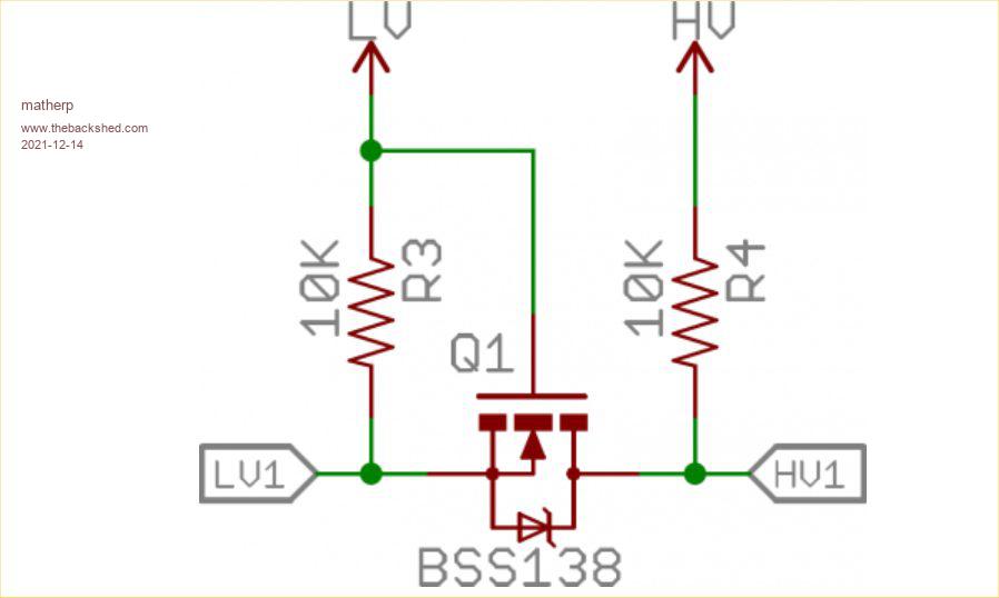 a cheap mosfet and two resistors. i.e. the incremental component count is two resistors and two mosfet |
||||
| atmega8 Guru Joined: 19/11/2013 Location: GermanyPosts: 738 |
Cheap and simple: https://www.amazon.de/dp/B095H64XSV/ref=sspa_dk_detail_3?psc=1&pd_rd_i=B095H64XSV&pd_rd_w=TVsAE&pf_rd_p=4f2ceb27-95e9-46ab-8808-db390b56ec01&pd_rd_wg=xG8a0&pf_rd_r=62A0MCG80D7JKGGZN0N9&pd_rd_r=21b1da41-bc76-45e7-b7e7-2651a71b7f82&spLa=ZW5jcnlwdGVkUXVhbGlmaWVyPUEzRFFBSVVJMzVQVkY0JmVuY3J5cHRlZElkPUEwMDA0MTIzMkhPVVM3VVM5NUhYNSZlbmNyeXB0ZWRBZElkPUEwODQ1NjYyMUZHTUo3RkFZV1o4TyZ3aWRnZXROYW1lPXNwX2RldGFpbCZhY3Rpb249Y2xpY2tSZWRpcmVjdCZkb05vdExvZ0NsaWNrPXRydWU= |
||||
| atmega8 Guru Joined: 19/11/2013 Location: GermanyPosts: 738 |
Hello Peter, thank you for this really cool and wonderfull VGA and PS2 Support. Some weeks ago it seemed to be unpossible. Now we have VGA. What about LCD Panels like ILI9488 and similar? Since VGA is not a problem of Memory, maybe this Displays will be to slow? Sorry if this "request" is too stupid. Glueckauf |
||||
| Mixtel90 Guru Joined: 05/10/2019 Location: United KingdomPosts: 8901 |
Both perfectly valid, but a proper level shifter is overkill for a PS/2 keyboard. :) All you really need are two zeners - the pullups will limit the current. Neither side is supposed to ever apply their supply voltage to either pin - from a hardware perspective it's I2C where the keyboard is the master. Any pullups built into the keyboard will tend to be between 1k and 10k so there's not a lot of zener current. Mick Zilog Inside! nascom.info for Nascom & Gemini Preliminary MMBasic docs & my PCB designs |
||||
| Page 1 of 5 |
|||||
| The Back Shed's forum code is written, and hosted, in Australia. | © JAQ Software 2026 |
