
|
|
Forum Index : Microcontroller and PC projects : PicoMite: PicoGAME VGA development
| Page 1 of 31 |
|||||
| Author | Message | ||||
| Mixtel90 Guru Joined: 05/10/2019 Location: United KingdomPosts: 8902 |
I have a preliminary design now and have run out of pins. :) Any comments on this spec before I take it further? PicoMite VGA (plugged in) - standard setup with PS/2 keyboard, level shifter, VGA, SD card etc. Audio socket has a header to select low/line or high/headphones Two Nunchuck ports (anyone know where to get the proper sockets? they would be nice.) Reset button MCP1700-3V3 Linear reg - onboard SMPS is disabled. 5V supply input via 3.5/1.3mm barrel jack USB-A socket for 5V out only. (can be used to power a VGA-HDMI converter) 9-pin Atari-compatible joystick port up-down-left-right-trigger-paddle A-paddle B - 3V3-GND 1-wire networking (but I'm not sure about a connector. 2.5mm jack?) Fits into the Hammond 1593WBK case if you happen to have one available. Costs too much to get a single one here, although they are available from Mouser, Digi-Key (6 UKP + 12 UKP postage!) & Farnell. PCB is 100mm x 98mm I realise that the 1-wire system may not be ideal for networking, but with a small number of players connected by twisted pair it should be fine if the message lengths are kept short, I think. There was only one pin left. I could have sacrificed the joystick port but I thought someone might fancy writing a simple flight simulator. ;) EDIT: Added position for additional 78xx-compatible switching regulator. This is to allow the board to be powered from up to 40V for use in caravans, on boats etc. The 5V supply from the USB-A socket is taken from this. Max total load is 800mA with short term up to 1A. It's purely optional and would normally be replaced with a wire link. Edited 2022-03-20 18:32 by Mixtel90 Mick Zilog Inside! nascom.info for Nascom & Gemini Preliminary MMBasic docs & my PCB designs |
||||
| thwill Guru Joined: 16/09/2019 Location: United KingdomPosts: 4369 |
Hey Mick, You seem to suffer the same obsession with designing PCBs that Peter does with porting MMBasic to new platforms  . .I love the relentless optimisim of the denziens of TBS as we try to recreate the 1980's microcomputer industry based on an ARM microcontroller and MMBasic - and I'm not immune, the heart says "yes", the brain says "don't be ridiculous". I'm not sure about the Atari joystick - it's digital (except for the 2 paddles, they need analogue pins) so not really suitable for a flight-simulator and it only has the one fire button. Also if you're going to have networking I think for a retro computer you really want to provide enough pins for serial, at least a TX and an RX - and I know you don't have enough pins, but I'm just saying  . .Anyway just to confirm that you are not alone in your madness, and with no obligation, and you'd probably be doing me a favour if you didn't, but if you design a version with 2 x DB9 connectors on the front to take NES controllers (found them cheap as chips on AliExpress): 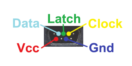 and another one on the back connected for minimal TX/RX serial then I will build at least one and (endeavour to) write a game that will run on the contraption - strictly speaking I will try to make a multiplayer version of @vegipete's "Rocks in Space" - unless he objects. But, please don't do this  , ,Tom MMBasic for Linux, Game*Mite, CMM2 Welcome Tape, Creaky old text adventures |
||||
| Mixtel90 Guru Joined: 05/10/2019 Location: United KingdomPosts: 8902 |
A basic flight sim could be done. You only need analogue ports (the paddle inputs) for the two joystick axes, everything else can be keyboard driven. I know it's not ideal, but it works - Microsoft flight sim used to work like that. I happen to have an analogue Flightstick which has a single DB9 connector, which was my main reason for putting one on. :) Hmmm... Not only have I never met a Nunchuck face to face, neither have I any experience with NES controllers. :) No idea how they work at all. Are you sure the modern equivalents aren't USB? EDIT: Just been discovering how NEC controllers work. Neat. :) Edited 2022-03-20 22:27 by Mixtel90 Mick Zilog Inside! nascom.info for Nascom & Gemini Preliminary MMBasic docs & my PCB designs |
||||
| thwill Guru Joined: 16/09/2019 Location: United KingdomPosts: 4369 |
Typo? Here is some MMBasic code to read one: Option Base 0 Option Default None Option Explicit 'Save "nes.bas" Const LATCH_PIN% = 9 ' GP6 Const CLOCK_PIN% = 10 ' GP7 Const DATA_PIN% = 11 ' GP 8 Const PULSE_DURATION! = 0.012 ' 12 micro-seconds SetPin LATCH_PIN%, Dout SetPin CLOCK_PIN%, Dout SetPin DATA_PIN%, Din Pin(LATCH_PIN%) = 0 Pin(CLOCK_PIN%) = 0 Dim i%, out% Do Pulse LATCH_PIN%, PULSE_DURATION! out% = &h0 For i% = 0 To 7 If Not Pin(DATA_PIN%) Then out% = out% Or 2^i% Pulse CLOCK_PIN%, PULSE_DURATION! Next If out% <> 0 Then If out% And &h01 Then Print "A "; If out% And &h02 Then Print "B "; If out% And &h04 Then Print "Select "; If out% And &h08 Then Print "Start "; If out% And &h10 Then Print "Up "; If out% And &h20 Then Print "Down "; If out% And &h40 Then Print "Left "; If out% And &h80 Then Print "Right "; Else Print ". "; EndIf Loop Best wishes, Tom MMBasic for Linux, Game*Mite, CMM2 Welcome Tape, Creaky old text adventures |
||||
| thwill Guru Joined: 16/09/2019 Location: United KingdomPosts: 4369 |
That explains why you were bothering to wire up the paddle pins. Does anyone know if this meant the Atari 2600 supported 4 paddles, never heard that it did ? Best wishes, Tom MMBasic for Linux, Game*Mite, CMM2 Welcome Tape, Creaky old text adventures |
||||
| Mixtel90 Guru Joined: 05/10/2019 Location: United KingdomPosts: 8902 |
Definite typo. LOL! I found a good video on youtube that shows what happens on a scope. The design for an *NES* version is coming along. Can't fit 2x DB9 along the back so might need to think of something else for a network socket (RJ11). I need the VGA, power and power out sockets on the back. Got 2x DB9 along the front ok though. :) Keyboard, SD card & audio on one side, PicoMite & Reset on the other. No power switch - pull the plug. :) I *could* make the board bigger to fit the CMM2 case but I have the same problem (P&P costs) getting those, they cost more and the PCB costs more. Anyway, I'm an awkward so and so. :) Mick Zilog Inside! nascom.info for Nascom & Gemini Preliminary MMBasic docs & my PCB designs |
||||
| thwill Guru Joined: 16/09/2019 Location: United KingdomPosts: 4369 |
Just spitballing, but if you are networking then you probably aren't using two controllers, could the P2 controller port be wired double duty to serve as the network/serial port? Likewise could the P1 controller port be wired double duty as an Atari port? Are you using the same PicoMite pin for latch and clock on the two controllers, I think you probably can, but might not be compatible with the double-duty ideas above. Best wishes, Tom Edited 2022-03-21 02:34 by thwill MMBasic for Linux, Game*Mite, CMM2 Welcome Tape, Creaky old text adventures |
||||
| Mixtel90 Guru Joined: 05/10/2019 Location: United KingdomPosts: 8902 |
This time I have the IO but not quite as much space. :) At the moment the two game ports are separate and COM1 has its own pins too. "Port 1" is currently on GP2, GP3, GP4 Yep... I could get COM1 to that easily enough. "Port 2" is currently on GP26, GP27, GP28. The latter isn't pin compatible with a "normal" joystick port, unfortunately, mainly because Trig is on 3V3! It might be possible to get enough connections to it to make it compatible with a Flightstick. I'll think about that one. Mick Zilog Inside! nascom.info for Nascom & Gemini Preliminary MMBasic docs & my PCB designs |
||||
| Turbo46 Guru Joined: 24/12/2017 Location: AustraliaPosts: 1693 |
@Mick, Have you considered a multiplexer for the ports? If you have the room. @Tom, Where do you find those controllers? I have difficulty sorting the wheat from the chaff. I can find none with the DB9 connector - all sorts of other options, USB and all manner of other connectors though. Bill Keep safe. Live long and prosper. |
||||
| thwill Guru Joined: 16/09/2019 Location: United KingdomPosts: 4369 |
Hi Bill, Can't be certain until I've had a chance to dissect one, but these appear to be "modern ones" at the right price with the right connector. https://m.aliexpress.com/item/32919127872.html I've got 4 coming on the slow boat from China. Best wishes, Tom MMBasic for Linux, Game*Mite, CMM2 Welcome Tape, Creaky old text adventures |
||||
| Mixtel90 Guru Joined: 05/10/2019 Location: United KingdomPosts: 8902 |
Prelim PCB later this evening. Have it sorted, I think. Port 1 is NES + PADDLE-A / COM1 Port 2 is NES / ATARI with both paddles. Select ATARI mode in software. Port 1 would need an adapter for a normal paddle as + is on the wrong pin and there is no Trig - one of the other pins would have to be used. Mick Zilog Inside! nascom.info for Nascom & Gemini Preliminary MMBasic docs & my PCB designs |
||||
| Turbo46 Guru Joined: 24/12/2017 Location: AustraliaPosts: 1693 |
Thanks Tom, I may have to get a couple to play with, maybe a third so I can chop the cable to bits. If I remember correctly your original one only had 2 buttons? Yes, A and B, I just looked again at your code which does look familiar, I remember the: out% Or 2^i% Bill Edit: They may be different inside, two extra buttons means 10 bits unless they do something tricky. I can't find a circuit for the 4 button one. . Edited 2022-03-21 06:27 by Turbo46 Keep safe. Live long and prosper. |
||||
| thwill Guru Joined: 16/09/2019 Location: United KingdomPosts: 4369 |
Original NES controllers have a 4 directional D-pad and A, B, Select and Start buttons. Internally they contain just a 4021 shift register and a bunch of pull up resistors. Some clones and 3rd parties added an oscillator and two additional "autofire" buttons that just simulate the A and B buttons being pressed repeatedly. I am assuming that is what is on these controllers, but I may be in for a surprise. Note 1: the real NES (at least the ones we saw in Europe) did not have a DB9/Atari connector but one of these https://encrypted-tbn0.gstatic.com/images?q=tbn:ANd9GcT-w7Z0JuuOpGDb2mQ57ERGiww2zxqcEDM0Ng&usqp=CAU. The DB9 connectors appeared on the clone machines. Note 2: in Japan the NES is called a Famicom and is cosmetically very different. It may have had the DB9 port or something completely different, I haven't researched it properly. Best wishes, Tom MMBasic for Linux, Game*Mite, CMM2 Welcome Tape, Creaky old text adventures |
||||
| Mixtel90 Guru Joined: 05/10/2019 Location: United KingdomPosts: 8902 |
Preliminary design: 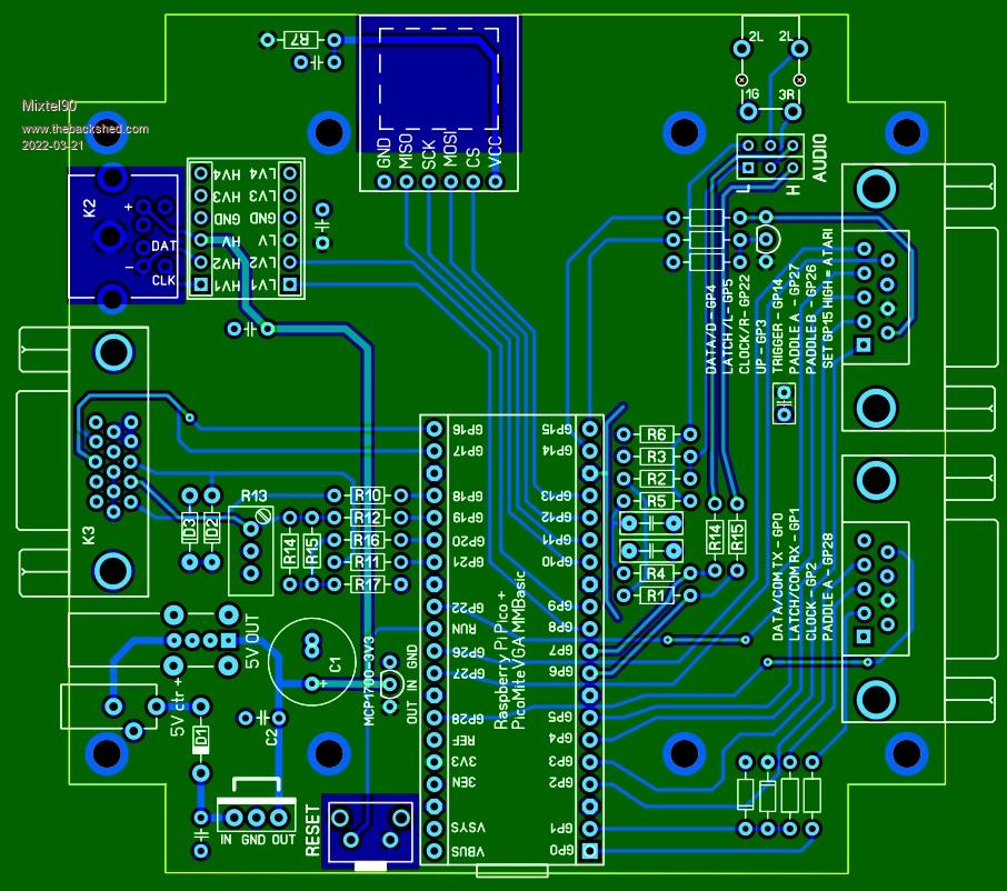 Yes, Tom, I rather enjoy designing PCBs. :) I used to be an electrical design draughtsman in earlier times so it's nice to do CAD type stuff where I can see the finished results. Edited 2022-03-21 06:39 by Mixtel90 Mick Zilog Inside! nascom.info for Nascom & Gemini Preliminary MMBasic docs & my PCB designs |
||||
| Turbo46 Guru Joined: 24/12/2017 Location: AustraliaPosts: 1693 |
Yes, I forgot about that, hopefully that's it. Thanks Bill Edit: Ah, found the circuit 'Turbo A' and 'Turbo B', that's what the TA and TB mean. I like the names. . Edited 2022-03-21 06:53 by Turbo46 Keep safe. Live long and prosper. |
||||
| thwill Guru Joined: 16/09/2019 Location: United KingdomPosts: 4369 |
I guess my bluff has been well and truly called and I will be writing/adapting a game for Multiplayer on the VGA PicoMite. It's a good job those controllers aren't here until June, that will give me a bit of time to try and get some other things finished first. Best wishes, Tom Edited 2022-03-21 06:55 by thwill MMBasic for Linux, Game*Mite, CMM2 Welcome Tape, Creaky old text adventures |
||||
| Turbo46 Guru Joined: 24/12/2017 Location: AustraliaPosts: 1693 |
You could replace that cable on your existing controller.  Bill Keep safe. Live long and prosper. |
||||
| thwill Guru Joined: 16/09/2019 Location: United KingdomPosts: 4369 |
That suggestion is just your revenge for persuading you to do a dozen revisions of The Great Blackberry Adventure. Tom MMBasic for Linux, Game*Mite, CMM2 Welcome Tape, Creaky old text adventures |
||||
| Mixtel90 Guru Joined: 05/10/2019 Location: United KingdomPosts: 8902 |
Hehe... That'll teach you to give me a challenge. ;) Circuit diagram tomorrow night, probably, then you can see how I work my magic. lol Not sure if I should put some sort of protection on the joystick inputs - or external pull-down resistors anyway. Might be a good idea. Mick Zilog Inside! nascom.info for Nascom & Gemini Preliminary MMBasic docs & my PCB designs |
||||
| Turbo46 Guru Joined: 24/12/2017 Location: AustraliaPosts: 1693 |
@Tom, A dozen? That was only in the last email. @Mick, I don't know about the Pico but I've had trouble using the Micromite's weak internal pullup resistors for switch inputs even on a short length of wire. I was getting false triggering from noise. Do you mean PULLUP resistors? Bill Keep safe. Live long and prosper. |
||||
| Page 1 of 31 |
|||||
| The Back Shed's forum code is written, and hosted, in Australia. | © JAQ Software 2026 |
