
|
|
Forum Index : Microcontroller and PC projects : dim var as byte
| Author | Message | ||||
| Mixtel90 Guru Joined: 05/10/2019 Location: United KingdomPosts: 7815 |
There are *loads* of PCB designs for the PicoMite and PicoMite VGA. :) �Just not on ebay. If you want a "backpack" board for the ILI9341 I did one of those a while ago. Have a look at the link in my sig, it's listed there - both gerbers and the manual. I *think* I may still have some boards left. Check out the manual and see if it's what you want. EDIT: To solder the pins onto a Pico there's a very easy way. Use an old breadboard (you might ruin the contacts on a new one - a cheap one will do). Put the pins into it, with the Picoon them and push them part way in. Check down the sides to make sure that the Pico isn't bowed. Solder end and a middle pin on each side then check again. Finish soldering the lot, unplug and go. Everything is lined up perfectly and there's no stress on the pins. Edited 2022-08-20 07:18 by Mixtel90 Mick Zilog Inside! nascom.info for Nascom & Gemini Preliminary MMBasic docs & my PCB designs |
||||
| stanleyella Guru Joined: 25/06/2022 Location: United KingdomPosts: 2518 |
page 48 in the manual- "If you run into trouble getting the display to work it is worth disconnecting everything and clear the options with the command OPTION CLEAR so that you can start with a clean slate. Then reconnect it one stage at a time and configure and test each new stage as you progress. First the SD card interface, then the LCD display and finally the touch interface" if you start with the suggested sd card ie option sdcard gp22 it says error : System SPI not configured... which makes sense cos it's not connected. syrro this is hard to understand...I'm Welsh Edited 2022-08-20 07:57 by stanleyella |
||||
| stanleyella Guru Joined: 25/06/2022 Location: United KingdomPosts: 2518 |
These commands will be remembered and automatically applied on power up. Note that after each command is entered the PicoMite will restart, and the USB connection will be lost and must be reconnected. Next the touch screen should be calibrated: GUI CALIBRATE You can then test the various components. The following will list the files on the SD card, if it executes without error you can be assured that the SD card interface is good. FILES The following will draw multiple colourful overlapping circles on the LCD screen which will confirm that the LCD is connected correctly: GUI TEST LCDPANEL Finally, the following will test the touch interface. When you touch the LCD screen a dot should appear on the screen at the exact point of the touch. GUI TEST TOUCH If this is not accurate you may have to run the GUI CALIBRATE command a second time taking greater care. If you run into trouble getting the display to work it is worth disconnecting everything and clear the options with the command OPTION CLEAR so that you can start with a clean slate. Then reconnect it one stage at a time and configure and test each new stage as you progress. First the SD card interface, then the LCD display and finally the touch interface. Also note that the ILI9341 controller is sensitive to static discharge so, if the panel will not respond, it could be damaged and it would be worth testing with another panel. |
||||
| stanleyella Guru Joined: 25/06/2022 Location: United KingdomPosts: 2518 |
Mix, you said you preferred the vga mmbasic in a post. I think you've forgotten lcd stuff. I think vga not as valid as lcd support. If you look at other forums you'd see the trouble people go to to get a touch screen working. mmbasic for lcd sorts all that. I got a rpi400 and retropi ie emulation station and rpi runs off usb3 ssd and retropi runs off usb3 ssd. many systems and games. 3500 zxspectrum games so it takes minutes to load and there's some I wrote. I got games like n64 starwing or pilot wings I used to play with my kids and the nostalgia overload is too much. They've seen them and remember them. I don't think I'll use mmbasic vga... there's vga games on the forum and they look a lot to learn compared to glcd. |
||||
| Mixtel90 Guru Joined: 05/10/2019 Location: United KingdomPosts: 7815 |
GCB is a compiler all of its own. How they chose to do ADC setup is completely up to them. :) �I do know it works though. It's lower level than the PicoMite as it doesn't do any de-noising or scaling IIRC - it just gives you a number which is the analogue value at that instant. If you want to remove noise then you have to do something like MMBasic does automatically. Is it the same sort of display that you've been using? Now you're using the "upside down" board you'll have to be extra careful with your wiring, won't you? I think I'd be tempted to use it right way up and connect to it using female Dupont leads rather than plug it into a breadboard. I don't know - I've never tried to use one like that. Don't connect the SD card until you have the display and Touch working. Connect Touch_EN (I'm not sure what the pin name is off-hand) high initially to disable touch until you have the display working. What's your OPTIONs list? I've certainly not forgotten about LCD display. :) As I said, you lose Touch so it's essential for a lot of stuff. I just happen to prefer programming on the VGA version as I use the built-in editor. I very rarely use the console unless I'm debugging. I can't even see it as I only have a single monitor and it's a faff switching it between console and display. I know I could just use a LCD as the display, but it's something else to clutter my little table up with and I've no spare ones anyway. Edited 2022-08-20 17:13 by Mixtel90 Mick Zilog Inside! nascom.info for Nascom & Gemini Preliminary MMBasic docs & my PCB designs |
||||
| lizby Guru Joined: 17/05/2016 Location: United StatesPosts: 3347 |
The manual appears to be in error, since no "OPTION CLEAR" is supported (and it's not listed in the OPTIONs section). OPTION LCDPANEL DISABLE is what you want to be able to reset LCD options. There's also an "OPTION RESET"--but there are two entries for it in the manual; one has the description "Clears all options"; the other says "Reset all saved options to their default values" (I don't know exactly what that means with respect to OPTION LCDPANEL). I suspect the second OPTION RESET should be removed from the manual. PicoMite, Armmite F4, SensorKits, MMBasic Hardware, Games, etc. on fruitoftheshed |
||||
| stanleyella Guru Joined: 25/06/2022 Location: United KingdomPosts: 2518 |
If my posts are irritating then I apologise. Everyone was a new user once. Why would I intentionally want to upset people who have made the effort to help me?? An observation- never seen a-d values adjusted or played with using picaxe or gcb, people just use the value. No one seems to mention noise. This is all I expect from just reading a-d pin. Noise does not seem to show. This is a really cheap 100k potentiometer connected between ground and 5V and I am just displaying the voltage. The potentiometer was an old carbon one and audio would be noisy but my display seems stable. https://www.youtube.com/watch?v=d51PTF8Boh0 Edited 2022-08-21 00:52 by stanleyella |
||||
| Mixtel90 Guru Joined: 05/10/2019 Location: United KingdomPosts: 7815 |
Assuming you are using GP26 as an input, all you need to do in MMBasic is: SETPIN GP26, AIN myvoltage = PIN(GP26) myvoltage is set to a value between zero and 3.3 by default. I'm pretty sure it can't get much easier. The SETPIN command is necessary as GP26 can also be used for other purposes, so we have to set it up for the ADC. You only do it once in your program. If you want to stop using it as an ADC input then use SETPIN GP26, OFF which will free it off to be used for something else. You don't know if the Picaxe or GCB PIC chips have noisy inputs or not. They might be filtering the noise just as MMBasic does as the process is completely transparent to you. All ADC inputs are noisy simply because there are all sorts of noises around, including on the supply rails and RF broadcasts. One of the arts of working with ADCs is in learning how to minimise that noise. Edited 2022-08-21 01:42 by Mixtel90 Mick Zilog Inside! nascom.info for Nascom & Gemini Preliminary MMBasic docs & my PCB designs |
||||
| stanleyella Guru Joined: 25/06/2022 Location: United KingdomPosts: 2518 |
Thanks for the advice. I just setup rpipico third one and soldered headers so button is up and can not see the useless labels. Loaded mmbasic, connected ili9341 and powered it from vbus which measured 5V but flashing horizontal lines partially across the lcd. Hmmm... Using 3.3Vout sorted it. I used the example ili9341 setup in the manual and it all works, display circles, touch calibrate and touch test and read files on sd card all working. Maybe soldering the headers other way could have damaged second pico but it worked in teraterm. anyway I'm pleased pico 3 is working as a spare. |
||||
| lizby Guru Joined: 17/05/2016 Location: United StatesPosts: 3347 |
If you haven't seen it with PICAXE, you haven't read all the pertinent posts. When using an ADC on the PICAXE, I've regularly used a method someone posted sometime--read 10 values, throw away the high and low, and average the remainder. Even absent significant noise (or if you worked to minimize it), there will always be points in the range you are looking at at which you will experience dither--fluctuation between readings in the least significant bit (at least). It's a fundamental aspect of converting an analog signal to digital. PicoMite, Armmite F4, SensorKits, MMBasic Hardware, Games, etc. on fruitoftheshed |
||||
| stanleyella Guru Joined: 25/06/2022 Location: United KingdomPosts: 2518 |
I notice pico 1 is com13, pico 2 is com 14, pico 3 is com 15 and it is remembered on win 10. I had to reset mmedit for new com but easy and works. The ili9341 in the manual works. The wiring and the options. I am glad I set up the lcd for portrait. now to start coding a-d. using manual and posted code examples. |
||||
| Mixtel90 Guru Joined: 05/10/2019 Location: United KingdomPosts: 7815 |
Windows recognises individual devices and will create a new COM port for any that it doesn't already recognise. It will almost always connect a device to the COM port it was originally given. Mick Zilog Inside! nascom.info for Nascom & Gemini Preliminary MMBasic docs & my PCB designs |
||||
| stanleyella Guru Joined: 25/06/2022 Location: United KingdomPosts: 2518 |
arduino on win 10 and same device different com port each time I use it. tried on other pc and laptop same. Anyway I'm happy I got 2 mmbasic working boards. I got 8 channel bi-direction logic level converters but mistakes and 5V into pico gp pin and broken so plan b, a backup :) 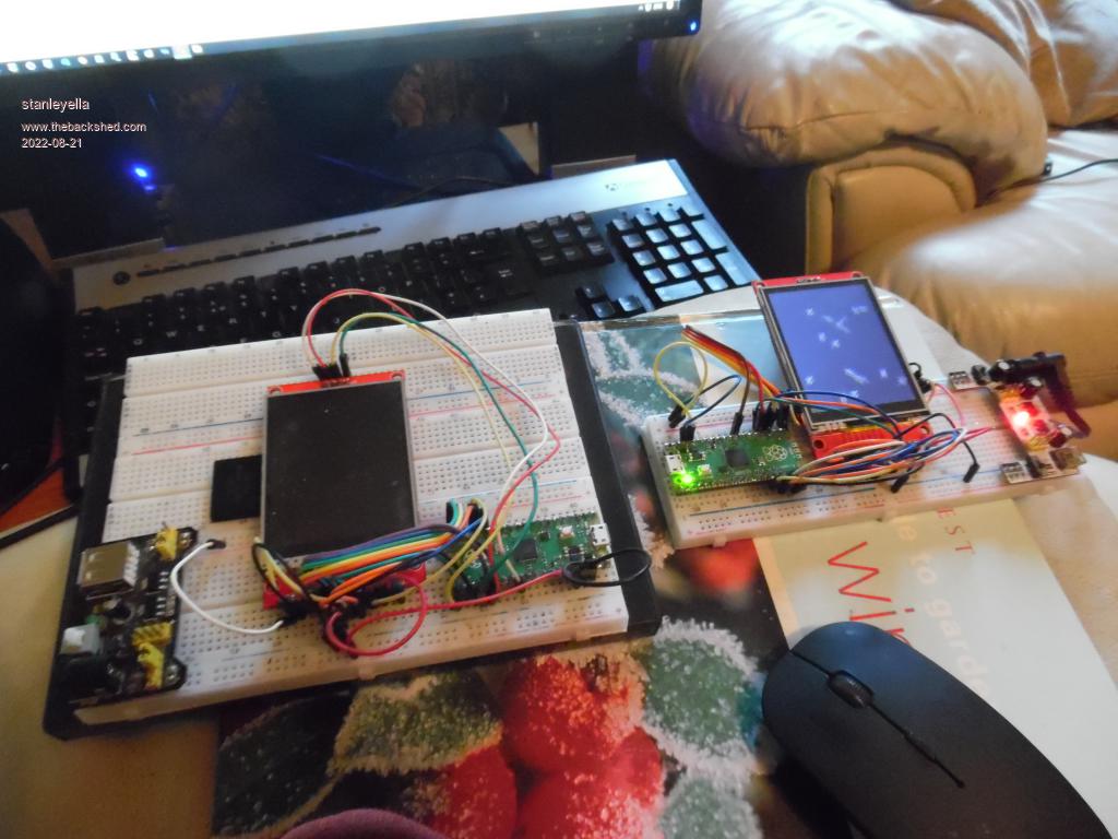 |
||||
| stanleyella Guru Joined: 25/06/2022 Location: United KingdomPosts: 2518 |
This gives 1 and 2 maybe when the pin is touched . not sure of convert vars to strings if that is only way of printing vars on lcd SETPIN GP26, AIN cls do myvoltage = PIN(GP26) text 0,0,Str$(myvoltage) loop |
||||
| Mixtel90 Guru Joined: 05/10/2019 Location: United KingdomPosts: 7815 |
That's right. TEXT can only output strings. The ADC pin inputs are very high impedance. It's better to put a resistor to ground to keep them stable with little or no input, otherwise they will float to about half supply voltage. You are seeing an average of the maximum that the input can handle, so about 1.6V. Read up on the STR$() function to change the way it formats the string. Mick Zilog Inside! nascom.info for Nascom & Gemini Preliminary MMBasic docs & my PCB designs |
||||
| panky Guru Joined: 02/10/2012 Location: AustraliaPosts: 1114 |
With the greatest respect to stanleyelle, this post seems to have degenerated into miscellaneous ramblings about getting a Picomite up and running as well as all sorts of hardware and software questions with nothing to do with the original post. It might be better to close this thread and start a new thread for each topic/problem - that way, Backshed members can more easily assist with each specific issue. This also helps others find answers/solutions to problems - ie. the problem and solution are neatly linked together in the one post. Just my 2 penneth worth and not intended to discourage anyone from posting issues. panky ... almost all of the Maximites, the MicromMites, the MM Extremes, the ArmMites, the PicoMite and loving it! |
||||
| Mixtel90 Guru Joined: 05/10/2019 Location: United KingdomPosts: 7815 |
Much as I agree with you, panky, from my previous experience as a mod on another forum it's sometimes an idea to simply accept thread drift and keep all the stuff in one place rather than have umpteen threads. Stanleyella is a newbie to MMBasic and tends to have a lot of questions so that's a lot of threads. :) It's not likely that any of his questions so far will be things that others will be searching for. He has a point though, stanleyella, now you're finding your feet a bit it might be a good idea to take his advice and try to keep to (more or less) one subject per thread. :) Mick Zilog Inside! nascom.info for Nascom & Gemini Preliminary MMBasic docs & my PCB designs |
||||
| stanleyella Guru Joined: 25/06/2022 Location: United KingdomPosts: 2518 |
Point taken. It was originally about mmbasic variables and transferring programs to mmbasic. I have received a lot of good advice. Thank you. |
||||
| The Back Shed's forum code is written, and hosted, in Australia. | © JAQ Software 2025 |
