
|
|
Forum Index : Microcontroller and PC projects : dim var as byte
| Author | Message | ||||
| Mixtel90 Guru Joined: 05/10/2019 Location: United KingdomPosts: 7889 |
You can't reduce noise from the SMPS much. It's all over the board. A capacitor from VREF to GND will probably help a little, but not much. Disabling the SMPS and changing to a linear reg makes a big difference, I enjoy designing PCBs now. lol Keep them reasonably small and they are cheap too. Mick Zilog Inside! nascom.info for Nascom & Gemini Preliminary MMBasic docs & my PCB designs |
||||
| stanleyella Guru Joined: 25/06/2022 Location: United KingdomPosts: 2548 |
is there a function to scale 0 to 255 if that's an 8bit a-d read to 0 to 3.3? manual looked stan not ... yoda did |
||||
| phil99 Guru Joined: 11/02/2018 Location: AustraliaPosts: 2626 |
The A-D read is more than 8 bits but because of an error on the chip its accuracy is sometimes only 8 bits. Its just a matter of not using it for programs that require greater accuracy. The ideal solution is to use an external A-D chip. For some situations it might be enough to use an op-amp to pre-scale the input voltage to minimize the effect of the error. Eg. If using a thermistor to measure air-con. temperature the op-amp circuit could convert a temp range of 15 C - 25 C to a 0.0V - 3.3V range for the Pico. With 8 bit accuracy covering just 10 degrees there is no real problem. |
||||
| stanleyella Guru Joined: 25/06/2022 Location: United KingdomPosts: 2548 |
ps the manual.... ground 3.3 en and use a 3.3 linear reg an improvement? the idea was it was a cheap system, no extra stuff needed for reading a-d... rpipico fault. An ili9341 is 3.3v logic but 5v supply through a 3.3v on board reg and jp1 which shorts it out so it runs off 3.3v. dunno about the led backlight which seems ok with 3.3 or 5v. so as my breadboard supply has two switchable 3.3/5v supplies then guess run the pico off 3.3v rail and the lcd from 5v rail? Wonder how fast it samples. Well ground 3.3 enable and power the 3.3vout from 3.3v works. use usb to load code with it wired and supplied and it loads and removing usb lead it still works. maybe it will be cleaner. I ran the lcd and led backlight from 5v rail 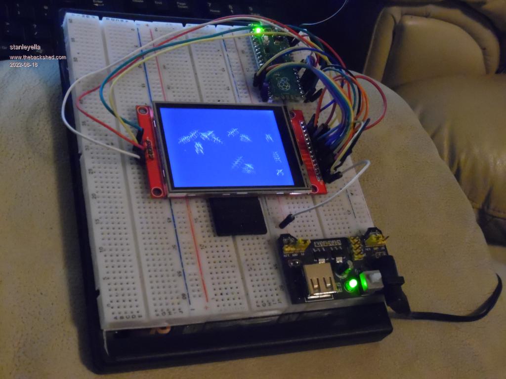 . the wall plug is 6.5v sm 600ma |
||||
| Mixtel90 Guru Joined: 05/10/2019 Location: United KingdomPosts: 7889 |
If that's the normal ILI9341 (it looks like it is) you can run it from 5V. The 5V supply is, I think, used as the main supply to the backlight, which (on current versions) is driven by a transistor from the controller chip. The backlight draws quite a bit of current at high brightness levels so it makes more sense to feed that at 5V. The controller chip itself is fed via an on-board 3V3 regulator so all I/O pins are at 3V3, even with a 5V supply. You can feed the PicoMite at 3V3 (via the 3V3 pin) but you must connect 3V3EN to GND to disable the SMPS. MMBasic takes a string of A_D samples, discards the first and last then averages the remainder to get a final value. This is all done automatically. It also automatically scales the A-D input so that you read the actual voltage on the pin. Mick Zilog Inside! nascom.info for Nascom & Gemini Preliminary MMBasic docs & my PCB designs |
||||
| stanleyella Guru Joined: 25/06/2022 Location: United KingdomPosts: 2548 |
The last image shows the ili9341 running off 5V and the led at 5V. The picomite is 3.3EN grounded and 3.3V is fed into 3.3V out. Works with no usb. The A-D seems a slow implementation but yet to try. External a-d? I got a lgt328p that runs at 32MHz and has "12-channel 12-bit high-speed analog-to-digital converter (ADC)". It could be used as a-d but communicating info to picomite would be serial? so slow. Pity, I was expecting more from picomite a-d. |
||||
| JohnS Guru Joined: 18/11/2011 Location: United KingdomPosts: 4038 |
It's due to the buggy Pico hardware. (Still incredibly good value.) John |
||||
| Mixtel90 Guru Joined: 05/10/2019 Location: United KingdomPosts: 7889 |
There are much nicer A_D chips available with I2C connection. As it happens, I2C on the PicoMite isn't difficult. You also gain the possibility of having a quieter power supply for the converter. If you want quantity of ADC inputs you could use a 28-pin Micromite to give you 10 analogue inputs over I2C. Program it to run a "round robin" to keep 10 registers updated and averaged out. It should be pretty good. Mick Zilog Inside! nascom.info for Nascom & Gemini Preliminary MMBasic docs & my PCB designs |
||||
| stanleyella Guru Joined: 25/06/2022 Location: United KingdomPosts: 2548 |
from the manual if I only use 1 a-d channel then it's the fastest way. lots of stuff about arrays to set up for storing samples. I'm more used to dir portc.0 in : adval=ReadAD(an0) for a scope maybe, 1 channel real time. https://www.youtube.com/watch?v=Y3QTnrOUeHQ&t=12s |
||||
| JohnS Guru Joined: 18/11/2011 Location: United KingdomPosts: 4038 |
Which would mean you have to do the (quite slow) noise-removal coding that MMBasic does for you. Swings & roundabouts... John |
||||
| Mixtel90 Guru Joined: 05/10/2019 Location: United KingdomPosts: 7889 |
You can use the ADC in two different ways. The easy way is to simply use SETPIN to set up a pin as analogue then x=PIN(n) sets x to the voltage on PIN(n). This takes multiple samples and gives you the average. The other way is to use ADC OPEN to set up the ADC pins to automatically run one after the other at a set frequency. Using this method the values are stored in arrays so you can use your own averaging system or none, depending on how big you make your arrays. You are tied to reading them in the order GP26, GP27, GP28, GP29 though and the first has to be GP26. Mick Zilog Inside! nascom.info for Nascom & Gemini Preliminary MMBasic docs & my PCB designs |
||||
| phil99 Guru Joined: 11/02/2018 Location: AustraliaPosts: 2626 |
The ADC method could make it possible to reduce the effect of the hardware fault. First add a low pass filter to the pin(s) you are using. Its corner frequency should be as low as your application can accept. Before doing your noise reduction check (delta V) / (delta t) for each pair of samples and discard (or replace with interpolated value) any samples that exceed the maximum (delta V) / (delta t) of the filter. Any samples that exceed the slew rate of the filter must be due to internal glitches. |
||||
| Mixtel90 Guru Joined: 05/10/2019 Location: United KingdomPosts: 7889 |
That's an interesting idea... Mick Zilog Inside! nascom.info for Nascom & Gemini Preliminary MMBasic docs & my PCB designs |
||||
| stanleyella Guru Joined: 25/06/2022 Location: United KingdomPosts: 2548 |
I've grounded 3.3EN and run 3.3out from a 3.3V linear reg. Dunno about adref pin. Scoped the 3.3v in and not noisy. Using 8bit mega328 adval=ReadAD(an0) I don't know what it does as it's in the compiler. I'll ask on another forum to see. Until now a-d was just a function I took for granted. |
||||
| stanleyella Guru Joined: 25/06/2022 Location: United KingdomPosts: 2548 |
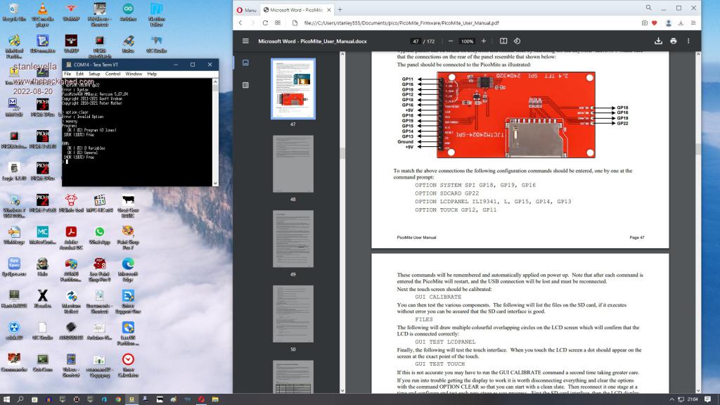
I asked what happens when you read an a-d pin and answer was "GCB setups the ADC, reads it. Provides the result back to user. If you need more samples and noise handling then users would add this in the user code." My reply was Thanks. That's always worked for me. so none the wiser ie GCB setups the ADC I may find a-d works ok for me but got side tracked getting second rpipico working with lcd. I put the headers in the other way so I could see the "labels" but they're useless and makes it easy to make mistakes as the left right pins reversed. Also someone mentioned broken molex leads, got to check them not take for granted when got problems. teraterm it works but any lcd it's invalid option or syntax. Other board works fine. Swapped displays etc. Got one more rpipico to solder headers to. |
||||
| lizby Guru Joined: 17/05/2016 Location: United StatesPosts: 3367 |
If you're getting that, it's not the fault of teraterm. Try posting the code and the response. PicoMite, Armmite F4, SensorKits, MMBasic Hardware, Games, etc. on fruitoftheshed |
||||
| stanleyella Guru Joined: 25/06/2022 Location: United KingdomPosts: 2548 |
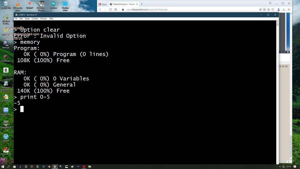
 mmbasic on rpipico is working? no connections to lcd but clear showed errorr as all lcd commands when wired. lcd is working. Edited 2022-08-20 06:06 by stanleyella |
||||
| stanleyella Guru Joined: 25/06/2022 Location: United KingdomPosts: 2548 |
 |
||||
| stanleyella Guru Joined: 25/06/2022 Location: United KingdomPosts: 2548 |
Buy rpipico with soldered headers. life's too short. if there's an ili board for your display get one if it's just sockets and no fun of soldering :( nothing much on ebay |
||||
| matherp Guru Joined: 11/12/2012 Location: United KingdomPosts: 10273 |
If you want help why not try taking the time to write in English using normal syntax and punctuation. Lots of forum members who don't have English as a first language seem to manage it perfectly well. Please explain where in the manual you have found the command "OPTION CLEAR" since no-one else can find it? |
||||
| The Back Shed's forum code is written, and hosted, in Australia. | © JAQ Software 2025 |
