
|
|
Forum Index : Microcontroller and PC projects : PicoMite: driving a passive buzzer
| Page 1 of 4 |
|||||
| Author | Message | ||||
| thwill Guru Joined: 16/09/2019 Location: United KingdomPosts: 4369 |
Hi folks, I have some passive buzzers "Mini Piezo Passive Buzzer (9042) 16 ohm, 3V" and I'd like to get some life out of them on a PicoMite (non-VGA if that matters). The monkey's first effort: 1. OPTION AUDIO GP0, GP1 2. Connect (+) on buzzer to GP0, Connect other buzzer to GND 3. PLAY TONE 600, 600, 1000 4. Very, very faint buzz PLAY SOUND 1,L,S,600,25 or PLAY SOUND 1,B,S,600,25 seems to produce nothing. I guess this is something to do with "The audio signal is superimposed on a square wave as a pulse width modulated (PWM) signal ..." but the solution given in the manual to that "... a low pass filter is required ..." which I can build/copy then needs a "following amplifier" (whatever that might happen to be) after it. Can I make PLAY TONE/SOUND work with a buzzer and some basic components ? This is for a little hand-held game project. I have also driven one of these buzzers connected to GP2 with PWM directly: 1. SETPIN GP2,PWM1A 2. PWM 1,600,50 3. An audible tone So this is better if rather "closer to the machine" than I was hoping to go. Note that the manual (at least the version I have) says the duty for the PWM command is optional, though not the comma before it ... this does not seem to be true, you get a syntax error if no duty is supplied. PWM channel, frequency, [dutyA] [,dutyB] I also had some problems with the syntax and the PicoMite rebooting with "Error : Invalid address - resetting" but I think that has been resolved by a firmware update. Best wishes, Tom MMBasic for Linux, Game*Mite, CMM2 Welcome Tape, Creaky old text adventures |
||||
| phil99 Guru Joined: 11/02/2018 Location: AustraliaPosts: 3295 |
One I have used (from an old microwave oven) was very fussy about the frequency. Quite loud at resonance. Sweep the PWM from 400Hz to 2kHz or so to find the loudest point. |
||||
| thwill Guru Joined: 16/09/2019 Location: United KingdomPosts: 4369 |
Thanks Phil, but I don't think that is the problem I am trying to solve, I CAN get a buzz out of it using the PWM command but I'd like to get music out of it using PLAY SOUND. However from the manual my understanding is that PLAY SOUND (and PLAY TONE) expect a "low pass filter" and some sort of amp to be connected to the pins, and tying the buzzer to the appropriate PWM pin isn't going to cut it. I'm hoping the cognizante will be able to tell me what I need to build ... or conversely tell me I am on a fool's errand. ... it may also be that I am going to have to rewrite my MMBasic music engine to use PWM directly, in which case I assume I am still going to want some sort of "protection" between the PicoMite PWM pin and the buzzer. Best wishes, Tom Edited 2022-11-28 22:41 by thwill MMBasic for Linux, Game*Mite, CMM2 Welcome Tape, Creaky old text adventures |
||||
| Martin H. Guru Joined: 04/06/2022 Location: GermanyPosts: 1460 |
in German but I think you ll get it: RC Low Pass 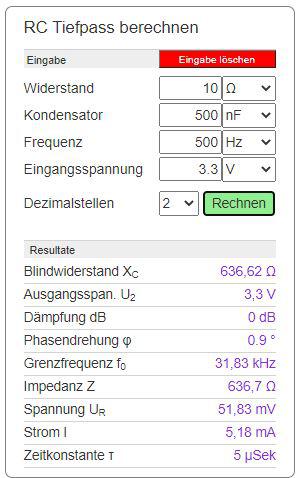 cheers Mart!n Edited 2022-11-28 23:05 by Martin H. 'no comment |
||||
| Mixtel90 Guru Joined: 05/10/2019 Location: United KingdomPosts: 8913 |
You should have a resistor/capacitor filter off the pin to get rid of the carrier frequency of the PWM. However, you might get away without them - or with just a capacitor - if driving one of the little passive sounders. The problem is that the sounders have a truly horrible frequency response and are designed to resonate over a narrow range to get maximum beep volume. You'd be far better getting one of the small laptop speakers which, although they are still horrible, at least attempt more than one frequency. You may need more volume than you can get from the 3V3 supply. I'd be tempted to try a simple 1-transistor output stage on the 5V rail: 5V | speaker |c |/ --- 1k --| |---| NPN 1u |\ V |e ---+--- GND You should have Geoff's R/C network in front of this. You may also need a small resistor in series with the speaker if the transistor gets hot (it shouldn't). Note that this is *very* crude and can be improved a lot by adding bias resistors. Mick Zilog Inside! nascom.info for Nascom & Gemini Preliminary MMBasic docs & my PCB designs |
||||
| thwill Guru Joined: 16/09/2019 Location: United KingdomPosts: 4369 |
Hi folks, Yes, I know the sound is going to be crap, but I'm hoping it is good enough for a bit of prototyping using components that I have. @Mixtel90 if I do as you suggest verbatim then I end up with this, which I suspect is not what you mean ? 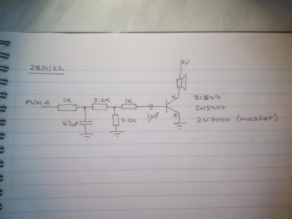 And assuming you correct my schematic will any of those transistors do the job ? Apologies for needing spoon-feeding on this; I was learning some basic electronics but then got hijacked by the Colour Maximite about a month in. Best wishes, Tom MMBasic for Linux, Game*Mite, CMM2 Welcome Tape, Creaky old text adventures |
||||
| matherp Guru Joined: 11/12/2012 Location: United KingdomPosts: 11548 |
The manual is sort-of correct except that we don't have the syntax for the real situation which is that one of dutyA or dutyB is manadatory but it doesn't have to be dutyA like in other MMBasic versions. I think this is explained in the text of the latest version. To drive the buzzer you really want to use an H bridge so that it sees +/- 5V |
||||
| Volhout Guru Joined: 05/03/2018 Location: NetherlandsPosts: 5950 |
First post has some contradicting information. - it is a piezo buzzer - it is 16 ohm Typically piezo buzzers I know are capacitors. They are high impedance. And you can drive them from a microprocessor pin (although this is risky) without a serial resistor. But if you have a multimeter, and measure Ohm, you hear a click at touching the piezo electrodes, and the meter measures infinite (high impedance). When the buzzer is a loudspeaker (wound coil around a magnet) and you measure it with a multimeter (ohms) the meter shows a low value (i.e. 10 ohm), and you may (or may not) hear a click sound. This type of buzzer you need a buffer transistor (or FET) to drive the coil. You cannot drive it from a picomite pin directly. MIXTEL90's circuit (or yours Tom) will not work. A transistor cannot be biased from a capacitor. You need resistors connected to the base of the transistor. I hope this helps... Volhout Edited 2022-11-29 00:21 by Volhout PicomiteVGA PETSCII ROBOTS |
||||
| thwill Guru Joined: 16/09/2019 Location: United KingdomPosts: 4369 |
Hi @Volhout, Are you saying the AliExpress listing may not have been entirely accurate - shock! It's one of these (though maybe not from this specific listing): https://www.aliexpress.com/i/3256801296478138.html?gatewayAdapt=4itemAdapt. I've measured a few and they are around the 17 ohm mark with no click (that I can hear). I assume you mean it is inadvisable, since using the PWM command I was able to do exactly that. Note both Mick and Peter have mentioned 5V, these are listed as 3V/3.3V ??? Best wishes, Tom Edited 2022-11-29 00:44 by thwill MMBasic for Linux, Game*Mite, CMM2 Welcome Tape, Creaky old text adventures |
||||
| Volhout Guru Joined: 05/03/2018 Location: NetherlandsPosts: 5950 |
The data from the Aliexpress page looks to specify a 2700Hz buzzer operated from 2-5Vdc pulling 40mA current. So you need not drive it from a PWM. It will generate 2700Hz if you connect it to 3.3V. And it will draw 40mA. You only need a IO pin and a FET or transistor to drive it ON and OFF. Quick check: connect + pin to 3.3V and - pin to GND... and shiver... Driver circuit (will work with 5V and 3.3V) 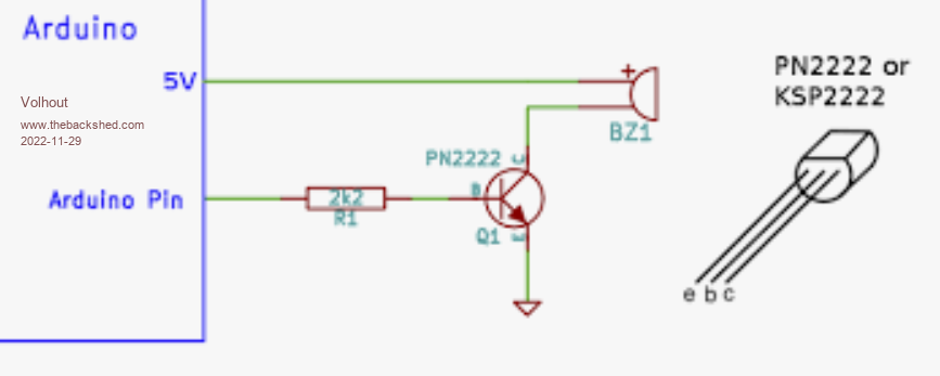 Edited 2022-11-29 02:23 by Volhout PicomiteVGA PETSCII ROBOTS |
||||
| thwill Guru Joined: 16/09/2019 Location: United KingdomPosts: 4369 |
MMBasic for Linux, Game*Mite, CMM2 Welcome Tape, Creaky old text adventures |
||||
| thwill Guru Joined: 16/09/2019 Location: United KingdomPosts: 4369 |
Now I'm just wholly confused as you seem to be suggesting it is an active buzzer, not a passive buzzer "... a 2700Hz buzzer operated from 2-5Vdc pulling 40mA current. So you need not drive it from a PWM." Tom Edited 2022-11-29 03:07 by thwill MMBasic for Linux, Game*Mite, CMM2 Welcome Tape, Creaky old text adventures |
||||
| Mixtel90 Guru Joined: 05/10/2019 Location: United KingdomPosts: 8913 |
If it's an active buzzer it's got a fixed frequency. It's either on or off. Have a close look and see if there's a + mark on it. Stick it on 3V and see if it makes a buzz. Mick Zilog Inside! nascom.info for Nascom & Gemini Preliminary MMBasic docs & my PCB designs |
||||
| thwill Guru Joined: 16/09/2019 Location: United KingdomPosts: 4369 |
I literally just tested it as you were writing that post. It does have a (+) but other than a brief crackle when you make the initial connection it doesn't do anything with 3.3V attached to it. Plus I drove it using PWM directly from a Pico pin earlier in the day and lived to tell the tale. I guess I'm going to proceed on the basis it is passive and later this evening try driving it though a 2.2K resistor to the base of a 2N3904. EDIT: and they are also slightly magnetic so I guess that means they are likely to be miniature speakers. Best wishes, Tom Edited 2022-11-29 03:26 by thwill MMBasic for Linux, Game*Mite, CMM2 Welcome Tape, Creaky old text adventures |
||||
| phil99 Guru Joined: 11/02/2018 Location: AustraliaPosts: 3295 |
An experiment. Wire it up as per Volhout's active buzzer circuit, but feed it with unfiltered audio from PLAY SOUND. The inductance of the coil plus mechanical inertia will provide some filtering and the 44.1kHz carrier is inaudible anyway. |
||||
| thwill Guru Joined: 16/09/2019 Location: United KingdomPosts: 4369 |
OK, so they are active buzzers and they work fine (with PWM) using Volhout's circuit from above with the PN2222 swapped out with the BC547s that I have. I even played a 2-channel version of "The Entertainer" on a pair of them using the PWM command, it was an experience not to be forgotten  . .But I get Sweet FA (with or without the low pass filter from the PicoMite manual) if I use the same setup with OPTION AUDIO, and PLAY TONE or PLAY SOUND. What detail am I failing to grasp ? Edit: I'm guessing it is something to do with the phrase in the manual "... �relies on capacitor coupling into the following amplifier ..." Best wishes, Tom Edited 2022-11-29 10:03 by thwill MMBasic for Linux, Game*Mite, CMM2 Welcome Tape, Creaky old text adventures |
||||
| phil99 Guru Joined: 11/02/2018 Location: AustraliaPosts: 3295 |
The average voltage on the Pico pin should be about 1.65V and the frequency 44.1kHz even with no modulation. If you can get that measure V and f on the base and collector. I would expect the average readings to be 0.3V B-E and 2.5V C-E with �44.1kHz on both. "Edit: I'm guessing it is something to do with the phrase in the manual "... relies on capacitor coupling into the following amplifier ..."" That is for a "proper" linear audio amplifier. This simple circuit is a "Class D" digital amplifier and relies on the DC component in the Pico output to forward bias the B-E junction. A capacitor would block that and require additional components. Edited 2022-11-29 10:07 by phil99 |
||||
| thwill Guru Joined: 16/09/2019 Location: United KingdomPosts: 4369 |
Deleted duplicate post Edited 2022-11-29 09:55 by thwill MMBasic for Linux, Game*Mite, CMM2 Welcome Tape, Creaky old text adventures |
||||
| thwill Guru Joined: 16/09/2019 Location: United KingdomPosts: 4369 |
I have the worlds worst DSO (the wife downvoted investing in a good one until my 50th birthday) and with OPTION AUDIO GP0,GP1 configured and no sound being played I am seeing a square(ish) wave at ~11.2 KHz and a Vavr of 1.45V on GP0 & GP1. With a sound nominally playing the peaks and troughs pulse horizontally which is presumably the result of the "audio signal superimposed" ? Remember I know nothing about any of this  . .Anyway, it's goodnight from Blighty, Best wishes, Tom MMBasic for Linux, Game*Mite, CMM2 Welcome Tape, Creaky old text adventures |
||||
| phil99 Guru Joined: 11/02/2018 Location: AustraliaPosts: 3295 |
Cross posted with an edit to my previous post. The frequency seems odd but it still should work. Try measuring with a multimeter frequency range. (some only go to 20kHz so check its specs.) I will have a go at it later. Later. > OPTION AUDIO 4, 5 > PLAY TONE 440, 1000 > Feeding into the one transistor circuit with a 16 ohm speaker it works well. With a multimeter Pico output 1.57V @ 40.08kHz B-E 430mV @ 40.08kHz C-E 4.1V @ 40.08kHz Edited 2022-11-29 10:55 by phil99 |
||||
| Page 1 of 4 |
|||||
| The Back Shed's forum code is written, and hosted, in Australia. | © JAQ Software 2026 |
