
|
|
Forum Index : Microcontroller and PC projects : PicoMite: driving a passive buzzer
| Author | Message | ||||
TassyJim Guru Joined: 07/08/2011 Location: AustraliaPosts: 6269 |
What you are seeing is the pico setting the no-signal level to VCC/2 to avoid the clicks when audio starts/stops. 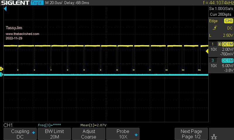 44.1kHz with the duty cycle changing to give the audio. I think you do need to filter it to minimise the 44.1 kHz. Jim Edited 2022-11-29 11:57 by TassyJim VK7JH MMedit |
||||
| Turbo46 Guru Joined: 24/12/2017 Location: AustraliaPosts: 1639 |
Tom, If Volhout's circuit is working then I would stick with that. The transistor is used to increase the drive capacity of the output pin. It is just switching 0's and 1's to the 'speaker', the speaker is effectively filtering out the high frequencies that it can't reproduce. Using filter circuits and series capacitors won't work because using them you are feeding a switching transistor circuit with an analogue signal. The transistor is not used as an audio amplifier, its a switch and analogue signals below about 0.6 volts won't turn it on. To use the filtered output, you need a more sophisticated audio amplifier circuit. The series capacitor mentioned in the manual would be something like: 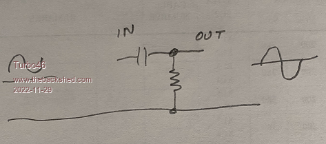 That would be used to remove the DC offset in the audio for an external audio amplifier that does not have series capacitor in it's input circuit. If the amplifier was DC coupled through to the speaker then it would have DC through the speaker and they would release the magic smoke. As to the problem with the 'OPTION AUDIO, and PLAY TONE or PLAY SOUND' I don't know. Bill Keep safe. Live long and prosper. |
||||
| Volhout Guru Joined: 05/03/2018 Location: NetherlandsPosts: 5058 |
What is FA ? When you use the OPTION AUDIO GPx,GPy on the picomite VGA, it starts a 44kHz (not 11kHz) square wave output on GPx and GPy. When no other command is give this is a steady signal. When you PLAY a WAV file the 44kHz is modulated (meaning the waveform changes in narrower and wider pulses, maintaining the 44kHz (same frequency, it just looks different). Similar when you PLAY TONE. I have no idea why this would behave different. But... The simple audio interface you have will give sound, but it will not give good sound. If you want good sound from this loudspeaker, I suggest you implement my audio amplifier/buffer (yes this requires breadboarding, or soldering) consiting of filter to remove the 44kHz. 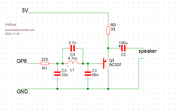 This is also the filter used in the VGA picomite. Added is a buffer (BC327) to drive the low impedance loudspeaker. The transistor is a PNP transistor. PicomiteVGA PETSCII ROBOTS |
||||
| JohnS Guru Joined: 18/11/2011 Location: United KingdomPosts: 4038 |
|
||||
| thwill Guru Joined: 16/09/2019 Location: United KingdomPosts: 4302 |
Hi folks, Thanks for the input, I must be doing something fundamentally daft when it comes to using OPTION AUDIO, but I won't be able to investigate further until tonight. In the meantime can anyone definitively answer the following (ignoring audio quality which is apparently an obsession with a significant number of electronic engineers  ). ).Should the same circuit (2.2K resistor feeding into base of NPN transistor) that will play sound using SETPIN GP#, PWM## and the corresponding raw PWM command also play sound using PLAY TONE ? Best wishes, Tom Edited 2022-11-29 18:54 by thwill MMBasic for Linux, Game*Mite, CMM2 Welcome Tape, Creaky old text adventures |
||||
| matherp Guru Joined: 11/12/2012 Location: United KingdomPosts: 10240 |
Not in any useful way. The Play tone equivalent program is something like: PWM 44100,50,50 SETTICK 1000/44100,myint 'play a 400Hz tone t=0 sub myint t=t+1/44100 'calculate the sine of the tone at time t x=sin(rad((t/400*360)) pwm 44100,50+(x*40) end sub Looking at the data for your buzzer on AliExpress it is a passive device with a resonant frequency of 2700Hz so to get optimum sound you should use PWM 2700,50 This could be fed through a transistor but to get maximum sound through an H-bridge PS your scope is presumably one of the little LCD versions? You are seeing sample aliasing if it is reading 11KHz (actual divided by 4) Edited 2022-11-29 19:25 by matherp |
||||
| Turbo46 Guru Joined: 24/12/2017 Location: AustraliaPosts: 1639 |
If you look further down to the frequency response, you will see the thing will produce sounds from 200Hz to 10,000 Hz. There is a peak at about 2700Hz so that is where it sounds loudest (the resonant frequency), but it will produce audio, nowhere near hifi but as I said before if it plays 'the entertainer' to your satisfaction then that's OK. I see no reason that the other methods of producing sound should not work. Bill Keep safe. Live long and prosper. |
||||
| thwill Guru Joined: 16/09/2019 Location: United KingdomPosts: 4302 |
This is very frustrating, I imagine for some of you too, it's clear I have fundamental misunderstanding  . .But at least that is explained. In layman's terms does that mean the DSO simply can't sample fast enough to read a 44 kHz signal? OK ... are you saying that PLAY TONE (and presumably PLAY SOUND) sends a constant frequency PWM signal @44100 Hz (outside of the range of human hearing) and encodes the actual tone by varying the duty cycle. Then presumably (in the absence of anything else I can see) the "low pass filter" given in the manual (and variations thereof produced by @Volhout and others) is responsible for decoding and recovering the tone ? However I think you are also telling me that the filter in the manual won't work when I want to drive these little buzzers via this simple transistor circuit ? @Volhout is the circuit you posted immediately above a suitable replacement filter (and driver) ... unfortunately it requires an inductor which is not something I have accumulated yet. Yes, there is nothing wrong with it except at the moment I am having to drive it via the raw PWM command and thus if I want 3 channel sound for example I need 3 buzzers and 3 PWM pins. Best wishes, Tom Edited 2022-11-29 20:19 by thwill MMBasic for Linux, Game*Mite, CMM2 Welcome Tape, Creaky old text adventures |
||||
| Turbo46 Guru Joined: 24/12/2017 Location: AustraliaPosts: 1639 |
Ah, the thot plickens, you didn't say that you wanted to use three channels. You could probably use three simple filters and feed them into Volhout's emitter follower circuit as a 'summing' input and drive your speaker that way if it is loud enough. As an emitter follower, it doesn't amplify the signal so you may need something more sophisticated. Bill Keep safe. Live long and prosper. |
||||
| thwill Guru Joined: 16/09/2019 Location: United KingdomPosts: 4302 |
No, no, no, just ignore the 3 channel problem. I can't get any channels out of PLAY TONE / SOUND at the moment. Motto for TBS, "We were never able to walk past a side-track." Best wishes, Tom Edited 2022-11-29 20:47 by thwill MMBasic for Linux, Game*Mite, CMM2 Welcome Tape, Creaky old text adventures |
||||
| matherp Guru Joined: 11/12/2012 Location: United KingdomPosts: 10240 |
The 44100Hz variable duty PWM used by the audio is a completely standard way of using PWM to create a DAC. To get the analogue output you then need to filter out the high frequency (same as a class D amplifier). What you are then left with is a varying analogue voltage. To feed a loudspeaker (you buzzer is a primitive loudspeaker with a catastrophic frequency response) you then need an amplifier to beef up the analogue signal. This must be capable of an analogue response - not a simple switch which is what your circuit is - see Volhout's circuit above for a working version. Note the frequency response of your buzzer shows a 15db drop in output from 2700Hz to 1500Hz. This is a difference in sound output of about 30x for an equivalent input!!!!!!!!! Edited 2022-11-29 21:05 by matherp |
||||
| phil99 Guru Joined: 11/02/2018 Location: AustraliaPosts: 2610 |
The simple one transistor circuit, without filter, works well. I tried it earlier. https://www.thebackshed.com/forum/ViewTopic.php?TID=15362&P=1#194562 It does not sound horrible, not hi-fi but as good as a tiny speaker can sound. |
||||
| thwill Guru Joined: 16/09/2019 Location: United KingdomPosts: 4302 |
For a moment things made sense ... and then they didn't again. Best wishes, Tom MMBasic for Linux, Game*Mite, CMM2 Welcome Tape, Creaky old text adventures |
||||
| thwill Guru Joined: 16/09/2019 Location: United KingdomPosts: 4302 |
OK, that's beginning to make sense, except for the bit where @phil99 says it works without a filter. I'll build and try with @Volhout's circuit, turns out I do have the right inductor from when I didn't get around to building the PicoGAME 2.0. Though it does seem like a lot of audio circuitry for a simple handheld game so may just use raw PWM - are there downsides other than the single channel and crappy noise ? Doesn't matter, I'm just prototyping, probably eventually upgrade to a laptop speaker from AliExpress. Thanks, Tom MMBasic for Linux, Game*Mite, CMM2 Welcome Tape, Creaky old text adventures |
||||
| Volhout Guru Joined: 05/03/2018 Location: NetherlandsPosts: 5058 |
No inductors, try this .... 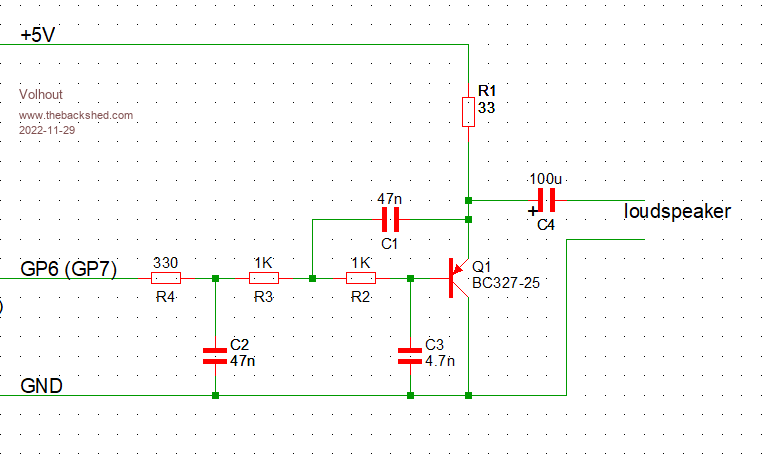 If you want to go cheap, remove C4, and connect the loudspeaker in stead of R1. But this may not be good for the speaker. Check: C3 is 4.7nf, C2 and C1 are 47nf (10x larger value). This will give you good audio up to 8 kHz (enough for game sounds). It is not as good as the inductor filter, but avoids the inductor. And (not a hot topic here, but it is in my profession) it can be fully SMT. So cheap to get assembled by JLCPCB or who-ever. Of coarse, if you want stereo, you need 2 of these. (as also with the previous design). If you avoid any filter, it will generally upset cats and other animals the hear 44kHz. The 44kHz sound level is really high. If you connect to a HIFI amplifier, I would most certainly add the filter. In your hand held gaming toy, you may be able to do without a filter. The gameboy sounds of the 80's and 90's also got away with minimal filtering to the small toy speakers. Edited 2022-11-29 21:49 by Volhout PicomiteVGA PETSCII ROBOTS |
||||
| thwill Guru Joined: 16/09/2019 Location: United KingdomPosts: 4302 |
Thanks @Volhout. What is the distinction between the BC327 in your earlier circuit and the BC327-25 in the latest circuit ? And take the fun out of soldering SMD by hand, not on my watch ... well unless it is some ridiculous tiny pitch IC. Best wishes, Tom MMBasic for Linux, Game*Mite, CMM2 Welcome Tape, Creaky old text adventures |
||||
| Volhout Guru Joined: 05/03/2018 Location: NetherlandsPosts: 5058 |
BC327-25 / BC327 The "-25" indicates it is a part with a typical current gain (called "hfe") of 250x. Without the suffix you can get values from 100 to 400. Any will work in this application, but 250 is best. No difference, it is just a symbol from my electronics simulation package. You can use any PNP like BC327 BC328 2N2907 2N3904. Maybe even BC557 BC558 BC559 (these are not really as good as the BC327/BC328 in this application on harmonic distortion, tested them before, but they will work). You could even try BD136 / BD138 / BD140 (medium power transistors). Whatever PNP is in your toolbox. But for best performance the BC327... On the SMT. The CMM1 and CMM2 units typically had SMT parts pre-soldered. there was only adding through hole parts (i.e. connectors) to be hand soldered. If ever you would think of GAMEpicoVGA series production, I would definitely propose to go SMT. This is cheap, people only need add the pico and connectors, and maybe headers. And the unusual inductor is gone.... Volhout Edited 2022-11-29 22:04 by Volhout PicomiteVGA PETSCII ROBOTS |
||||
| thwill Guru Joined: 16/09/2019 Location: United KingdomPosts: 4302 |
I have a bucket of those, they're just Chinese "rubbish" so I don't know about any "-25". Best wishes, Tom MMBasic for Linux, Game*Mite, CMM2 Welcome Tape, Creaky old text adventures |
||||
| thwill Guru Joined: 16/09/2019 Location: United KingdomPosts: 4302 |
And we are back here again!  Without a filter PLAY TONE/SOUND aren't doing anything (but raw PWM is). My understanding (if it can be called that) is that @matherp is saying that I need the filter to recover the TONE/SOUND from the carrier wave modulation (or however this should be referred to). However @phil99 is saying he didn't need the filter. Best wishes, Tom Edited 2022-11-29 22:04 by thwill MMBasic for Linux, Game*Mite, CMM2 Welcome Tape, Creaky old text adventures |
||||
| Volhout Guru Joined: 05/03/2018 Location: NetherlandsPosts: 5058 |
Wait a moment..... You are saying PWM works, but PLAY SOUND and PLAY TONE do not work ? Not even when you use GP6 and GP7 as outputs ? (after OPTION SOUND GP6,GP7). With my picomite VGA, when I disconnect the filter, and connect the small headset to the RAW pins (GP6 to GND, or GP7 to GND) I hear a sound. On the other hand: But when I connect the headset between GP6 and GP7 then I hear nothing... Since the sound at GP6 and GP7 is the same unless I acively program different frequencies. Maybe you tried connecting between pins, and not from pins to ground..?? Volhout PicomiteVGA PETSCII ROBOTS |
||||
| The Back Shed's forum code is written, and hosted, in Australia. | © JAQ Software 2025 |
