
|
|
Forum Index : Microcontroller and PC projects : PIO explained PICOMITE
| Page 1 of 8 |
|||||
| Author | Message | ||||
| Volhout Guru Joined: 05/03/2018 Location: NetherlandsPosts: 5931 |
The RP2040 is a microcontroller around a dual ARM M0 core. The ARM cores can communicate with the outside world using peripherals. Many of these peripherals are common function blocks, such as TIMERS, I2C, SPI ADC's and individual Inputs and Outputs. The TIMERS are often used for PWM. MMBasic has it's dedicated way of dealing with the peripherals. Input and Output and PWM, I2C, SPI and ADC are well supported from the language. The RP2040 however has one peripheral that is not a common function block: the PIO. The PIO is something that the Raspberry Pi designers added to make the chip very versatile, since it can be freely configured. The PIO can manipulate IO pins of the RP2040 chip without any intervention of the ARM cores Each PIO has 4 state machines that can run simple programs to manipulate IO pins. Stating that: it can run programs. But not like a microprocessor. It has a very limitted instructions set, it cannot even increment a value or add 2 numbers. When the ARM (MMBasic) assigns a pin to the PIO, it looses direct control over that pin. The ARM has only limitted control over what the PIO does. The main interface between the PIO and the ARM are the FIFO's. And it can start/stop execution of each statemachine in the PIO (there is more, but that will come in a later chapter). Block diagram of a PIO: the 4 state machines and the FIFO's are shown. As is the access to the IO. 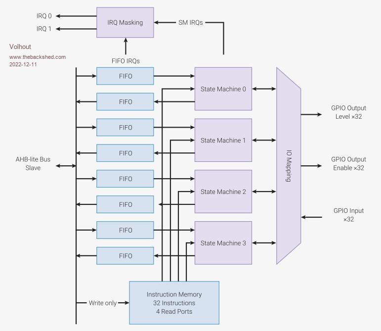 There is much documentation in the RP2040 datasheet (whole of chapter 3) on the PIO, that I often consult. You can find the datasheet on the Raspberry Pi web page. The RP2040 has 2 PIO blocks (so in total 8 state machines) but we will only experiment with PIO block 1, since PIO block 0 is used for generating VGA video in the VGA picomite ("boot to basic computer" on Geoff's website). And the VGA picomite is a perfect platform to learn through execersize. One thing the PIO has in common with MMbasic is that you need to provide 2 things: 1/ The configuration � (in normal MMbasic this is the OPTION list, and the SETPIN commands) � The PIO configuration from MMBasic uses the PIO INIT MACHINE command where it provides each state machine with the IO map and execution speed and other parameters (details later) MMBasic provides helper functions for the configuration. Many configuration parameters are defaulted in MMBasic, and we will use that. � 2/ The program � (in normal MMbasic this the the basic program, and occasionally the CSUB's). � Writing a program into the PIO uses the PIO PROGRAM command. MMBasic does not directly support Mnemonics (text describing the instruction) so we will manually create the hex codes that the PIO will execute. � Running the PIO program with PIO START, and stopping it with PIO STOP Above these commands can be executed inside the MMBasic program, so MMBAsic keeps control over the PIO's. Before we can configure a PIO state machine we need to know a bit about it's capabilities. We'll start with the simple things, and will dive deeper each post. IO The state machines can SET a pin high and low. They can shift serial data OUT and IN. The capaitals show the actual command... SET, OUT, IN. So IN does not read the state of a pin, it shifts a data bit IN. The shift in and shift out can shift multiple bits to equal number of SUCCESSIVE pins. A 32 bit FIFO value can be shifted out to 32 pins, making it a 32 bit write to IO. Finally the state machine can read the status of a pin (but there is not direct command for it). In the configuration you assign a number of pins to the state machine. As mentioned above, the state machine groups pins, so successive pins should be considered (i.e. SET output pins are GP1,GP2,GP3). There are configuration fields for IN, OUT, and SET (and SIDE SET, later more about this). You can assign the same pin for multiple functions (i.e. GP0 is used for OUT and SET, which is handy if you want to build a UART in PIO). The program for the complete PIO The statemachines execute 16 bit code. A PIO has 32 words (16 bit) of program memory. That program memory can be used for 1 state machine, but also for 2,3 or 4 state machines. They share program memory. One beautifull thing is that all 4 state machines can run the same program AT THE SAME TIME. In case you write a SPI output program, you essentially have 4 completely independent SPI outputs if you want. The state machines each have their own execution speed. Let's do out first program, start simple... blink (fast) Our first program is a LED blink program. The LED will blink very fast to keep things simple (666Hz) and in a later thread we will slow it down. We want the LED to connect to GP0. First we have to attach the GP0 pin to the PIO (PIO1 in this case). code SETPIN GP0,PIO1 Now the PIO must take control of the GP0 pin We want to be able to SET the GP0 pin high and SET the GP0 pin low to blink the LED. That is done in the pincontrol of PIO INIT MACHINE. There is a helper function for pincontrol: PINCTRL that has successive fields for : a/ the number of SIDE SET pins (not used here, but needs to be filled in, use 0) b/ the number of SET pins � � �(we used 1 pin, GP0, so this must be a 1) c/ the number of OUT pins � � �(not used here) d/ the lowest pin for IN pins �(not usede here) e/ the lowest pin for SIDE SET (not used here) f/ the lowest pin for SET � � �(must be set to GP0) g/ the lowest pin for OUT � � �(not used here) so PINCTRL (0,1,,,,gp0,) This tells the state machine there is 1 SET pin it can use, and the SET pin is GP0. If you change the "1" to a "2" the state machine can use GP0 and GP1 (2 succesive pins). Now we can start writing the PIO state machine program We want to do following �SET PIN to output label: �SET PIN HIGH �SET PIN LOW �GOTO LABEL � The state machines have a SET instruction: 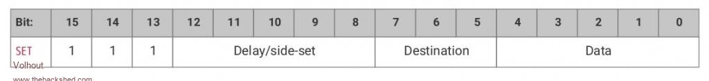 The instruction can SET up to 5 bits (the DATA field) in multiple destinations (DESTINATION field). One of them being the IO pins (DESTINATION = 000). The DELAY/SIDE SET field will be ignored for now (value 00000). More information about the SET instruction can be found in the RP2040 datasheet (chapter 3.4.10), which I highly recomend reading. So the instruction will read 111 00000 000 DATA Since we have 1 IO pin configured we can fill DATA with either 00000 (set pin to 0) or 00001 (set pin to 1). The other bits have no function with our configuration. In case we woudl assigne 2 IO pins, as hinted above, we could write 2 pins with 00000, 00010, 00001, 00011. Our program takes shape... 111 00000 000 00001 �= 1110 0000 0000 0001 = &hE001 �SET PIN HIGH 111 00000 000 00000 �= 1110 0000 0000 0000 = &hE000 �SET PIN LOW What about setting the pin to output mode... We use the same command. Only the DESTINATION field must be 100 to set the PIN DIRECTION to 1 111 00000 100 00001 �= 1110 0000 1000 0001 = &hE081 �SET PIN output Now we need to jump back to the beginning. Let us use the JMP instruction...  The instruction can under certain conditions to an absolute address (ADDRESS field). Since there are 5 bits in this field, and there are 32 program memory steps, we can jump directly everywhere. If we choose 000 for the CONDITION field, the jump is unconditional (always). The DELAY/SIDE SET field is ignored (00000). Now we only need to know the address. 000 00000 000 ADDRESS �&h0000+ADSRESS �JMP ADDRESS OK lets put this in PIO memory, starting at address line 0. LINE � CODE � � COMMENT 0 � � &hE081 � SET PIN OUT 1 � � &hE001 � SET PIN 1 2 � � &hE000 � SET PIN 0 3 � � &h0001 � JMP 1 � Finally we have to determine at what speed the state machine must run. The lowest frequency it can run at CPU speed 126MHz is 2kHz. So here we have our first program. We use state machine 0 of PIO 1. 'disconnect ARM from GP0 setpin gp0,pio1 'configure pio1 p=Pio(pinctrl 0,1,,,,gp0,) f=2000 'Hz 'pio program 'line � code �comment ' 0 � � E081 �GP0 output ' 1 � � E001 �pin high ' 2 � � E000 �pin low ' 3 � � 0001 �jmp 1 'program pio1 pio program line 0,&hE081 pio program line 1,&hE001 pio program line 2,&hE000 pio program line 3,&h0001 'write the configuration: PIO, state machine, frequency,pincontrol,,,start address PIO init machine 1,0,f,p,,,0 'start the pio1 code PIO start 1,0 An LED connected to GP0 will blink very fast (which appears a dim). Try this and play with it. Next time we will make some things simpler, and easier. Happy experimenting.... Volhout Edited 2022-12-11 09:33 by Volhout PicomiteVGA PETSCII ROBOTS |
||||
| KeepIS Guru Joined: 13/10/2014 Location: AustraliaPosts: 2177 |
This is a really nice clear informative write up. Thanks Volhout for putting in the time and effort. I'm sure this will inspire quite a few of the forum members who are not up to speed with the RP2040  Mike. NANO:Inverter V 8.2ks - Linux AvrDude GUI script V4.1 |
||||
Grogster Admin Group Joined: 31/12/2012 Location: New ZealandPosts: 9975 |
Agreed. Excellent tutorial information. I will be following this with much interest, as I would like to learn how to use the PIO's, but am too frightened of them right at the moment!  Smoke makes things work. When the smoke gets out, it stops! |
||||
| IanT Senior Member Joined: 29/11/2016 Location: United KingdomPosts: 130 |
Yes, very useful - thank you for making the effort. Regards, IanT |
||||
| Volhout Guru Joined: 05/03/2018 Location: NetherlandsPosts: 5931 |
The first chapter was a bit of dry because we needed to cover quite some ground. Next chapters will be smaller and contain less information. Will be more focusing on practice. So you will need a picomite, a breadboard of some kind (wires) and basic IO elements, such as some leds, a buzzer/piezo/speaker, resistors and switches. Speaking of buzzers. If you run previous exercise, connect a piezo/buzzer in stead of the LED to GP0, and experience the tone (666Hz). As to Grogster: don't be shy... the PIO code is loaded into RAM (program memory of the PIO), and will not damage your pico in any way. Just unplug and all is gone. The program in the first post will be used as a template for further exercises, each time modifying it a bit. For this who want to challenge themselves: try if you can get the same 666Hz tone out of pin GP2. Hint: you do not need to change the PIO program for that, just the configuration. In next chapter the solution will be given... Volhout Edited 2022-12-11 19:25 by Volhout PicomiteVGA PETSCII ROBOTS |
||||
| Pluto Guru Joined: 09/06/2017 Location: FinlandPosts: 411 |
Clear and bright  . Despite my very steep learning curve, I beleive I am still on track! . Despite my very steep learning curve, I beleive I am still on track!Now also the content of PR2040 datasheet chapter 3 starts to get a meaning. Looking forward to next chapter. |
||||
| Volhout Guru Joined: 05/03/2018 Location: NetherlandsPosts: 5931 |
As far as I can see ahead the next chapters will be: chapter 2 - explaining the exercise with pin configurations - explaining PIO INIT MACHINE - explaining PIO STOP - new: execution speed and 666Hz - new: DELAY field - new: ARM spying on PIO output - new exercise chapter 3 - explaining exercise solution - new: the SPY pin (PIO checking ARM I/O) - new: PIO PROGRAM versus PIO PROGRAM LINE - new exercise chapter 4 - explaining exercise solutions - new: variables X and Y - new exercise chapter 5 - explaining exercise solutions - new: FIFO and the ISR - new: measuring pulse width and transfer to MMBasic - new exercise chapter 6 - explaining exercise solutions - new: FIFO and OSR - new: generating pulse width commanded from MMBasic - new exercise chapter 7 - explaining exercise solutions - new: SIDE SET alternative to SET - new: controlling GP0 and GP22 in one state machines - new exercise chapter 8 - explaining exercise solutions - new: WRAP and WRAP TARGET replacing jump - new exercise chapter 9 - explaining exercise solutions - new: shifting IN data (SPI) - new: reading a NES controller in PIO - new exercise chapter 10 - explaining exercise solutions - new: shifting OUT data (SPI) - new: driving a 74HCT595 output shift register - new exercise Volhout PicomiteVGA PETSCII ROBOTS |
||||
| Grogster Admin Group Joined: 31/12/2012 Location: New ZealandPosts: 9975 |
SETPIN GP2,PIO1 ... p=Pio(pinctrl 0,1,,,,gp2,) ???????? Smoke makes things work. When the smoke gets out, it stops! |
||||
| Volhout Guru Joined: 05/03/2018 Location: NetherlandsPosts: 5931 |
Grogster, you are correct.! That is the simplest solution. PicomiteVGA PETSCII ROBOTS |
||||
| phil99 Guru Joined: 11/02/2018 Location: AustraliaPosts: 3291 |
You were testing us to make sure we were paying attention! 'disconnect ARM from GP2 SetPin GP2,pio1 'configure pio1 p=Pio(pinctrl 0,1,,,,GP2,) f=2000 'Hz 'pio program 'line � code �comment ' 0 � � E081 �GP2 output ' 1 � � E001 �pin high ' 2 � � E000 �pin low ' 3 � � 0001 �jmp 1 'program pio1 'PIO PROGRAM LINE pio, line,instruction PIO program line 1,0,&hE081 PIO program line 1,1,&hE001 PIO program line 1,2,&hE000 PIO program line 1,3,&h0001 'write the configuration: PIO, state machine, frequency,pincontrol,,,start address PIO init machine 1,0,f,p,,,0 'start the pio1 code PIO start 1,0 SetPin GP6,fin Pause 1000 Print Pin(gp6);" Hz from PIO1" Pause 5000 PIO stop 1,0 > option cpuspeed 126000 > RUN Produces the tone. PS �The subject of Chapter Ten got my attention. Have been playing with 74HC595s, driving with just 1 Pico pin Edited 2022-12-12 14:51 by phil99 |
||||
| Volhout Guru Joined: 05/03/2018 Location: NetherlandsPosts: 5931 |
Hi phil99 Your answer is correct. Nice addition to measure the frequency... The 1 pin drive of the 74hct595 can be included in chapter 10. I notice you always come up with elegant and efficient interface circuits. That I like. Volhout Edited 2022-12-12 16:45 by Volhout PicomiteVGA PETSCII ROBOTS |
||||
| Volhout Guru Joined: 05/03/2018 Location: NetherlandsPosts: 5931 |
chapter 2 - explaining the exercise with pin configurations Last chapters exercise was about moving the 666Hz tone from pin GP0 to GP2. You did not need to change the actual program, but only the configuration. The starting point was the GP0 configuration, that links GP0 to bit 0 of the SET command. 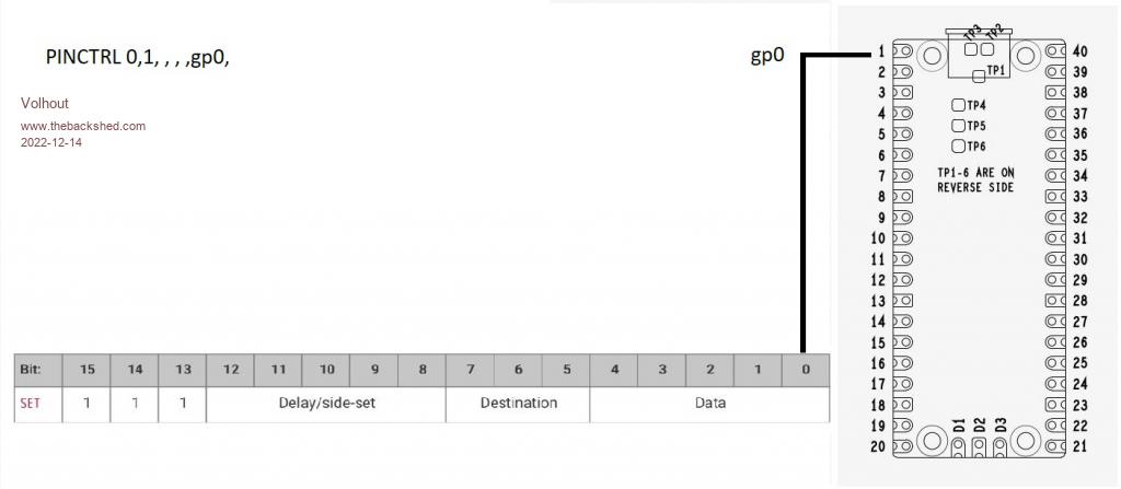 You can assign more pins to the SET command by increasing the number of successive pins 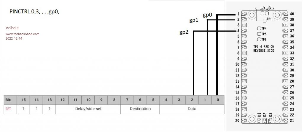 Or different pins, by selecting a different starting point 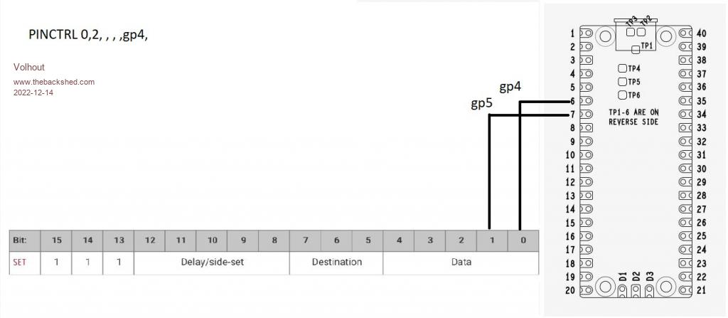 Knowing this the simplest answer is to assign 1 pin, named GP2. And of coarse, you need to assign GP2 to the PIO1 in a SETPIN in MMBasic. - explaining PIO INIT MACHINE The MMBasic command PIO INIT MACHINE writes the combined configuration values to the state machine. We have used the state machine frequency, and the state machine IO pin assignment (PINCTRL). But there are more configurations, that will be explained on further chapters. PIO INIT MACHINE a,b,c,d,e,f,g a/ the PIO (in our case PIO 1) b/ the state machine (0,1,2,3), we have used 0 in previosu exercise) c/ the state machine clock frequency (2000Hz in our previous exercise) d/ the pin control value (used in previous exersice to assigne GP0 to SET) e/ the execute control register (explanation will start in chapter 3 and 8) f/ the shift control register (will be explained in chapter 9 and 10) g/ the starting address of the program for this state machine (was 0 in our previous exercise) As you may have understood from the name PIO INIT MACHINE, each state machine needs it's won init. And has it's own PINCTRL and frequency. So one state machine can run at 2kHz, the other at 63MHz, both in the same PIO. And they can actually run the same code, just at different speed. But they can also run different code, depending the start address of the state machine. - explaining PIO STOP As you may have noticed when running the program in last chapter, the program ends, returns the comaand promt, but the audio tone from the PIO continued. That is the indication that the PIO operates independent of the ARM, and you need to force it to stop. note: Peter (MMBasic) stops the PIO when you edit the program or restart the program. The way to do that is PIO STOP a,b a/ the PIO b/ the state machine. - new: execution speed and 666Hz The state machine executes one program line in one clock cycle. The state machine in previous chapter was running at 2kHz (0.5ms). So if we analyze the program: LINE � CODE � � COMMENT 0 � � &hE081 � SET PIN OUT 0.5ms 1 � � &hE001 � SET PIN 1 0.5ms 2 � � &hE000 � SET PIN 0 0.5ms 3 � � &h0001 � JMP 1 � � � � �0.5ms After the SET PIN OUTPUT, the program runs a loop through adresses 1,2,3 then back to 1. A cytcle of 3 steps of 0.5ms. This makes the period of the output signal 1.5ms or 666Hz. But when we investigate what the GP0 pin is doing: LINE � CODE � � COMMENT 0 � � &hE081 � SET PIN OUT 0.5ms 1 � � &hE001 � SET PIN 1 0.5ms high 2 � � &hE000 � SET PIN 0 0.5ms � low 3 � � &h0001 � JMP 1 � � � � �0.5ms � no change -> low It is high 1/3 of the time, and low 2/3 of the time. That is not a nice square wave. For a nice 50% duty cycle we have the option to stretch the high level to 2 cycles. There are several options - new: DELAY field 1/ Add a dummy instruction (reapeat the same instruction, or add a NOP 0 � � &hE081 � SET PIN OUT 0.5ms 1 � � &hE001 � SET PIN 1 0.5ms high 2 � � &hE001 � SET PIN 1 0.5ms high, a dummy instruction 3 � � &hE000 � SET PIN 0 0.5ms � low 4 � � &h0001 � JMP 1 � � � � �0.5ms � no change -> low 2/ Add a delay of 1 clock cycle to the SET PIN 1 instruction. This is where the DELAY field of the SET instruction plays a role.  The delay field allows up to 31 (5 bits) clock cycles delay after the instruction is executed. If we want 1 extra clock cycle delay in the SET PIN 1 then this becomes 1 � � &hE101 � SET PIN 1, dly=1 1ms high �And out program looks like this: � LINE � CODE � � COMMENT 0 � � &hE081 � SET PIN OUT � � � �0.5ms 1 � � &hE101 � SET PIN 1 dly=1 � �1 ms � �high 2 � � &hE000 � SET PIN 0 � � � � �0.5ms � low 3 � � &h0001 � JMP 1 � � � � � � �0.5ms � no change -> low � Now we have a loop of 3 instructions, but 1 instruction lasts 2 cycles, so the loop is 2ms (500Hz). The frequency can be measured using the MMBasic frequency measurement function, as suggested by phil99. I used GP8 to do that since it matches my breadboard better. 'disconnect ARM from GP0 setpin gp0,pio1 'configure pio1 p=Pio(pinctrl 0,1,,,,gp0,) f=2000 'Hz 'pio program 'line � code �comment ' 0 � � E081 �GP0 output ' 1 � � E101 �pin high, dly=1 ' 2 � � E000 �pin low ' 3 � � 0001 �jmp 1 'program pio1 pio program line 1,0,&hE081 pio program line 1,1,&hE101 pio program line 1,2,&hE000 pio program line 1,3,&h0001 'write the configuration PIO init machine 1,0,f,p,,,0 'start the pio1 code PIO start 1,0 'Check the frequency in MMBasic Setpin GP8,FIN pause 1000 print pin(gp8);" Hz" PIO STOP 1,0 END - new: ARM spying on PIO output Peter has provided the possibility to let the ARM spy on PIO outputs. Normally you would get an erro message in case you try to read a pin that is assigned different, but for PIO he made an exemption. Since MMbasic is quite fast you can read the pin in a loop, and see the levels the PIO is putting out. From the output you can see that the duty cycle is 50% (as many 1's as there are 0's). 'disconnect ARM from GP0 setpin gp0,pio1 'configure pio1 p=Pio(pinctrl 0,1,,,,gp0,) f=2000 'Hz 'pio program 'line � code �comment ' 0 � � E081 �GP0 output ' 1 � � E101 �pin high, dly=1 ' 2 � � E000 �pin low ' 3 � � 0001 �jmp 1 'program pio1 pio program line 1,0,&hE081 pio program line 1,1,&hE101 pio program line 1,2,&hE000 pio program line 1,3,&h0001 'write the configuration PIO init machine 1,0,f,p,,,0 'start the pio1 code PIO start 1,0 ' check the GP0 pin from MMbasic 'array to store 101 samples taken from GP0 dim v%(100) 'sample the GP0 pin into the array 101 samples for i%=0 to 100 �v%(i%)=pin(gp0) �pause 0.1 � � � � � � 'limit the speed a bit next i% math v_print v%() � � � 'print the whole array to the screen 'stop pio PIO STOP 1,0 END RUN 0, 0, 0, 1, 1, 1, 1, 1, 1, 0, 0, 0, 0, 0, 0, 1, 1, 1, 1, 1, 1, 0, 0, 0, 0, 0, 0, 1, 1, 1, 1, 1, 1, 0, 0, 0, 0, 0, 0, 1,1 > > - new exercise Last time the exercise was pretty easy. This time we'll make 2 exercises, you can pick any you want, or both. They are about the current knwledge. #1: please adapt/write a program that outputs a nice 50Hz frequency from GP0. Note that the clock frequency for the PIO cannot go below 2kHz (at 126MHz CPUSPEED. #2: As you may have seen, Tom (thwill) bought buzzers that have a resonant frequency of 2.7kHz (they are most loud at that frequency). If this where a piezo, you need to drive it with high voltage level. This can be achieved by driving each pin of the piezo with a different IO pin. The second IO pin must be out of phase (180 degrees). This essentially is inverting the second pin. Happy programming..... Volhout Edited 2022-12-14 05:44 by Volhout PicomiteVGA PETSCII ROBOTS |
||||
| stanleyella Guru Joined: 25/06/2022 Location: United KingdomPosts: 2807 |
composite video out would be nice. |
||||
| Volhout Guru Joined: 05/03/2018 Location: NetherlandsPosts: 5931 |
I personally have not the skills to program that. But you may. Volhout PicomiteVGA PETSCII ROBOTS |
||||
| phil99 Guru Joined: 11/02/2018 Location: AustraliaPosts: 3291 |
50Hz, 50%. all else the same as 500Hz. 'pio program 'line code comment ' 0 E081 GP0 output ' 1 F301 pin high, dly=19 ' 2 F200 pin low, dly=18 ' 3 0001 jmp 1 'program pio1 PIO program line 1,0,&hE081 PIO program line 1,1,&hF301 PIO program line 1,2,&hF200 PIO program line 1,3,&h0001 'Read freq. n=0 'Find the start of a cycle then count cycles in 1 Sec. Do While Pin(GP0) : Loop Do While Not Pin(GP0) : Loop Timer =0 Do While Timer<1000 Do While Pin(GP0) : Loop Do While Not Pin(GP0) : Loop Inc n Loop Print n;" Hz at GP0" |
||||
| Tinine Guru Joined: 30/03/2016 Location: United KingdomPosts: 1646 |
Hey this stuff is starting to look like we mere mortals can handle it Craig |
||||
| Volhout Guru Joined: 05/03/2018 Location: NetherlandsPosts: 5931 |
@phil99 Well done, excellent solution @Tinine That is what I also realized. There is a lot of smoke around the PIO, but it is not overly complex. I feel the main issue with it is that you cannot easily debug your code. And if we fix PASM, we can even write mnemonics. But that is also why this thread is trying to go slow. Try things, don't make big steps, since you can always fall back to known things. We can go much faster if we assume everybody has an oscilloscope to see the waveform(s). Edited 2022-12-14 17:49 by Volhout PicomiteVGA PETSCII ROBOTS |
||||
| phil99 Guru Joined: 11/02/2018 Location: AustraliaPosts: 3291 |
For #2 this is all I can manage. It works after a fashion but the phase shift is a little over 180 deg. SetPin gp0,pio1 SetPin gp1,pio1 p0=Pio(pinctrl 0,1,,,,gp0,) p1=Pio(pinctrl 0,1,,,,gp1,) f=2000 * 5.4 'Hz for 2700Hz out. 'pio program 'line code comment ' 0 E081 GP0 output ' 1 E101 pin high, dly=1 ' 2 E000 pin low ' 3 0001 jmp 1 'program pio1 PIO program line 1,0,&he081 PIO program line 1,1,&he100 PIO program line 1,2,&he001 PIO program line 1,3,&h0001 'write the configuration PIO init machine 1,0,f,p0,,,0 PIO init machine 1,1,f,p1,,,0 'start the pio1 code PIO start 1,0 Do While Pin(gp0) : Loop PIO start 1,1 'Check the frequency in MMBasic SetPin GP6,FIN Do Pause 1000 Print Pin(gp6);" Hz at GP6" Loop End All attempts to invert the output within the PIO program failed. . |
||||
| Volhout Guru Joined: 05/03/2018 Location: NetherlandsPosts: 5931 |
Hi phil99, You have found a good solution !! Having 2 state machines run identical code, and start the second machine 180 degrees out of phase (the Do While Pin(gp0):Loop waits for GP0 to get low, and then starts the ssecond state machine, that starts with a setting gp1 high). Excellent thinking. The phase error you see lies in 2 things: - the delay in executing the MMBasic "Do While" and "Start PIO", but more so the PIO instruction that sets the GP1 port output. That is one instruction (with a loop of 4 instructions long) giving 90 degrees phase error. You could improve that behaviour by increasing the clock for the PIO, and adding delay in all instructions except for the one that set's output. But the phase error will never vanish. The solution that you where originally trying (I guess) and that did not work is attached below as a ZIP. I do not want to "publish" the solution yet, to give others the chance to work on a solution. Unless they cannot resist, then they must unpack the ZIP. Without details from you I estimate you did not get any signal on GP1. That symptom will be explained in the next chapter, and will be the introduction for the PIO EXECUTE command...( lifting part of the vail).... 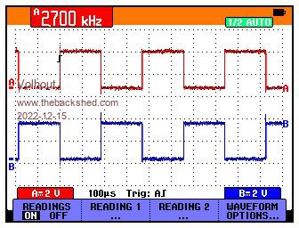 Volhout exercise_3_2.zip Edited 2022-12-15 20:56 by Volhout PicomiteVGA PETSCII ROBOTS |
||||
| phil99 Guru Joined: 11/02/2018 Location: AustraliaPosts: 3291 |
Thank you. That is far superior. The PicoMite manual doesn't go into the details and the RP2040 data sheet fries my tiny brain. " I estimate you did not get any signal on GP1" That was the main problem, but even if I had overcome that I couldn't see how to invert the second output. . Edited 2022-12-15 22:34 by phil99 |
||||
| Page 1 of 8 |
|||||
| The Back Shed's forum code is written, and hosted, in Australia. | © JAQ Software 2026 |
