
|
|
Forum Index : Microcontroller and PC projects : PIO explained PICOMITE
| Author | Message | ||||
| Volhout Guru Joined: 05/03/2018 Location: NetherlandsPosts: 5036 |
@manual: it might be good at end of this series, to re-look at the picomite manual and improve it. And it is on my wish list to make PASM/PREVAS work. I was unsuccesfull last time I tried it. For the training it is good to hand-assemble since (despite the fact that it is a bit more work) it gives better insight in what the PIO instructions do/can do. The RP2040 chapter on PIO contains a lot of information, but some of that information is written around the python and C environments, and yes, they confuse even the hell out of me. But the chapter on the assembly instructions (3.4) is important, and I directly use it every time I write code for PIO. I am curious if others show their results. I am very happy with your response, as it gives me energy to continue. Edited 2022-12-15 23:24 by Volhout PicomiteVGA PETSCII ROBOTS |
||||
| Volhout Guru Joined: 05/03/2018 Location: NetherlandsPosts: 5036 |
Since we had 2 exercises, and also new stuff to mention, chapter 3 is broken into 2 parts: 3.1: explaining the exercises 3.2: the new stuff (SPY pin, JMP, WAIT) This is 3.1 chapter 3 part 1 - exercise 1 explained To change the frequency to 50Hz (10ms low, 10ms high), with a fixed 2kHz clock frequency (0.5ms clock) you need (10/0.5 =) 20 instruction cycles high and 20 cyles low. In our basic program loop where we toggle GP0 this must be adapted line code comment 1 � E001 Set GP0 high -> add 19 cycles delay 2 � E000 Set GP0 low �-> add 18 cycles delay (jmp is also 1 cycle) 3 � jmp 1 These bits have to be added in the DELAY field (refer to the picture in chapter 1 or chapter 2 on the SET command. Set GP0 high, dly=19 = 111 10011 000 00001 = 1111 0011 0000 0001 = &hF301 Set GP0 low, dly=18 �= 111 10010 000 00000 = 1111 0010 0000 0000 = &hF200 So the program changes to line code �comment 1 � F301 �Set GP0 high, dly=19 2 � F200 �Set GP0 low, dly=18 3 � 0001 �jmp 1 Let's execute that .... success 'disconnect ARM from GP0 SetPin gp0,pio1 'configure pio1 p=Pio(pinctrl 0,1,,,,gp0,) f=2000 'Hz 'pio program 'line � code �comment ' 0 � � E081 �GP0 output ' 1 � � F301 �pin high, dly=19 ' 2 � � F200 �pin low,dly=18 ' 3 � � 0001 �jmp 1 'program pio1 PIO program line 1,0,&hE081 PIO program line 1,1,&hF301 PIO program line 1,2,&hF200 PIO program line 1,3,&h0001 'write the configuration PIO init machine 1,0,f,p,,,0 'start the pio1 code PIO start 1,0 - exercise 2 explained To change the frequency to 2700Hz and drive a second IO pin in counterphase (inverted) we have to make 2 adaptations 1/ change the PIO frequency to the correct value. Since we have a loop that generates the output signal, and we know that loop, we can calculate the PIO frequency. Let's take our 500Hz program as a basis. That program used a 2kHz clock to generate 500Hz, it has 4 instructions in the loop. To make that program output 2700Hz, the PIO clock frequency needs to be 2700Hz * 4. f = 2700 * 4 'Hz 2/ we have to drive a second GPIO pin (i.e. GP1) to output the inverted signal. We set the GP1 signal low, when we set GP0 high, and vice versa. If you look at the SET command, you see that we can SET multiple pins (up to 5). We only have to include GP1 into the SET map, and it's control ends up in the SET command. Adding GP1 to the SET map (GP1 is the next pin up from GP0) is done through PINCTRL. PINCTRL 0,2,,,,GP0, <--- 2 pins, starting from GP0 are assigned to this state machine. The program needs to SET both pins. GP0 is bit 0 in the SET command, GP1 is bit 1 in the SET command, refer to chapter 2 Set GP0 high, GP1 low, dly=1 = 111 00001 000 00001 = 1110 0001 0000 0001 = &hE101 Set GP0 low, GP1 high � � � �= 111 00000 000 00010 = 1110 0000 0000 0010 = &hE002 So our total program looks like: 'solution exercize chapter 3_2 'disconnect ARM from GP0 SetPin gp0,pio1 SetPin gp1,pio1 'configure pio1 p=Pio(pinctrl 0,2,,,,gp0,) f=2700 * 4 'Hz 'pio program 'line � code �comment ' 0 � � E083 �gp0 output ' 1 � � E101 �pin gp0 high, gp1 low, dly=1 ' 2 � � E002 �pin gp0 low, gp1 high ' 3 � � 0001 �jmp 1 'program pio1 PIO program line 1,0,&hE081 PIO program line 1,1,&hE101 PIO program line 1,2,&hE002 PIO program line 1,3,&h0001 'write the configuration PIO init machine 1,0,f,p,,,0 'start the pio1 code PIO start 1,0 Does it work ..... NO..... Why ? we did everything right, right ?? Oops...no, there is no signal on GP1.... The problem is that we changed the loop to set 2 pins. But we forgot to set GP1 to output (the instruction at line 0). That is also a SET command, and it should set GP1 output (bit 1 must become high). So line 0 should read: 0 �E083 � Set gp0 out, gp1 out And we can adapt the program.... but let's do it different this time. It is time for something new..... In the program, but also on the command line, you can force a state machine to execute an instruction that is not part of it's program memory. Our program is (still) busy generating 2700 Hz at gp0 pin and gp1 pin, but we can't see gp1 since it is not an output. At any time we can change that pin to output (even in a running PIO program) by: PIO EXECUTE a,b,c a/ PIO b/ state machine c/ Instruction So (at command line) we type: > PIO EXECUTE 1,0,&hE083 Voila.... we have both signals on gp1 and gp0... Now we have proven this is the solution, we can adapt our program. You can use PIO EXECUTE also in a MMBasic program. And when a PIO is configured, but no PIO program is programmed, you can prototype a program by just individually executing all statements. Like a simple form of single stepping. 'solution exercize chapter 3_2 'disconnect ARM from GP0 SetPin gp0,pio1 SetPin gp1,pio1 'configure pio1 p=Pio(pinctrl 0,2,,,,gp0,) f=2700*4 'Hz 'pio program 'line � code �comment ' 0 � � E083 �gp0,gp1 output ' 1 � � E101 �pin gp0 high, gp1 low, dly=1 ' 2 � � E002 �pin gp0 low, gp1 high ' 3 � � 0001 �jmp 1 'program pio1 PIO program line 1,0,&hE083 PIO program line 1,1,&hE101 PIO program line 1,2,&hE002 PIO program line 1,3,&h0001 'write the configuration PIO init machine 1,0,f,p,,,0 'start the pio1 code PIO start 1,0 'Check the frequency in MMBasic SetPin GP8,FIN Pause 1000 Print Pin(gp8);" Hz" PIO STOP 1,0 End Connect pin GP8 (the MMBasic frequency input) to either GP0 and GP1 to check the signal. Edited 2022-12-16 20:29 by Volhout PicomiteVGA PETSCII ROBOTS |
||||
| matherp Guru Joined: 11/12/2012 Location: United KingdomPosts: 10209 |
Please find attached the official pio assembler. This takes a pio source file and generates the hex together with the c commands that set up the pins etc. May be useful at least as far as getting the correct machine code for your source pioasm.zip 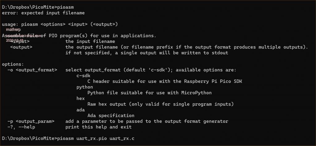 This is a command line executable (windows) example source file from Pico examples ; ; Copyright (c) 2020 Raspberry Pi (Trading) Ltd. ; ; SPDX-License-Identifier: BSD-3-Clause ; .program uart_rx_mini ; Minimum viable 8n1 UART receiver. Wait for the start bit, then sample 8 bits ; with the correct timing. ; IN pin 0 is mapped to the GPIO used as UART RX. ; Autopush must be enabled, with a threshold of 8. wait 0 pin 0 ; Wait for start bit set x, 7 [10] ; Preload bit counter, delay until eye of first data bit bitloop: ; Loop 8 times in pins, 1 ; Sample data jmp x-- bitloop [6] ; Each iteration is 8 cycles % c-sdk { #include "hardware/clocks.h" #include "hardware/gpio.h" static inline void uart_rx_mini_program_init(PIO pio, uint sm, uint offset, uint pin, uint baud) { pio_sm_set_consecutive_pindirs(pio, sm, pin, 1, false); pio_gpio_init(pio, pin); gpio_pull_up(pin); pio_sm_config c = uart_rx_mini_program_get_default_config(offset); sm_config_set_in_pins(&c, pin); // for WAIT, IN // Shift to right, autopush enabled sm_config_set_in_shift(&c, true, true, 8); sm_config_set_fifo_join(&c, PIO_FIFO_JOIN_RX); // SM transmits 1 bit per 8 execution cycles. float div = (float)clock_get_hz(clk_sys) / (8 * baud); sm_config_set_clkdiv(&c, div); pio_sm_init(pio, sm, offset, &c); pio_sm_set_enabled(pio, sm, true); } %} .program uart_rx ; Slightly more fleshed-out 8n1 UART receiver which handles framing errors and ; break conditions more gracefully. ; IN pin 0 and JMP pin are both mapped to the GPIO used as UART RX. start: wait 0 pin 0 ; Stall until start bit is asserted set x, 7 [10] ; Preload bit counter, then delay until halfway through bitloop: ; the first data bit (12 cycles incl wait, set). in pins, 1 ; Shift data bit into ISR jmp x-- bitloop [6] ; Loop 8 times, each loop iteration is 8 cycles jmp pin good_stop ; Check stop bit (should be high) irq 4 rel ; Either a framing error or a break. Set a sticky flag, wait 1 pin 0 ; and wait for line to return to idle state. jmp start ; Don't push data if we didn't see good framing. good_stop: ; No delay before returning to start; a little slack is push ; important in case the TX clock is slightly too fast. % c-sdk { static inline void uart_rx_program_init(PIO pio, uint sm, uint offset, uint pin, uint baud) { pio_sm_set_consecutive_pindirs(pio, sm, pin, 1, false); pio_gpio_init(pio, pin); gpio_pull_up(pin); pio_sm_config c = uart_rx_program_get_default_config(offset); sm_config_set_in_pins(&c, pin); // for WAIT, IN sm_config_set_jmp_pin(&c, pin); // for JMP // Shift to right, autopush disabled sm_config_set_in_shift(&c, true, false, 32); // Deeper FIFO as we're not doing any TX sm_config_set_fifo_join(&c, PIO_FIFO_JOIN_RX); // SM transmits 1 bit per 8 execution cycles. float div = (float)clock_get_hz(clk_sys) / (8 * baud); sm_config_set_clkdiv(&c, div); pio_sm_init(pio, sm, offset, &c); pio_sm_set_enabled(pio, sm, true); } static inline char uart_rx_program_getc(PIO pio, uint sm) { // 8-bit read from the uppermost byte of the FIFO, as data is left-justified io_rw_8 *rxfifo_shift = (io_rw_8*)&pio->rxf[sm] + 3; while (pio_sm_is_rx_fifo_empty(pio, sm)) tight_loop_contents(); return (char)*rxfifo_shift; } %} and the output // -------------------------------------------------- // // This file is autogenerated by pioasm; do not edit! // // -------------------------------------------------- // #pragma once #if !PICO_NO_HARDWARE #include "hardware/pio.h" #endif // ------------ // // uart_rx_mini // // ------------ // #define uart_rx_mini_wrap_target 0 #define uart_rx_mini_wrap 3 static const uint16_t uart_rx_mini_program_instructions[] = { // .wrap_target 0x2020, // 0: wait 0 pin, 0 0xea27, // 1: set x, 7 [10] 0x4001, // 2: in pins, 1 0x0642, // 3: jmp x--, 2 [6] // .wrap }; #if !PICO_NO_HARDWARE static const struct pio_program uart_rx_mini_program = { .instructions = uart_rx_mini_program_instructions, .length = 4, .origin = -1, }; static inline pio_sm_config uart_rx_mini_program_get_default_config(uint offset) { pio_sm_config c = pio_get_default_sm_config(); sm_config_set_wrap(&c, offset + uart_rx_mini_wrap_target, offset + uart_rx_mini_wrap); return c; } #include "hardware/clocks.h" #include "hardware/gpio.h" static inline void uart_rx_mini_program_init(PIO pio, uint sm, uint offset, uint pin, uint baud) { pio_sm_set_consecutive_pindirs(pio, sm, pin, 1, false); pio_gpio_init(pio, pin); gpio_pull_up(pin); pio_sm_config c = uart_rx_mini_program_get_default_config(offset); sm_config_set_in_pins(&c, pin); // for WAIT, IN // Shift to right, autopush enabled sm_config_set_in_shift(&c, true, true, 8); sm_config_set_fifo_join(&c, PIO_FIFO_JOIN_RX); // SM transmits 1 bit per 8 execution cycles. float div = (float)clock_get_hz(clk_sys) / (8 * baud); sm_config_set_clkdiv(&c, div); pio_sm_init(pio, sm, offset, &c); pio_sm_set_enabled(pio, sm, true); } #endif // ------- // // uart_rx // // ------- // #define uart_rx_wrap_target 0 #define uart_rx_wrap 8 static const uint16_t uart_rx_program_instructions[] = { // .wrap_target 0x2020, // 0: wait 0 pin, 0 0xea27, // 1: set x, 7 [10] 0x4001, // 2: in pins, 1 0x0642, // 3: jmp x--, 2 [6] 0x00c8, // 4: jmp pin, 8 0xc014, // 5: irq nowait 4 rel 0x20a0, // 6: wait 1 pin, 0 0x0000, // 7: jmp 0 0x8020, // 8: push block // .wrap }; #if !PICO_NO_HARDWARE static const struct pio_program uart_rx_program = { .instructions = uart_rx_program_instructions, .length = 9, .origin = -1, }; static inline pio_sm_config uart_rx_program_get_default_config(uint offset) { pio_sm_config c = pio_get_default_sm_config(); sm_config_set_wrap(&c, offset + uart_rx_wrap_target, offset + uart_rx_wrap); return c; } static inline void uart_rx_program_init(PIO pio, uint sm, uint offset, uint pin, uint baud) { pio_sm_set_consecutive_pindirs(pio, sm, pin, 1, false); pio_gpio_init(pio, pin); gpio_pull_up(pin); pio_sm_config c = uart_rx_program_get_default_config(offset); sm_config_set_in_pins(&c, pin); // for WAIT, IN sm_config_set_jmp_pin(&c, pin); // for JMP // Shift to right, autopush disabled sm_config_set_in_shift(&c, true, false, 32); // Deeper FIFO as we're not doing any TX sm_config_set_fifo_join(&c, PIO_FIFO_JOIN_RX); // SM transmits 1 bit per 8 execution cycles. float div = (float)clock_get_hz(clk_sys) / (8 * baud); sm_config_set_clkdiv(&c, div); pio_sm_init(pio, sm, offset, &c); pio_sm_set_enabled(pio, sm, true); } static inline char uart_rx_program_getc(PIO pio, uint sm) { // 8-bit read from the uppermost byte of the FIFO, as data is left-justified io_rw_8 *rxfifo_shift = (io_rw_8*)&pio->rxf[sm] + 3; while (pio_sm_is_rx_fifo_empty(pio, sm)) tight_loop_contents(); return (char)*rxfifo_shift; } #endif |
||||
| phil99 Guru Joined: 11/02/2018 Location: AustraliaPosts: 2593 |
Thanks, that will be very useful after I get a better understanding of the basics. Re last lesson, EXECUTE will be very handy for controlling the PIO. > PIO EXECUTE 1,0,&hE080 ' switch both off > PIO EXECUTE 1,0,&hE081 ' switch GP0 on > PIO EXECUTE 1,0,&hE082 ' switch GP0 off, GP1 on > PIO EXECUTE 1,0,&hE083 ' switch both on > |
||||
| Volhout Guru Joined: 05/03/2018 Location: NetherlandsPosts: 5036 |
General question: Is the information provided the correct level. I can go faster, or can go slower if needed, but someone has to tell me. Please respond. @phill99 I guess Peters post was to inform me, once I get to work on PASM and PREVAS. @Peter Thanks for the info. That is usefull. Question: PIO(PINCTRL ...) can use empty fields, and uses defaults (maybe accidentally 0, but it works). You can leave fields blank. PIO(EXECCTRL...) you have to fill in all fields, no defaults (wrap target = 0, wrap =&h1f), but also the first field (assign a pin) only accepts a number, not GPx. It would be logical is GPx was accepted as a first parameter. Is that fix-able ? Volhout PicomiteVGA PETSCII ROBOTS |
||||
| phil99 Guru Joined: 11/02/2018 Location: AustraliaPosts: 2593 |
Your current pace suits me, but if it is just a class of one the amount of work you are putting in is too much. Hello! Is There Anybody Out There? A half baked work in progress. 'PIO experiment - 50Hz 3 phase.bas 'disconnect ARM from GP0 - GP5 SetPin gp0,pio1 : SetPin gp1,pio1 SetPin gp2,pio1 : SetPin gp3,pio1 SetPin gp4,pio1 : SetPin gp5,pio1 'configure pio1 p0=Pio(pinctrl 0,2,,,,gp0,) p2=Pio(pinctrl 0,2,,,,gp2,) p4=Pio(pinctrl 0,2,,,,gp4,) f=2000 'Hz 'pio program 'line � code �comment ' 0 � � E083 �gp0,gp1 output ' 1 � � F301 �pin gp0 high, gp1 low, dly=19 ' 2 � � F202 �pin gp0 low, gp1 high, dly=18 ' 3 � � 0001 �jmp 1 'program pio1 Dim a%(7)=(&H0001f202f301E083,0,0,0,0,0,0,0) PIO program 1,a%() 'write the configuration PIO init machine 1,0,f,p0,,,0 PIO init machine 1,1,f,p2,,,0 PIO init machine 1,2,f,p4,,,0 'start the pio1 code PIO start 1,0 Pause 3.3 PIO start 1,1 Pause 3.3 PIO start 1,2 End Edited 2022-12-17 16:38 by phil99 |
||||
TassyJim Guru Joined: 07/08/2011 Location: AustraliaPosts: 6269 |
Watching and reading fully. I will start playing once a few life matters are out of the way. I was frightened of when I tried to read the official documentation so very pleased to have a clearer, more practical slant on things. Jim VK7JH MMedit |
||||
| Mixtel90 Guru Joined: 05/10/2019 Location: United KingdomPosts: 7832 |
Would you like me to make this into a manual, Volhout, so that it could be a PDF later? I've just been experimenting and I can copy the graphics ok so it should work. It would keep it "clean" from interjections. :) Mick Zilog Inside! nascom.info for Nascom & Gemini Preliminary MMBasic docs & my PCB designs |
||||
| Bleep Guru Joined: 09/01/2022 Location: United KingdomPosts: 624 |
Hi Volhout, Pace & detail all seem great from my perspective, I have dabbled in PIO b4 in C, but never got any further than driving a very long string of addressable LEDs so to have a simplified, broken down, how to is great. :-) Thanks for spending the time to do this, I know how long stuff like this can take. Keep up all your good work, I'm always �keen & �waiting for the next instalment. Regards Kevin PS. I might have a go @ driving those same LEDs again, but from PicoMIte, using your tutorial for guidance. :-) Edited 2022-12-17 18:37 by Bleep |
||||
| Volhout Guru Joined: 05/03/2018 Location: NetherlandsPosts: 5036 |
chapter 3.2 Up to now we have focussed on driving output signals from the PIO. But in many projects we would like the PIO to read inputs, to synchronize, or to change behaviour. Synchronize. A good way to synchronize is to WAIT until a input condition occurs, and then start executing. To evaluate the condition of a single input pin we can use the PIO WAIT instruction. 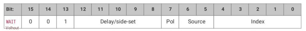 The fields have following function: DELAY/SIDE SET - we already know how to use the delay field. POL � � � � � �- the polarity of the input signal we wait for to become true (0/1) SOURCE � � � � - how to select a source. We use 00 so any GPIO pin can be checked. INDEX � � � � �- the pin number (i.e. 2 for GP2, 29 for gp29) The input pin does not need to be configured. That is easy. It does not even have to be detached from the ARM processor. You can spy on the ARM IO. Just read any single pin and wait for it's condition to happen. We can use that to start and stop the tonegenerator (500Hz). Somewhere in the loop we add the WAIT instruction to check if GP2 becomes high, and then continue with the loop. In pseudo code: label: wait gp2 to become high set pin gp0 high + delay 1 cycle set pin gp0 low jump to label The WAIT GP2=1 would assemble to WAIT gp2=1 �= 001 00000 100 00010 = 0010 0000 1000 0010 = &h2082 If you look at above pseudo code, you see that the gp0 pin is high 2 cycles, and low 3 cycles. For a nice square wave output, we should increase the delay with 1 cycle. in PIO code line code comment 0 � � E081 SET GP0 output 1 � � 2082 WAIT GP2=1 2 � � E201 � � SET gp0 high, dly=2 3 � � E000 � � SET gp0 low 4 � � 0001 � � JMP to 1 Now we can drive pin GP2 in MMBasc and switch the tone ON/OFF. Since we added an instruction, and a delay, out loop is now 6 cycles. The tone changes from 500Hz to 333Hz. We can change the frequency at which the PIO runs to correct that. For a 1 kHz tone, we set the PIO frequency to f=1000 * 6 ' 1000Hz output at 6 cycles loop. 'disconnect ARM from GP0 setpin gp0,pio1 'configure pio1 p=Pio(pinctrl 0,1,,,,gp0,) f=1000 * 6 'Hz 'line code comment ' 0 � � E081 SET GP0 output ' 1 � � 2082 WAIT GP2=1 ' 2 � � E201 � �SET gp0 high, dly=2 ' 3 � � E000 � �SET gp0 low ' 4 � � 0001 � �JMP to 1 'program pio1 pio program line 1,0,&hE081 pio program line 1,1,&h2082 pio program line 1,2,&hE201 pio program line 1,3,&hE000 pio program line 1,4,&h0001 'write the configuration PIO init machine 1,0,f,p,,,0 'start the pio1 code PIO start 1,0 'toggle GP2 in MMBasic Setpin gp2,dout do �pin(gp2) = 1 - pin(gp2) 'toggle pin GP2 �pause 100 loop END Change program flow WAIT is nice for synchronisation, but what if you wanted to make coffee when pin gp2 is high, and make tea when it is low. Not wait for a condition, but change your behaviour on a condition. The JMP instruction can be used for that. We have used the JMP instruction in previous examples as a non-conditional jump. But this instruction can be made conditional, and one of the conditions can be a single pin state.  CONDITION: when value is "110" the jump to ADDRESS will only occur when the pin is high. So a conditional JMP would assemble to JMP (pin=1),address = 000 00000 110 address = 0000 0000 1100 address = &h00Cx But the instruction has no field to assign a PIN (no bits left). The asignment of the pin pumber is done in a configuration value. In EXECCTRL. We have used PINCTRL before, and this is just another of those configuration values, So for WAIT you do not have to adapt the configuration But for conditional JMP you have to adapt the state machine configuration. Note: per state machine there is only 1 pin that can be assigned for conditional JMP. The new configuration value is EXECCTRL EXECCTRL a,b,c a/ This is the pin number we want to use for conditional jump, for gp2 set to 2 b/ wrap_target: this is not used now, set to 0 c/ wrap: this is not used now, set to 31 so for pin GP2 we would use EXECCTRL 2,0,31 We can use the conditional JMP to create a 2 tone siren, by just introducing a conditional extra delay. In pseudo code: label1: set pin gp0 high jmp (gp2=1) to label2 set pin gp0 high � � � � �<-------- this instruction will be skipped when GP2 high label2: set pin gp0 low jmp to label1 If we hand assemble this, it ends up as line code comment 0 � � E081 SET GP0 output 1 � � E001 � � SET gp0 high, dly=2 2 � � 00C4 JMP (GP2=1) to 4, (skip instruction 3) 3 � � E001 � � SET gp0 high 4 � � E000 � � SET gp0 low 5 � � 0001 � � JMP to 1 Out total program now becomes.... 'disconnect ARM from GP0 setpin gp0,pio1 'configure pio1 p=Pio(pinctrl 0,1,,,,gp0,) e=PIO(execctrl 2,0,31) f=1000 * 6 'Hz 'line code comment ' 0 � E081 SET GP0 output ' 1 � E001 � � SET gp0 high, dly=2 ' 2 � 00C4 JMP (GP2=1) to 4, (skip instruction 3) ' 3 � E001 � � SET gp0 high ' 4 � E000 � � SET gp0 low ' 5 � 0001 � � JMP to 1 'program pio1 pio program line 1,0,&hE081 pio program line 1,1,&hE001 pio program line 1,2,&h00C4 pio program line 1,3,&hE001 pio program line 1,4,&hE000 pio program line 1,5,&h0001 'write the configuration (note we added "e") PIO init machine 1,0,f,p,e,,0 'start the pio1 code PIO start 1,0 'toggle GP2 in MMBasic Setpin gp2,dout do �pin(gp2) = 1 - pin(gp2) 'toggle pin GP2 �pause 100 loop END We now have a 2 tone siren. Attach a beeper to GP0 and hear... The output signal is not a nice 50% duty cycles, but we have learned how to calculate the delays needed. I noticed phil99 is working on a PIO project (3 phase generator), and other have not answered with exercise proposals, so this time: no exercise. Edited 2022-12-17 18:45 by Volhout PicomiteVGA PETSCII ROBOTS |
||||
| JohnS Guru Joined: 18/11/2011 Location: United KingdomPosts: 4036 |
It's going at a good speed for me. I've been saving each one :) Thanks for the effort!! John |
||||
| circuit Senior Member Joined: 10/01/2016 Location: United KingdomPosts: 274 |
I am following this with great interest. Certainly excellent explanations and very much appreciated, thank you. Yes, your time is worthwhile -your post has over 1000 viewings...surely that shows that there is a LOT of interest in what you are teaching. Mick's offer to produce a manual would be well worthwhile, although I suspect it could go very nicely into the PicoMite Manual also. |
||||
| phil99 Guru Joined: 11/02/2018 Location: AustraliaPosts: 2593 |
"The output signal is not a nice 50% duty cycles, but we have learned how to calculate the delays needed." 'disconnect ARM from GP0. - 1000Hz / 1500Hz Square Wave SetPin gp0,pio1 'configure pio1 p=Pio(pinctrl 0,1,,,,gp0,) e=Pio(execctrl 2,0,31) f=1000 * 6 'Hz 'line code comment ' 0 E081 SET GP0 output ' 1 E001 SET gp0 high, dly=2 ' 2 00C4 JMP (GP2=1) to 5, (skip instructions 3 & 4) ' 3 E001 SET gp0 high ' 4 E000 SET gp0 low ' 5 E000 SET gp0 low ' 6 0001 JMP to 1 'program pio1 PIO program line 1,0,&hE081 PIO program line 1,1,&hE001 PIO program line 1,2,&h00C5 PIO program line 1,3,&hE001 PIO program line 1,4,&hE000 PIO program line 1,5,&hE000 PIO program line 1,6,&h0001 'write the configuration (note we added "e") PIO init machine 1,0,f,p,e,,0 'start the pio1 code PIO start 1,0 'toggle GP2 in MMBasic SetPin gp2,dout SetPin gp8,fin Do Pin(gp2) = Not Pin(gp2) 'toggle pin GP2 Print Pin(gp8) Pause 2000 Loop End |
||||
Grogster Admin Group Joined: 31/12/2012 Location: New ZealandPosts: 9588 |
@ phil99 & everyone else: Definitely watching/reading with interest. But as I know nothing about the PIO's really, I have to read and then re-read and then try some experiments before I would come up with any questions to ask.  Don't have much time at the moment, but once Christmas hits, the pressure will be off, and I can concentrate more on actually doing some of the things laid out in these lessons. +100 from me for Mick's offer to format this all into a manual. That is if Volhout does not want to do it, naturally. Smoke makes things work. When the smoke gets out, it stops! |
||||
| Volhout Guru Joined: 05/03/2018 Location: NetherlandsPosts: 5036 |
@phil99, Good solution ! And you did notice that you are already using 7 memory slots for such simple 2 tone siren. With only 32 memory locations for 4 state machines, you can imagine memory running out. I will adapt the course order of topics (learning on the job). In the next chapter we will discuss one method to make more compact code (wrap and wrap target). @Mick Yes, I would feel honoured in case you combine this knowledge in a user guide. Volhout Edited 2022-12-19 17:42 by Volhout PicomiteVGA PETSCII ROBOTS |
||||
| Tinine Guru Joined: 30/03/2016 Location: United KingdomPosts: 1646 |
A self contained MCU with a full-featured BASIC interpreter A mini-DOS The possibility to use C-subs/functions for time-critical code Now the possibility of determinism that runs independently of the main program Yeah, this is all amazing stuff....Nothing else like it  Craig |
||||
| Mixtel90 Guru Joined: 05/10/2019 Location: United KingdomPosts: 7832 |
OK, I'll carry on with my earlier experiment and polish it up a bit. I'll not keep releasing it as things progress as I think that might get even more confusing. :) However, once it gets to a reasonable size I'll start putting it in my Dropbox now and again. Mick Zilog Inside! nascom.info for Nascom & Gemini Preliminary MMBasic docs & my PCB designs |
||||
| Geoffg Guru Joined: 06/06/2011 Location: AustraliaPosts: 3282 |
This is great stuff. Mick, when you have it finished and ready I would like to add it to the "official" PicoMite(s) downloads - if that is OK with you and Volhout. Geoff Geoff Graham - http://geoffg.net |
||||
| Tinine Guru Joined: 30/03/2016 Location: United KingdomPosts: 1646 |
Another approach is a collaborative Google Docs file which would enable others to chip-in as this thing evolves. Craig |
||||
| Mixtel90 Guru Joined: 05/10/2019 Location: United KingdomPosts: 7832 |
That's fine with me, Geoff. Every little helps. :) Mick Zilog Inside! nascom.info for Nascom & Gemini Preliminary MMBasic docs & my PCB designs |
||||
| The Back Shed's forum code is written, and hosted, in Australia. | © JAQ Software 2025 |
