
|
|
Forum Index : Microcontroller and PC projects : Picomite VGA Logic analyzer
| Page 1 of 4 |
|||||
| Author | Message | ||||
| Volhout Guru Joined: 05/03/2018 Location: NetherlandsPosts: 5927 |
Hi All, As suggested by Peter, the logic analyzer project get's a new thread. Pluto: maybe this is of interest to you. PAN and SCAN (zoom and scoll) is working on the cursor keys. The trigger indication is not yet live, but you can set the trigger typing "t". Changing the sampling rate under UI control is next. Current focus is on: 1/ faster plotting 2/ trigger jitter '+----------------------------------------------------+ '| logic analyzer framework research program | '| | '| Volhout 20-1-2023 | '+----------------------------------------------------+ 'samples GP0...GP15 with triggering on GP22 'uses PIO and ring buffer under DMA. 'requires V50707b8 or newer (function names changed) '---------------------- version control ---------------- ' LA_3 uses DMA after manual trigger, serial output ' LA_4 uses DMA and ring buffer, serial output ' LA_5 testbed to debug DMA ' LA_6 restructure (this version) tbd PIO is ready ' LA_7 unroll circular buffer to linear array ' LA_8 triggering works ' LA_9 basic VGA display added ' LA_10 pan/scan added on cursor keys '-------------- prepare and init the picomite for LA --------------- generate_test_signal '--debug-- test signal PIO_prog 'program the PIO to sample samples% = 4096 'must be 2^x, larger than 256 init_memory 'set up data buffers init_trigger_config 'set up choice arrays set_screen 'set default screen parameters 'FRAMEBUFFER create 'FRAMEBUFFER write f '------------------------------ main loop ------------------------------- 'the new UI must be the type of 'default start and stop screen st%=0:sp%=samples%-1 Do aa$=Inkey$ ' read keyboard ' if "a" then arm DMA PIO ' if "<" then move centre, display ' if ">" then move centre, display ' if "^" then zoom in, display ' if "V" then zoom out, display ' if "t" then unarm, trigger setup ' if "s" then unarm, sample setup ' if PIO ready then update, display 'loop 'the old linear user interface ' Do 'decode trigger If aa$="t" Then Print @(0,0);"input trigger string (x/1/0) 6 characters for GP0..5 -or- CR" ; Input z$ If Len(z$)=6 Then setup_trigger_pattern EndIf EndIf 'pan/scan on cursor keys If aa$=Chr$(128) Then cp%=(sp%+st%)/2:rn%=(sp%-st%) rn%=Max(rn%/4,128) st%=cp%-rn%:sp%=cp%+rn% EndIf If aa$=Chr$(129) Then cp%=(sp%+st%)/2:rn%=(sp%-st%) st%=Max(cp%-rn%,0):sp%=Min(cp%+rn%,samples%-1) EndIf If aa$=Chr$(130) Then cp%=(sp%+st%)/2:rn%=(sp%-st%)/2 cp%=cp%-rn%/2 st%=Max(cp%-rn%,0):sp%=Min(cp%+rn%,samples%-1) EndIf If aa$=Chr$(131) Then cp%=(sp%+st%)/2:rn%=(sp%-st%)/2 cp%=cp%+rn%/2 st%=Max(cp%-rn%,0):sp%=Min(cp%+rn%,samples%-1) EndIf 'start la, wait for trigger arm_la 'calculate minimal circular buffer prefill time filltime%=Int(1000*3*length% / f0)+1 Pause filltime% 'fill pre-trigger buffer 'generate_trigger enable_trigger 'wait for trigger to happen Do Loop While Pin(gp22)=1 'the PIO should autocomplete, wait for post trigger length% written Pause filltime% 'fill post-trigger buffer 'stop DMA, this will call ReadyInt that stops the PIO and re-init it. PIO DMA RX OFF 'also unpacks the data 'display the data 'st%=0:sp%=samples%-1 scrnprint st%,sp% 'FRAMEBUFFER copy f,n,b Loop End '-----------------------------------SUBS MMBasic ------------------------------ 'convert the trigger string to PIO instructions for state machine 1 'program these instructions into pre-defined locations Sub setup_trigger_pattern For h%=1 To 6 For g%=0 To 2 If Mid$(z$,h%,1)=c$(g%) Then PIO program line 1,11+3*h%,p%(g%) 'program locations 14,17,....29 'print 11+3*h%,"&h";hex$(p%(g%)) EndIf Next g% Next h% End Sub 'start the trigger engine Sub enable_trigger PIO start 1,1 End Sub 'trigger characters related to PIO instructions Sub init_trigger_config Dim c$(2)=("x","1","0") Dim p%(2)=(&hE020,&h002A,&h004A) End Sub Sub set_screen MODE 1:Colour 0,RGB(WHITE):CLS :Font 7 Local f%,i% Dim a$(2)=("x","1","0") Dim tr(7)=(0,0,1,1,2,0,0,0) 'text For f%=0 To 7 Font 2:Print @(0,84+48*f%); f% Font 1:Print @(30,84+48*f%); "Channel";f% 'color TILE 0,5+f%*3,0,RGB(WHITE),7,2:TILE 7,5+f%*3,0,RGB(yellow),33,2 TILE 0,4+f%*3,0,RGB(midgreen),40,1 Line 0,64+f%*48,640,64+f%*48 'trigger boxes For i%=0 To 2 If tr(f%)=i% Then Box 34+i%*14,96+48*f%,16,16 EndIf 'trigger text Print @(38+i%*14,98+48*f%) a$(i%) Next i% Next End Sub 'unpack packed%() to unpacked%() such that trigger is in the centre Sub unroll varindex%=(Pio(DMA RX POINTER)-Peek(VARADDR packed%()))/8 'bytes -> 64bits beginsamples%=(Pio(DMA RX POINTER)-Peek(VARADDR packed%()))/4 'bytes -> 32b its 'beginsamples% = 2*varindex% endsamples% = samples% - beginsamples% Memory unpack Peek(varaddr packed%(varindex%)),unpacked%(),endsamples%,32 Memory unpack packed%(), Peek(varaddr unpacked%(endsamples%)),beginsamples%,3 2 End Sub 'when DMA is ready stop PIO's and re-init for next DMA, then unroll buffer Sub ReadyInt PIO STOP 1,0 PIO stop 1,1 PIO init machine 1,1,f1,p1,e1,s1,10 'start address = 10 (0x0A) PIO init machine 1,0,f0,p0,e0,s0,0 'start address = 0 unroll Math set 0,packed%() End Sub 'Start the DMA to accept FIFO data from PIO 1.0, and set the posttrigger value Sub arm_la 'the DMA will time out after &h7FFFFFFF samples, or when stopped PIO DMA RX 1,0,&h7FFFFFFF,packed%(),ReadyInt,32,samples% 'start DMA ring buff er 'write to PIO the number of post trigger samples, starts logging pre-trigger PIO WRITE 1,0,1,posttrigger% End Sub Sub init_memory 'define data buffers 'The logic analyzer captures samples% samples into the packed%() array' 'The DMA buffer has 64bit width, packed with 32bit FIFO (2 per cell) = length% 'The size of the ring buffer is specified in bytes, so size is 8 * length% 'the samples will be unpacked into unpacked%() at 32 bits per cell (=2*lenth%) posttrigger% = samples% / 2 'set trigger in centre of circular buffer data length% = samples% / 2 'packed buffer = 64bit, data buffer stores ' 32 bit (in 64 bit vars) Dim data%(samples%-1) 'array to put the 32 bit samples (base 0) Dim unpacked%(samples%-1) 'array to put the 32 bit samples (base 0) debug debug debug Dim packed% 'name of array to become circular buffer PIO MAKE RING BUFFER packed%,8*length% End Sub Sub generate_test_signal ' Test signal: Three phase motor drive - picomite V50706+ ' runs autonomously on GP0...GP5 50Hz SetPin gp0,pwm 'CH 0a SetPin gp1,pwm 'CH 0b SetPin gp2,pwm 'CH 1a SetPin gp3,pwm 'CH 1b SetPin gp4,pwm 'CH 2a SetPin gp5,pwm 'CH 2b PWM 0, 50, 11.11, -88.88, 1, 1 PWM 1, 49, 33.33, -66.66, 1, 1 PWM 2, 50, 33.33, -66.66, 1, 1 PWM sync 0, 100/3, 200/3 Pause 20 End Sub 'program the PIO with the sampler code (PIO 1.0) and the trigger 'framework (PIO 1.1) that is reprogrammed each time trigger is changed Sub PIO_prog 'assign GP22 (trigger_not) to PIO SetPin gp22,pio1 'the PIO 1.0 program: the sampler 'in this program the PIO reads GP0..GP5 brute force 'and pushes data into FIFO. The clock speed determines the 'sampling rate. There are 3 instructions per cycle 'address code mnemonics comment ' 0 E081 SET GP22 output '.wrap target ' 1 E001 SET GP22 high ' 2 80A0 pull block 'pull data from FIFO into OSR when avail ' 3 A027 mov(x,osr) 'load gate time (in PIO clocks) from osr ' 4 4006 IN pins 6 'read 6 pins ' 5 8000 PUSH noblock 'and push to FIFO ' 6 00C4 JMP (GP22) 4 'while no trigger (GP22=1) loop to 4 ' 7 4006 IN pins 6 'read 6 pins ' 8 8000 PUSH noblock 'and push to FIFO ' 9 0047 JMP (X<>0) 7 X-- 'while X<>0 decrement X and jump to 7 '.wrap 'clean start PIO clear 1 'program pio1.0 : sampler PIO program line 1,0,&hE081 PIO program line 1,1,&hE001 PIO program line 1,2,&h80A0 PIO program line 1,3,&hA027 PIO program line 1,4,&h4006 PIO program line 1,5,&h8000 PIO program line 1,6,&h00C4 PIO program line 1,7,&h4006 PIO program line 1,8,&h8000 PIO program line 1,9,&h0047 'program pio 1.1 : trigger engine 'since PIO does not know logic, we shift in bits, qualify each bit at a time 'this makes PIO trigger slow (21 instructions), so 300ns (f1=63MHz) is needed 'for guaranteed trigger detection 'address code mnemonics comment '.wrap target ' 10 4006 IN ISR 6 shift in the same data as the sampler ' 11 A0E6 MOV ISR->OSR mov data to shift out register ' 12 E020 clear X clear X register, prepare for new bit ' 13 6021 OUT OSR->X 1 shif 1 bit (GP0) into X register ' 14 E020 dummy will be re-programmed with cond. jump X ' 15 E020 clear X clear X register, prepare for new bit ' 16 6021 OUT OSR->X 1 shif 1 bit (GP1) into X register ' 17 E020 dummy will be re-programmed with cond. jump X 'etc... ' 27 E020 clear X clear X register, prepare for new bit ' 28 6021 OUT OSR->X 1 shif 1 bit (GP5) into X register ' 29 E020 dummy will be re-programmed with cond/ jump X ' 30 E000 SET GP22 low we passed all qualifiers -> trigger = OK '.wrap ' 31 000A JMP wrap targer not needed... 'program pio 1.1 : trigger engine PIO program line 1,10,&h4006 'IN ISR 6 PIO program line 1,11,&hA0E6 'MOV ISR->OSR PIO program line 1,12,&hE020 'clr X PIO program line 1,13,&h6021 'OUT OSR->X 1 PIO program line 1,14,&hE020 'trigger GP0 PIO program line 1,15,&hE020 'clr X PIO program line 1,16,&h6021 'OUT OSR->X 1 PIO program line 1,17,&hE020 'trigger GP1 PIO program line 1,18,&hE020 'clr X PIO program line 1,19,&h6021 'OUT OSR->X 1 PIO program line 1,20,&hE020 'trigger GP2 PIO program line 1,21,&hE020 'clr X PIO program line 1,22,&h6021 'OUT OSR->X 1 PIO program line 1,23,&hE020 'trigger GP3 PIO program line 1,24,&hE020 'clr X PIO program line 1,25,&h6021 'OUT OSR->X 1 PIO program line 1,26,&hE020 'trigger GP4 PIO program line 1,27,&hE020 'clr X PIO program line 1,28,&h6021 'OUT OSR->X 1 PIO program line 1,29,&hE020 'trigger GP5 PIO program line 1,30,&hE000 'set GP22 low PIO program line 1,31,&h000A 'jmp top 'configuration PIO 1.0 f0=4e4 'PIO run at 10kHz p0=Pio(pinctrl 0,1,0,gp0,,GP22,) 'IN base = GP0, SET = GP22 e0=Pio(execctrl gp22,1,9) 'wrap 9 to 1, gp22 is conditional JMP pin s0=Pio(shiftctrl 0,0,0,0,0,1) 'shift in through LSB, out is not used 'configuration PIO 1.1 f1=63e6 'PIO run at 63MHz p1=Pio(pinctrl 0,1,0,gp0,,GP22,) 'IN base = GP0, SET = GP22 e1=Pio(execctrl gp0,10,30) 'wrap 30 to 10 s1=Pio(shiftctrl 0,0,0,0,0,1) 'shift in through LSB, out through LSB 'write the configurations PIO init machine 1,0,f0,p0,e0,s0,0 'start address = 0 PIO init machine 1,1,f1,p1,e1,s1,10 'start address = 10 (0x0A) End Sub 'print the traces on the serial output Sub scrnprint st%,sp% 'print section st% to sp% of the linear array to serial (screen) Local z%,y%,x%,stp%,mask%,one%,eras%,bit% stp%=Int(0.5+(sp%-st%)/256) Timer =0 For j%=0 To 5 z%=j%*48+85 mask%=2^j% Box 112,z%-17,524,40,,1,1 'erase For i%=st% To sp% Step stp% bit%=((unpacked%(i%) And mask%)=0) one%=20*bit% 'Eras%=20*(1-bit%) x%=116+2*(i%-st%)/stp% y%=z%+one% 'Box x%,z%,2,21,,1,1 Line x%,y%,x%+2,y%,,0 'y%=z%+eras% 'Line x%,y%,x%+2,y%,,1 If i%=length% Then Box x%-4,z%-17,4,10 Next i% Next j% 'framebuffer copy f,n,b Print @(0,0) Timer End Sub > Edited 2023-01-27 22:29 by Volhout PicomiteVGA PETSCII ROBOTS |
||||
| matherp Guru Joined: 11/12/2012 Location: United KingdomPosts: 11499 |
I would suggest trigger at 10% or even better changeable |
||||
| Volhout Guru Joined: 05/03/2018 Location: NetherlandsPosts: 5927 |
Yes, can do. The code has a variable posttrigger% for that that is currently set to 50% default (sometimes you want to see what is causing trigger, sometimes you want to see result of trigger). Not sure if posttrigger% is implemented in all routines. I may have been cutting corners at places... But end goal is to have it configurable. P.S. with current array sizes (4096 samples), I cannot use framebuffer (despite 44k free, the 38k frame buffer does not fit). Need to check why. Should fit. Volhout Edited 2023-01-27 22:44 by Volhout PicomiteVGA PETSCII ROBOTS |
||||
| matherp Guru Joined: 11/12/2012 Location: United KingdomPosts: 11499 |
The code setting up the ringbuffer has to align it to a memory boundary that matches its size (limitation of the silicon). You need to assign it at an appropriate time relative to other variables/framebuffers to minimize the memory usage. Trial and error and peeking varaddr is the best approach I can suggest |
||||
| Volhout Guru Joined: 05/03/2018 Location: NetherlandsPosts: 5927 |
Intermediate version comment "generate_test_signal" out and you have a 6/8 channel LA on VGA you may want to disconnect and disable audio for channel 6 and 7 cleanup of code must happen trigger must be extended with edge trigger change: pan/scan with arrow cluster sampling rate with +/- trigger with t enjoy Volhout '+----------------------------------------------------+ '| � � logic analyzer framework research program � � �| '| � � � � � � � � � � � � � � � � � � � � � � � � � �| '| Volhout � � � � � � � � � � � � � � � � 20-1-2023 �| '+----------------------------------------------------+ 'samples GP0...GP15 with triggering on GP22 'uses PIO and ring buffer under DMA. 'requires V50707b8 or newer (function names changed) '---------------------- version control ---------------- ' LA_3 �uses DMA after manual trigger, serial output ' LA_4 �uses DMA and ring buffer, serial output ' LA_5 �testbed to debug DMA ' LA_6 �restructure (this version) tbd PIO is ready ' LA_7 �unroll circular buffer to linear array ' LA_8 �triggering works ' LA_9 �basic VGA display added ' LA_10 pan/scan added on cursor keys ' LA_11 8 chan, bar, sampling implemented '-------------- �prepare and init the picomite for LA --------------- �max_chan_no%=7 � � � � � � � � � � �'number of input channels �samples% = 4096 � � � � � � � � � � 'must be 2^x, larger than 256 �generate_test_signal � � � � � � � �'--debug-- test signal �PIO_prog � � � � � � � � � � � � � �'program the PIO to sample �init_memory � � � � � � � � � � � � 'set up data buffers �init_trigger_config � � � � � � � � 'set up choice arrays �init_sampling_rate � � � � � � � � �'different sampling rates �set_screen � � � � � � � � � � � � �'set default screen parameters �'FRAMEBUFFER create �'FRAMEBUFFER write f '------------------------------ main loop ------------------------------- 'the new UI must be the type of 'default start and stop screen st%=0:sp%=samples%-1 �'whole buffer frequency_index%=3 � �'10kHz Do � �aa$=Inkey$ ' � read keyboard ' � if "a" then arm DMA PIO ' � if "<" then move centre, display ' � if ">" then move centre, display ' � if "^" then zoom in, display ' � if "V" then zoom out, display ' � if "t" then unarm, trigger setup ' � if "s" then unarm, sample setup ' � if PIO ready then update, display 'loop 'the old linear user interface ' Do 'decode trigger If aa$="t" Then � �Print @(0,0);"input trigger string (x/1/0) 6 characters for GP0..5 -or- CR"; � �Input z$ � �If Len(z$)=6 Then � � �setup_trigger_pattern � �EndIf EndIf 'pan/scan on cursor keys If aa$=Chr$(128) Then � cp%=(sp%+st%)/2:rn%=(sp%-st%) � rn%=Max(rn%/4,64) � st%=cp%-rn%:sp%=cp%+rn% EndIf If aa$=Chr$(129) Then � cp%=(sp%+st%)/2:rn%=(sp%-st%) � st%=Max(cp%-rn%,0):sp%=Min(cp%+rn%,samples%-1) EndIf If aa$=Chr$(130) Then � cp%=(sp%+st%)/2:rn%=(sp%-st%)/2 � cp%=cp%-rn%/2 � st%=Max(cp%-rn%,0):sp%=Min(cp%+rn%,samples%-1) EndIf If aa$=Chr$(131) Then � cp%=(sp%+st%)/2:rn%=(sp%-st%)/2 � cp%=cp%+rn%/2 � st%=Max(cp%-rn%,0):sp%=Min(cp%+rn%,samples%-1) EndIf If aa$="+" Then �frequency_index%=Min(frequency_index%+1,13) �f0=sf%(frequency_index%) �Box 30,42,80,16,,0,1 � � � � � � 'full buffer �Print @(52,44) Right$(" � "+sr$(frequency_index%),6) EndIf If aa$="-" Then �frequency_index%=Max(frequency_index%-1,0) �f0=sf%(frequency_index%) �Box 30,42,80,16,,0,1 � � � � � � 'full buffer �Print @(52,44) Right$(" � "+sr$(frequency_index%),6) EndIf 'print zoom banner � �show_zoom 'start la, wait for trigger � �arm_la 'calculate minimal circular buffer prefill time � �filltime%=Int(1000*3*(samples%-posttrigger%)/f0)+10 � �Pause filltime% � � 'fill pre-trigger buffer 'generate_trigger � �enable_trigger 'wait for trigger to happen � �Do � �Loop While Pin(gp22)=1 'the PIO should autocomplete, wait for post trigger length% written � �filltime%=Int(1000*3*posttrigger%/f0)+10 � �Pause filltime% � �'fill post-trigger buffer 'stop DMA, this will call ReadyInt that stops the PIO and re-init it. � �PIO DMA RX OFF � � � � � � � � � � � � � � �'also unpacks the data 'display the data � �'st%=0:sp%=samples%-1 � �scrnprint st%,sp% � �'FRAMEBUFFER copy f,n,b �Loop End '-----------------------------------SUBS MMBasic ------------------------------ 'convert the trigger string to PIO instructions for state machine 1 'program these instructions into pre-defined locations Sub setup_trigger_pattern �For h%=1 To 6 � �For g%=0 To 2 � � �If Mid$(z$,h%,1)=c$(g%) Then � � � �PIO program line 1,11+3*h%,p%(g%) � � 'program locations 14,17,....29 'print 11+3*h%,"&h";hex$(p%(g%)) � � �EndIf � �Next g% �Next h% End Sub 'start the trigger engine Sub enable_trigger �PIO init machine 1,1,f1,p1,e1,s1,10 � 'start address = 10 (0x0A) �PIO start 1,1 End Sub 'trigger characters related to PIO instructions Sub init_trigger_config �Dim c$(4) length 2 = ("x","1","0","/","\") �'the instructions must be re-done in dynamic programming �Dim p%(4)=(&hE020,&h002A,&h004A,&hE020,&hE020) End Sub Sub init_sampling_rate �Dim sr$(13) length 8=("1kHz","2kHz","5kHz","10kHz","20kHz","50kHz","100kHz","200kHz","500kHz","1MHz","2MHz","5MHz","10MHz","21MHz") �Dim sf%(13)=(3e3,6e3,15e3,3e4,6e4,15e4,3e5,6e5,15e5,3e6,6e6,15e6,31e6,63e6) End Sub Sub set_screen �MODE 1:Colour 0,RGB(WHITE):CLS :Font 7 �Local f%,i% �Dim tr(7)=(4,0,1,1,2,0,0,0) 'text �For f%=0 To max_chan_no% � �Font 2:Print @(0,84+48*f%); f% � �Font 1:Print @(30,82+48*f%); "Channel";f% 'color � �TILE 0,0,0,RGB(yellow),40,4:TILE 0,27,0,RGB(white),40,3 � �TILE 0,5+f%*3,0,RGB(WHITE),7,2:TILE 7,5+f%*3,0,RGB(yellow),33,2 � �TILE 0,4+f%*3,0,RGB(midgreen),40,1 � �Line 0,64+f%*48,640,64+f%*48 'trigger boxes � �For i%=0 To 4 � � �If tr(f%)=i% Then � � � �Box 30+i%*14,96+48*f%,16,16 � � �EndIf 'trigger text � � �Print @(34+i%*14,98+48*f%) c$(i%) � �Next i% �Next End Sub 'unpack packed%() to unpacked%() such that trigger is in the centre Sub unroll �varindex%=(Pio(DMA RX POINTER)-Peek(VARADDR packed%()))/8 � 'bytes -> 64bits �beginsamples%=(Pio(DMA RX POINTER)-Peek(VARADDR packed%()))/4 � 'bytes -> 32bits �'beginsamples% = 2*varindex% �endsamples% = samples% - beginsamples% �Memory unpack Peek(varaddr packed%(varindex%)),unpacked%(),endsamples%,32 �Memory unpack packed%(), Peek(varaddr unpacked%(endsamples%)),beginsamples%,32 End Sub 'when DMA is ready stop PIO's and unroll buffer Sub ReadyInt �PIO STOP 1,0 �PIO stop 1,1 �unroll �Math set 0,packed%() End Sub 'Start the DMA to accept FIFO data from PIO 1.0, and set the posttrigger value Sub arm_la 'prepare the PIO 1.0 for new DMA �PIO init machine 1,0,f0,p0,e0,s0,0 � � 'start address = 0 'the DMA will time out after &h7FFFFFFF samples, or when stopped �PIO DMA RX 1,0,&h7FFFFFFF,packed%(),ReadyInt,32,samples% 'start DMA ring buffer 'write to PIO the number of post trigger samples, starts logging pre-trigger �PIO WRITE 1,0,1,posttrigger% End Sub Sub init_memory 'define data buffers 'The logic analyzer captures samples% samples into the packed%() array' 'The DMA buffer has 64bit width, packed with 32bit FIFO (2 per cell) = length% 'The size of the ring buffer is specified in bytes, so size is 8 * length% 'the samples will be unpacked into unpacked%() at 32 bits per cell (=2*lenth%) �posttrigger% = samples% / 2 � � � �'set trigger in centre of circular buffer data �length% = samples% / 2 � � � � � � 'packed buffer = 64bit, data buffer stores � � � � � � � � � � � � � � � � � � ' 32 bit (in 64 bit vars) �Dim data%(samples%-1) � � � � � � �'array to put the 32 bit samples (base 0) �Dim unpacked%(samples%-1) � � � � �'array to put the 32 bit samples (base 0) debug debug debug �Dim packed% � � � � � � � � � � � �'name of array to become circular buffer �PIO MAKE RING BUFFER packed%,8*length% End Sub Sub generate_test_signal ' Test signal: Three phase motor drive - picomite V50706+ ' runs autonomously on GP0...GP5 50Hz �SetPin gp0,pwm �'CH 0a �SetPin gp1,pwm �'CH 0b �SetPin gp2,pwm �'CH 1a �SetPin gp3,pwm �'CH 1b �SetPin gp4,pwm �'CH 2a �SetPin gp5,pwm �'CH 2b �PWM 0, 50, 11.11, -88.88, 1, 1 �PWM 1, 49, 33.33, -66.66, 1, 1 �PWM 2, 50, 33.33, -66.66, 1, 1 �PWM sync 0, 100/3, 200/3 �Pause 20 End Sub 'program the PIO with the sampler code (PIO 1.0) and the trigger 'framework (PIO 1.1) that is reprogrammed each time trigger is changed Sub PIO_prog 'assign GP22 (trigger_not) to PIO �SetPin gp22,pio1 'the PIO 1.0 program: the sampler 'in this program the PIO reads GP0..GP5 brute force 'and pushes data into FIFO. The clock speed determines the 'sampling rate. There are 3 instructions per cycle 'address � �code � �mnemonics � � � � comment ' �0 � � � �E081 � �SET GP22 output '.wrap target ' �1 � � � �E001 � �SET GP22 high ' �2 � � � �80A0 � �pull block � � � �'pull data from FIFO into OSR when avail ' �3 � � � �A027 � �mov(x,osr) � � � �'load gate time (in PIO clocks) from osr ' �4 � � � �4006 � �IN pins 6 � � � � 'read 6 pins ' �5 � � � �8000 � �PUSH noblock � � �'and push to FIFO ' �6 � � � �00C4 � �JMP (GP22) 4 � � �'while no trigger (GP22=1) loop to 4 ' �7 � � � �4006 � �IN pins 6 � � � � 'read 6 pins ' �8 � � � �8000 � �PUSH noblock � � �'and push to FIFO ' �9 � � � �0047 � �JMP (X<>0) 7 X-- �'while X<>0 decrement X and jump to 7 '.wrap 'clean start �PIO clear 1 'program pio1.0 : sampler �PIO program line 1,0,&hE081 �PIO program line 1,1,&hE001 �PIO program line 1,2,&h80A0 �PIO program line 1,3,&hA027 �PIO program line 1,4,&h4001+max_chan_no% �PIO program line 1,5,&h8000 �PIO program line 1,6,&h00C4 �PIO program line 1,7,&h4001+max_chan_no% �PIO program line 1,8,&h8000 �PIO program line 1,9,&h0047 'program pio 1.1 : trigger engine 'since PIO does not know logic, we shift in bits, qualify each bit at a time 'this makes PIO trigger slow (21 instructions), so 300ns (f1=63MHz) is needed 'for guaranteed trigger detection 'address � �code � �mnemonics � � � � comment '.wrap target ' �10 � � � 4006 � �IN ISR 6 � � � � �shift in the same data as the sampler ' �11 � � � A0E6 � �MOV ISR->OSR � � �mov data to shift out register ' �12 � � � E020 � �clear X � � � � � clear X register, prepare for new bit ' �13 � � � 6021 � �OUT OSR->X 1 � � �shif 1 bit (GP0) into X register ' �14 � � � E020 � �dummy � � � � � � will be re-programmed with cond. jump X ' �15 � � � E020 � �clear X � � � � � clear X register, prepare for new bit ' �16 � � � 6021 � �OUT OSR->X 1 � � �shif 1 bit (GP1) into X register ' �17 � � � E020 � �dummy � � � � � � will be re-programmed with cond. jump X 'etc... ' �27 � � � E020 � �clear X � � � � � clear X register, prepare for new bit ' �28 � � � 6021 � �OUT OSR->X 1 � � �shif 1 bit (GP5) into X register ' �29 � � � E020 � �dummy � � � � � � will be re-programmed with cond/ jump X ' �30 � � � E000 � �SET GP22 low � � �we passed all qualifiers -> trigger = OK '.wrap ' �31 � � � 000A � �JMP wrap targer � not needed... 'program pio 1.1 : trigger engine �PIO program line 1,10,&h4001+max_chan_no% � 'IN ISR 6/8 �PIO program line 1,11,&hA0E6 � � � � � � � �'MOV ISR->OSR �PIO program line 1,12,&hE020 � � � � � � � �'clr X �PIO program line 1,13,&h6021 � � � � � � � �'OUT OSR->X 1 �PIO program line 1,14,&hE020 � � � � � � � �'trigger GP0 �PIO program line 1,15,&hE020 � � � � � � � �'clr X �PIO program line 1,16,&h6021 � � � � � � � �'OUT OSR->X 1 �PIO program line 1,17,&hE020 � � � � � � � �'trigger GP1 �PIO program line 1,18,&hE020 � � � � � � � �'clr X �PIO program line 1,19,&h6021 � � � � � � � �'OUT OSR->X 1 �PIO program line 1,20,&hE020 � � � � � � � �'trigger GP2 �PIO program line 1,21,&hE020 � � � � � � � �'clr X �PIO program line 1,22,&h6021 � � � � � � � �'OUT OSR->X 1 �PIO program line 1,23,&hE020 � � � � � � � �'trigger GP3 �PIO program line 1,24,&hE020 � � � � � � � �'clr X �PIO program line 1,25,&h6021 � � � � � � � �'OUT OSR->X 1 �PIO program line 1,26,&hE020 � � � � � � � �'trigger GP4 �PIO program line 1,27,&hE020 � � � � � � � �'clr X �PIO program line 1,28,&h6021 � � � � � � � �'OUT OSR->X 1 �PIO program line 1,29,&hE020 � � � � � � � �'trigger GP5 �PIO program line 1,30,&hE000 � � � � � � � �'set GP22 low �PIO program line 1,31,&h000A � � � � � � � �'jmp top 'configuration PIO 1.0 �f0=4e4 � � � � � � � � � � � � � � 'PIO run at 10kHz �p0=Pio(pinctrl 0,1,0,gp0,,GP22,) � 'IN base = GP0, SET = GP22 �e0=Pio(execctrl gp22,1,9) � � � � �'wrap 9 to 1, gp22 is conditional JMP pin �s0=Pio(shiftctrl 0,0,0,0,0,1) � � �'shift in through LSB, out is not used 'configuration PIO 1.1 �f1=63e6 � � � � � � � � � � � � � �'PIO run at 63MHz �p1=Pio(pinctrl 0,1,0,gp0,,GP22,) � 'IN base = GP0, SET = GP22 �e1=Pio(execctrl gp0,10,30) � � � � 'wrap 30 to 10 �s1=Pio(shiftctrl 0,0,0,0,0,1) � � �'shift in through LSB, out through LSB 'write the default configurations �PIO init machine 1,0,f0,p0,e0,s0,0 � �'start address = 0 �PIO init machine 1,1,f1,p1,e1,s1,10 � 'start address = 10 (0x0A) End Sub 'print the traces on the serial output Sub scrnprint st%,sp% 'print section st% to sp% of the linear array to serial (screen) �Local z%,y%,x%,stp%,mask%,one%,eras%,bit% �stp%=Int(0.5+(sp%-st%)/128) �Timer =0 �For j%=0 To max_chan_no% � �z%=j%*48+85 � �mask%=2^j% � �Box 112,z%-17,524,14,,1,1 �'erase � �For i%=st% To sp% Step stp% � � �bit%=((unpacked%(i%) And mask%)=0) � � �one%=20*bit% � � �Eras%=20*(1-bit%) � � �x%=116+4*(i%-st%)/stp% � � �y%=z%+one% � � �'Box x%,z%,4,21,,1,1 � � �Line x%,y%,x%+4,y%,,0 � � �y%=z%+eras% � � �Line x%,y%,x%+4,y%,,1 � � �If i%=length% Then Print @(x%-4,z%-17) "T" ' � � �If i%=length% Then Box x%-4,z%-17,4,10 � �Next i% �Next j% �'framebuffer copy f,n,b �Print @(570,0) Timer End Sub 'show st%-sp% in relation to 0-samples% Sub show_zoom �Local stp% �Box 116,42,513,16,,0,1 � � � � � � 'full buffer �stp%=samples%/512 �Box 117+(st%/stp%),44,(sp%-st%)/stp%,12,,0,0 End Sub Edited 2023-01-28 19:21 by Volhout PicomiteVGA PETSCII ROBOTS |
||||
| matherp Guru Joined: 11/12/2012 Location: United KingdomPosts: 11499 |
Don't know if it is relevant for this application but the next beta will allow you to execute a PIO instruction from a CFunction (same functionality as the PIO EXECUTE command) and a CFunction can in turn be triggered by a H/W interrupt such as an edge triggered pin change. |
||||
| phil99 Guru Joined: 11/02/2018 Location: AustraliaPosts: 3289 |
Thanks Volhout this will be very useful. Displayed pulse widths seem to fluctuate a bit. 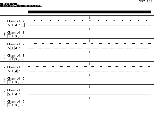 |
||||
| Volhout Guru Joined: 05/03/2018 Location: NetherlandsPosts: 5927 |
In this version, the display shows all samples when you zoom in maximum. When your sampling rate is 10kHz (100us) a signal of 120us can appear as 1 sample, 100us, or as 2 samples 200us. Depending on the exact moment of the first sample. To minimize this effect the trigger program runs fastest. This effect will be less if you sample faster (press + key few times.) When you zoom out, you will start seeing aliasing effects, since the display will show 1 in 4 or 1 in 8 samples. The LA samples 4096 samples, but shows only 128 or 256 at a time. I hope this explains a bit... Volhout P.s. if you have optio audio set, channel 6 and 7 will show aliasing signal of 44kHz. Only when you turn the samping up to 1MHz it makes any sense. At the moment you can not trigger on channel 6 and 7. Edited 2023-01-28 23:50 by Volhout PicomiteVGA PETSCII ROBOTS |
||||
| Volhout Guru Joined: 05/03/2018 Location: NetherlandsPosts: 5927 |
This is version 0.12 of the logic analyzer. It is a major re-write of the trigger engine. I have to put it through it's paces, but think it is functional enough. From here I hope the changes will be cosmetic. User interface: arrow keys zoom in and out, and move the visible window through the buffer with +/- you increase/decrease the sampling rate setting the trigger is still typing in a string of characters. Default setting now is for 8 channels, but you can change the value of maxh_chan_no% in line 25 (5=GP5, 7=GP7). todo: - trigger changes - nice top of screen graphics - programmable channel names future: - I2C decoder, SPI decoder, UART decoder '+----------------------------------------------------+ '| logic analyzer framework research program | '| | '| Volhout 20-1-2023 | '+----------------------------------------------------+ 'samples GP0...GP15 with triggering on GP22 'uses PIO and ring buffer under DMA. 'requires V50707b8 or newer (function names changed) '---------------------- version control ---------------- ' LA_3 uses DMA after manual trigger, serial output ' LA_4 uses DMA and ring buffer, serial output ' LA_5 testbed to debug DMA ' LA_6 restructure (this version) tbd PIO is ready ' LA_7 unroll circular buffer to linear array ' LA_8 triggering works ' LA_9 basic VGA display added ' LA_10 pan/scan added on cursor keys ' LA_11 8 chan, bar, sampling implemented ' LA_12 6/8 channel '-------------- prepare and init the picomite for LA --------------- max_chan_no%=7 'number of input channels samples% = 4096 'must be 2^x, larger than 256 st%=0:sp%=samples%-1 'whole buffer shown default frequency_index%=3 '10kHz deafult sampling speed generate_test_signal '--debug-- test signal PIO_prog 'program the PIO to sample init_memory 'set up data buffers init_trigger_config 'set up choice arrays init_sampling_rate 'different sampling rates set_screen 'set default screen parameters '------------------------------ main loop ------------------------------- Do if aa$="" then aa$=Inkey$ end if ' read keyboard ' if "<" then move centre, display ' if ">" then move centre, display ' if "^" then zoom in, display ' if "V" then zoom out, display ' if "t" then unarm, goto trigger setup ' if "+/-" then unarm, change sample setup ' if number then change channel name ' if PIO ready then update, display 'loop 'the old linear user interface ' Do 'decode trigger If aa$="t" Then Print @(0,0);"set trigger (x,1,0,/,\), type 1 char per GP pin"; Input z$ If Len(z$)=(1+max_chan_no%) Then setup_trigger_pattern EndIf EndIf 'pan/scan on cursor keys If aa$=Chr$(128) Then cp%=(sp%+st%)/2:rn%=(sp%-st%) rn%=Max(rn%/4,64) st%=cp%-rn%:sp%=cp%+rn% EndIf If aa$=Chr$(129) Then cp%=(sp%+st%)/2:rn%=(sp%-st%) st%=Max(cp%-rn%,0):sp%=Min(cp%+rn%,samples%-1) EndIf If aa$=Chr$(130) Then cp%=(sp%+st%)/2:rn%=(sp%-st%)/2 cp%=cp%-rn%/2 st%=Max(cp%-rn%,0):sp%=Min(cp%+rn%,samples%-1) EndIf If aa$=Chr$(131) Then cp%=(sp%+st%)/2:rn%=(sp%-st%)/2 cp%=cp%+rn%/2 st%=Max(cp%-rn%,0):sp%=Min(cp%+rn%,samples%-1) EndIf If aa$="+" Then frequency_index%=Min(frequency_index%+1,13) f0=sf%(frequency_index%) Box 30,42,80,16,,0,1 'full buffer Print @(52,44) Right$(" "+sr$(frequency_index%),6) EndIf If aa$="-" Then frequency_index%=Max(frequency_index%-1,0) f0=sf%(frequency_index%) Box 30,42,80,16,,0,1 'full buffer Print @(52,44) Right$(" "+sr$(frequency_index%),6) EndIf 'end of key decoding aa$="" 'print zoom banner show_zoom 'start la, wait for trigger arm_la 'calculate minimal circular buffer prefill time filltime%=Int(1000*3*(samples%-posttrigger%)/f0)+10 Pause filltime% 'fill pre-trigger buffer 'generate_trigger enable_trigger 'wait for trigger to happen print @(350,45) "ARMED" Do aa$=inkey$ Loop While Pin(gp22)=1 and aa$="" print @(350,45) "FIRED" 'the PIO should autocomplete, wait for post trigger length% written filltime%=Int(1000*3*posttrigger%/f0)+10 Pause filltime% 'fill post-trigger buffer 'stop DMA, this will call ReadyInt that stops the PIO and re-init it. PIO DMA RX OFF 'also unpacks the data 'display the data scrnprint st%,sp% Loop End '-----------------------------------SUBS MMBasic ------------------------------ 'convert the trigger string to PIO instructions for state machine 1 'program these instructions into pre-defined locations Sub setup_trigger_pattern For h%=0 To max_chan_no% For g%=0 To 4 If Mid$(z$,h%+1,1)=c$(g%) Then tr%(h%)=g% trigger_legend trigger_create_program 'if h%<6 then 'PIO program line 1,14+3*h%,p%(g%) 'program locations 14,17,....29 'end if EndIf Next g% Next h% End Sub 'start the trigger engine Sub enable_trigger PIO init machine 1,1,f1,p1,e1,s1,10 'start address = 10 (0x0A) PIO start 1,1 End Sub 'trigger characters related to PIO instructions Sub init_trigger_config Dim c$(4) length 2 = ("x","1","0","/","\") 'text for the 5trigger modes Dim tr%(max_chan_no%) 'trigger mode for all channels, default 0 'the instructions must be re-done in dynamic programming Dim p%(4)=(&hE020,&h002A,&h004A,&hE020,&hE020) End Sub 'relation between PIO clock and sampling rates Sub init_sampling_rate Dim sr$(13) length 8=("1kHz","2kHz","5kHz","10kHz","20kHz","50kHz","100kHz","200kHz","500kHz","1MHz","2MHz","5MHz","10MHz","21MHz") Dim sf%(13)=(3e3,6e3,15e3,3e4,6e4,15e4,3e5,6e5,15e5,3e6,6e6,15e6,31e6,63e6) End Sub 'initializes the screen (colors, font, lines) Sub set_screen MODE 1:Colour 0,RGB(WHITE):CLS :Font 1 'generic screeen setup from Martin H TILE 0,0,0,RGB(white),40,30 'default all tiles to correct background Local f%,i% 'indicate initial sampling speed Box 30,42,80,16,,0,1 'full buffer Print @(52,44) Right$(" "+sr$(frequency_index%),6) For f%=0 To max_chan_no% 'TILE 0,0,0,RGB(yellow),40,4 'top color ? t.b.decided TILE 0,5+f%*3,0,RGB(WHITE),7,2:TILE 7,5+f%*3,0,RGB(yellow),33,2 TILE 0,4+f%*3,0,RGB(midgreen),40,1:Line 0,64+f%*48,640,64+f%*48 Next f% 'posh for 6 channel mode TILE 0,22,0,RGB(midgreen),40,1:Line 0,352,640,352 channel_legend trigger_legend End Sub 'shows the trigger settings on screen sub trigger_legend local f%,i% For f%=0 To max_chan_no% 'for all channels Box 30,96+48*f%,71,16,,1,1 'erase all boxes and text For i%=0 To 4 'step through all 5 trigger modes If tr%(f%)=i% Then Box 30+i%*14,96+48*f%,16,16 'write current trigger boxes EndIf Print @(34+i%*14,98+48*f%) c$(i%) 're-write text Next i% Next f% end sub 'shows the channel names on screen sub channel_legend local f% For f%=0 To max_chan_no% Font 2:Print @(0,84+48*f%); f% Font 1:Print @(30,82+48*f%); "Channel";f% Next f% end sub 'unpack packed%() to unpacked%() such that trigger is in the centre Sub unroll varindex%=(Pio(DMA RX POINTER)-Peek(VARADDR packed%()))/8 'bytes -> 64bits beginsamples%=(Pio(DMA RX POINTER)-Peek(VARADDR packed%()))/4 'bytes -> 32bits 'beginsamples% = 2*varindex% endsamples% = samples% - beginsamples% Memory unpack Peek(varaddr packed%(varindex%)),unpacked%(),endsamples%,32 Memory unpack packed%(), Peek(varaddr unpacked%(endsamples%)),beginsamples%,32 End Sub 'when DMA is ready stop PIO's and unroll buffer Sub ReadyInt PIO STOP 1,0 PIO stop 1,1 unroll Math set 0,packed%() End Sub 'Start the DMA to accept FIFO data from PIO 1.0, and set the posttrigger value Sub arm_la 'prepare the PIO 1.0 for new DMA PIO init machine 1,0,f0,p0,e0,s0,0 'start address = 0 'the DMA will time out after &h7FFFFFFF samples, or when stopped PIO DMA RX 1,0,&h7FFFFFFF,packed%(),ReadyInt,32,samples% 'start DMA ring buffer 'write to PIO the number of post trigger samples, starts logging pre-trigger PIO WRITE 1,0,1,posttrigger% End Sub Sub init_memory 'define data buffers 'The logic analyzer captures samples% samples into the packed%() array' 'The DMA buffer has 64bit width, packed with 32bit FIFO (2 per cell) = length% 'The size of the ring buffer is specified in bytes, so size is 8 * length% 'the samples will be unpacked into unpacked%() at 32 bits per cell (=2*lenth%) posttrigger% = samples% / 2 'set trigger in centre of circular buffer length% = samples% / 2 'packed buffer = 64bit, data buffer 32bit Dim unpacked%(samples%-1) 'array to put the 32 bit samples (base 0) Dim packed% 'name of array to become circular buffer PIO MAKE RING BUFFER packed%,8*length% End Sub ' Test signal: Three phase motor drive - picomite V50706+ Sub generate_test_signal ' runs autonomously on GP0...GP5 50Hz SetPin gp0,pwm 'CH 0a SetPin gp1,pwm 'CH 0b SetPin gp2,pwm 'CH 1a SetPin gp3,pwm 'CH 1b SetPin gp4,pwm 'CH 2a SetPin gp5,pwm 'CH 2b PWM 0, 50, 11.11, -88.88, 1, 1 PWM 1, 49, 33.33, -66.66, 1, 1 PWM 2, 50, 33.33, -66.66, 1, 1 PWM sync 0, 100/3, 200/3 Pause 20 End Sub 'program the PIO with the sampler code (PIO 1.0) and the default trigger PIO 1.1 'PIO 1.1 is reprogrammed each time trigger is changed Sub PIO_prog 'assign GP22 (trigger_not) to PIO SetPin gp22,pio1 'the PIO 1.0 program: the sampler PIO reads GP0..GP7 brute force 'and pushes data into FIFO. The clock speed determines the 'sampling rate. There are 3 instructions per cycle 'after trigger (line 6) is detected "posttrigger%" samples are added to FIFO 'clean start PIO clear 1 'program pio1.0 : sampler PIO program line 1,0,&hE081 'SET GP22 output PIO program line 1,1,&hE001 'SET GP22 high PIO program line 1,2,&h80A0 'PULL block PIO program line 1,3,&hA027 'mov(x,osr) PIO program line 1,4,&h4001+max_chan_no% 'IN pins 6/8 PIO program line 1,5,&h8000 'PUSH noblock PIO program line 1,6,&h00C4 'JMP (GP22) 4 PIO program line 1,7,&h4001+max_chan_no% 'IN pins 6/8 PIO program line 1,8,&h8000 'PUSH noblock PIO program line 1,9,&h0047 'JMP (X<>0) 7 X-- 'initial trigger program: run continuous (set GP22 low) PIO program line 1,10,&hE000 'set GP22 low PIO program line 1,11,&h000B 'jmp always to itself 'configuration PIO 1.0 f0=4e4 'PIO run at 10kHz p0=Pio(pinctrl 0,1,0,gp0,,GP22,) 'IN base = GP0, SET = GP22 e0=Pio(execctrl gp22,1,9) 'wrap 9 to 1, gp22 is conditional JMP pin s0=Pio(shiftctrl 0,0,0,0,0,1) 'shift in through LSB, out is not used 'configuration PIO 1.1 f1=63e6 'PIO run at 63MHz p1=Pio(pinctrl 0,1,0,gp0,,GP22,) 'IN base = GP0, SET = GP22 e1=Pio(execctrl gp0,10,30) 'wrap 30 to 10 s1=Pio(shiftctrl 0,0,0,0,0,1) 'shift in through LSB, out through LSB 'write the default configurations PIO init machine 1,0,f0,p0,e0,s0,0 'start address = 0 PIO init machine 1,1,f1,p1,e1,s1,10 'start address = 10 (0x0A) End Sub 'print the traces on the serial output Sub scrnprint st%,sp% 'print section st% to sp% of the linear array to serial (screen) Local z%,y%,x%,stp%,mask%,one%,eras%,bit% stp%=Int(0.5+(sp%-st%)/128) Timer =0 For j%=0 To max_chan_no% z%=j%*48+85 mask%=2^j% Box 112,z%-17,524,14,,1,1 'erase For i%=st% To sp% Step stp% bit%=((unpacked%(i%) And mask%)=0) one%=20*bit% Eras%=20*(1-bit%) x%=116+4*(i%-st%)/stp% y%=z%+one% Line x%,y%,x%+4,y%,,0 y%=z%+eras% Line x%,y%,x%+4,y%,,1 If i%=length% and tr%(j%)<>0 Then Print @(x%-4,z%-17) "T" Next i% Next j% 'Print @(570,0) Timer End Sub 'show bar st%-sp% in relation to full range 0-samples% Sub show_zoom Local stp% Box 116,42,513,16,,0,1 'full buffer stp%=samples%/512 Box 117+(st%/stp%),44,(sp%-st%)/stp%,12,,0,0 End Sub 'from the tr%() array create the trigger program for PIO 1.1 sub trigger_create_program 'when there is an edge trigger, it is placed at start of the program 'after that the logic conditions are added 'there can be only 1 edge trigger in this engine, the first in string local trigger_start_address%, trigger_end_address%, i% trigger_start_address% = 10 'address &h0A trigger_end_address%= 31 'last location PIO program write_pio%=trigger_start_address% 'check edge trigger, for edge trigger use the PIO WAIT GPx instruction 'a falling edge is WAIT GPx=1, WAIT GPx=0. Rising edge WAIT GPx=0, WAIT GPx=1 for i%=0 to max_chan_no% if tr%(i%) > 2 then 'found edge trigger for channel i% 'below code can be optimized further if tr%(i%)=3 then 'rising edge inc_write_pio &h2000+i% inc_write_pio &h2080+i% else 'falling edge inc_write_pio &h2080+i% inc_write_pio &h2000+i% end if i%=max_chan_no% 'search no further, skip the rest end if next i% 'check the static conditions. This shifts data in the ISR, copies to OSR inc_write_pio &h4001+max_chan_no% 'IN ISR 6/8 inc_write_pio &hA0E6 'MOV ISR->OSR 'Each input processed by reading a new bit from OSR and checking it 'edge triggered pin is skipped (first one is processed, rest is ignored) for i%=0 to max_chan_no% select case tr%(i%) case 0,3,4 'x / \ do nothing, shift bit out into Y (not used) inc_write_pio &h6041 'OUT OSR->Y 1 case 1 '1 inc_write_pio &h6021 'OUT OSR->X 1 inc_write_pio &h002A 'trigger GPx=1 case 2 '0 inc_write_pio &h6021 'OUT OSR->X 1 inc_write_pio &h004A 'trigger GPx=0 end select next i% 'when all triggers are true, we set GP22 low as trigger for the sampler inc_write_pio &hE000 'set GP22 low inc_write_pio &h000A 'jmp top (needed when memory not full) 'print @(10,10) write_pio% ' maximum program length is: ' without edge trigger: 2 (shift in) + 8 * 2 (8 channels) + 2 (trigger+jump) = 20 ' with edge trigger: 2 (edge) + 2 (shift in) + 7 * 2 (7 remaining channels) ' + 1 (skipped edge) + 2 (trigger+jump) = 21 ' start addres = 10, end = 31 -> 21 will always fit. No check nor discard needed. end sub 'this programs 1 PIO line and advances to the next line sub inc_write_pio instr% pio program line 1,write_pio%,instr% inc write_pio%,1 end sub PicomiteVGA PETSCII ROBOTS |
||||
| Martin H. Guru Joined: 04/06/2022 Location: GermanyPosts: 1459 |
wow, good work  'no comment |
||||
| thwill Guru Joined: 16/09/2019 Location: United KingdomPosts: 4369 |
Hi Volhout, I've been following with interest, if little understanding. Can I anticipate a description of the hardware setup and a brief tutorial in the future? Best wishes, Tom MMBasic for Linux, Game*Mite, CMM2 Welcome Tape, Creaky old text adventures |
||||
| Volhout Guru Joined: 05/03/2018 Location: NetherlandsPosts: 5927 |
Of coarse. I guess 1 or 2 weeks to finalize the program, the I will issue a tutorial, also explaining how the pico digests the signals. PicomiteVGA PETSCII ROBOTS |
||||
| JohnS Guru Joined: 18/11/2011 Location: United KingdomPosts: 4335 |
Looks very interesting & the tutorial will hopefully really help. John |
||||
| thwill Guru Joined: 16/09/2019 Location: United KingdomPosts: 4369 |
Edited 2023-01-30 20:09 by thwill MMBasic for Linux, Game*Mite, CMM2 Welcome Tape, Creaky old text adventures |
||||
| Turbo46 Guru Joined: 24/12/2017 Location: AustraliaPosts: 1693 |
Why some listings like the one a few posts up showing question marks in a black diamond? It looks like the forum is censoring tab characters maybe? Bill Keep safe. Live long and prosper. |
||||
TassyJim Guru Joined: 07/08/2011 Location: AustraliaPosts: 6538 |
I expect it happened when Gizmo moved the forum. '2000' is one of those pesky space characters. Later and earlier posts don't have that problem. I can "fix" it for you required. Jim VK7JH MMedit |
||||
| Turbo46 Guru Joined: 24/12/2017 Location: AustraliaPosts: 1693 |
Thanks Jim, It's not important. I can replace them in the word processor but Notepad strangely won't find it as a single character but it will with a space before or after it? By the way it's also done it to your signature. Bill Keep safe. Live long and prosper. |
||||
| TassyJim Guru Joined: 07/08/2011 Location: AustraliaPosts: 6538 |
Easiest was is to copy it into a hex editor and do a global replace 00 to 20 Every thing seems to line up after that so I don't think there are any other oddities. I have fixed my sig. Jim VK7JH MMedit |
||||
| Pluto Guru Joined: 09/06/2017 Location: FinlandPosts: 411 |
Started to look at I2C decoding from data captured by Volhout's LA program. For testing purpose an ADT7410 temperature sensor was used. This is connected to an other PicoMite; the PicoMite running the LA is just tapping the I2C wires. The I2C decoder is just a SUB added to the end of Volhout's LA program. First run the LA and set the trigger to Channel 0 (I2C-clk). Channel 1 is I2C-data. Adjust the LA sampling rate. E.g. for 100kHz I2C the minimum sampling rate is 500kHz. Just stop the LA (ctrl-C) and clear screen (MMCC, Cls). Then: type I2C_decoded and ENTER. I2C_decoded Sampling rate=500kHz ***************************************************************** START, Dat: 0 Unp0 :11 Unp1 :01 ii%: 2046 - - - - - - - - - - - - - - - - - - - - - - - - - - - - - - - - Dat CLK^: 1 bit: 1 Unp0 :10 Unp1 :11 ii%: 2052 Deltaii%= 0 Dat CLK^: 0 bit: 2 Unp0 :00 Unp1 :01 ii%: 2057 Deltaii%= 2057 Dat CLK^: 0 bit: 3 Unp0 :00 Unp1 :01 ii%: 2062 Deltaii%= 5 Dat CLK^: 1 bit: 4 Unp0 :10 Unp1 :11 ii%: 2068 Deltaii%= 6 Dat CLK^: 0 bit: 5 Unp0 :00 Unp1 :01 ii%: 2073 Deltaii%= 5 Dat CLK^: 0 bit: 6 Unp0 :00 Unp1 :01 ii%: 2078 Deltaii%= 5 Dat CLK^: 0 bit: 7 Unp0 :00 Unp1 :01 ii%: 2084 Deltaii%= 6 Dat CLK^: 0 bit: 8 Unp0 :00 Unp1 :01 ii%: 2089 Deltaii%= 6 WRITE addr: &h48 - - - - - - - - - - - - - - - - - - - - - - - - - - - - - - - - Dat CLK^: 0 bit: 9 Unp0 :00 Unp1 :01 ii%: 2094 Deltaii%= 6 ACK/NACK= 0 - - - - - - - - - - - - - - - - - - - - - - - - - - - - - - - - Dat CLK^: 0 bit: 1 Unp0 :00 Unp1 :01 ii%: 2100 Deltaii%= 6 Dat CLK^: 0 bit: 2 Unp0 :00 Unp1 :01 ii%: 2105 Deltaii%= 21 Dat CLK^: 0 bit: 3 Unp0 :00 Unp1 :01 ii%: 2110 Deltaii%= 5 Dat CLK^: 0 bit: 4 Unp0 :00 Unp1 :01 ii%: 2116 Deltaii%= 6 Dat CLK^: 0 bit: 5 Unp0 :00 Unp1 :01 ii%: 2121 Deltaii%= 5 Dat CLK^: 0 bit: 6 Unp0 :00 Unp1 :01 ii%: 2126 Deltaii%= 5 Dat CLK^: 0 bit: 7 Unp0 :00 Unp1 :01 ii%: 2132 Deltaii%= 6 Dat CLK^: 1 bit: 8 Unp0 :10 Unp1 :11 ii%: 2137 Deltaii%= 6 Byte is:1 - - - - - - - - - - - - - - - - - - - - - - - - - - - - - - - - Dat CLK^: 0 bit: 9 Unp0 :00 Unp1 :01 ii%: 2142 Deltaii%= 6 ACK/NACK= 0 - - - - - - - - - - - - - - - - - - - - - - - - - - - - - - - - Dat CLK^: 0 bit: 1 Unp0 :00 Unp1 :01 ii%: 2148 Deltaii%= 6 STOP, Dat: 1 Unp0 :01 Unp1 :11 ii%: 2150 ------------------------------------------------------------------------------------ ***************************************************************** START, Dat: 0 Unp0 :11 Unp1 :01 ii%: 2232 - - - - - - - - - - - - - - - - - - - - - - - - - - - - - - - - Dat CLK^: 1 bit: 1 Unp0 :10 Unp1 :11 ii%: 2237 Deltaii%= 6 Dat CLK^: 0 bit: 2 Unp0 :00 Unp1 :01 ii%: 2243 Deltaii%= 111 Dat CLK^: 0 bit: 3 Unp0 :00 Unp1 :01 ii%: 2248 Deltaii%= 5 Dat CLK^: 1 bit: 4 Unp0 :10 Unp1 :11 ii%: 2253 Deltaii%= 5 Dat CLK^: 0 bit: 5 Unp0 :00 Unp1 :01 ii%: 2259 Deltaii%= 6 Dat CLK^: 0 bit: 6 Unp0 :00 Unp1 :01 ii%: 2264 Deltaii%= 5 Dat CLK^: 0 bit: 7 Unp0 :00 Unp1 :01 ii%: 2269 Deltaii%= 5 Dat CLK^: 1 bit: 8 Unp0 :10 Unp1 :11 ii%: 2274 Deltaii%= 5 READ addr: &h48 - - - - - - - - - - - - - - - - - - - - - - - - - - - - - - - - Dat CLK^: 0 bit: 9 Unp0 :00 Unp1 :01 ii%: 2280 Deltaii%= 5 ACK/NACK= 0 - - - - - - - - - - - - - - - - - - - - - - - - - - - - - - - - Dat CLK^: 0 bit: 1 Unp0 :00 Unp1 :01 ii%: 2285 Deltaii%= 5 Dat CLK^: 0 bit: 2 Unp0 :00 Unp1 :01 ii%: 2290 Deltaii%= 21 Dat CLK^: 0 bit: 3 Unp0 :00 Unp1 :01 ii%: 2296 Deltaii%= 6 Dat CLK^: 0 bit: 4 Unp0 :00 Unp1 :01 ii%: 2301 Deltaii%= 5 Dat CLK^: 1 bit: 5 Unp0 :10 Unp1 :11 ii%: 2306 Deltaii%= 5 Dat CLK^: 0 bit: 6 Unp0 :00 Unp1 :01 ii%: 2312 Deltaii%= 6 Dat CLK^: 1 bit: 7 Unp0 :10 Unp1 :11 ii%: 2317 Deltaii%= 5 Dat CLK^: 0 bit: 8 Unp0 :00 Unp1 :01 ii%: 2322 Deltaii%= 5 Byte is:A - - - - - - - - - - - - - - - - - - - - - - - - - - - - - - - - Dat CLK^: 0 bit: 9 Unp0 :00 Unp1 :01 ii%: 2329 Deltaii%= 5 ACK/NACK= 0 - - - - - - - - - - - - - - - - - - - - - - - - - - - - - - - - Dat CLK^: 1 bit: 1 Unp0 :10 Unp1 :11 ii%: 2334 Deltaii%= 5 Dat CLK^: 0 bit: 2 Unp0 :00 Unp1 :01 ii%: 2339 Deltaii%= 22 Dat CLK^: 1 bit: 3 Unp0 :10 Unp1 :11 ii%: 2345 Deltaii%= 6 Dat CLK^: 1 bit: 4 Unp0 :10 Unp1 :11 ii%: 2350 Deltaii%= 5 Dat CLK^: 0 bit: 5 Unp0 :00 Unp1 :01 ii%: 2355 Deltaii%= 5 Dat CLK^: 0 bit: 6 Unp0 :00 Unp1 :01 ii%: 2361 Deltaii%= 6 Dat CLK^: 0 bit: 7 Unp0 :00 Unp1 :01 ii%: 2366 Deltaii%= 5 Dat CLK^: 0 bit: 8 Unp0 :00 Unp1 :01 ii%: 2371 Deltaii%= 5 Byte is:B0 - - - - - - - - - - - - - - - - - - - - - - - - - - - - - - - - Dat CLK^: 1 bit: 9 Unp0 :10 Unp1 :11 ii%: 2377 Deltaii%= 5 ACK/NACK= 1 - - - - - - - - - - - - - - - - - - - - - - - - - - - - - - - - Dat CLK^: 0 bit: 1 Unp0 :00 Unp1 :01 ii%: 2382 Deltaii%= 5 STOP, Dat: 1 Unp0 :01 Unp1 :11 ii%: 2385 ------------------------------------------------------------------------------------ > The essential info is on the right. The rest of the figures are for debugging, checking etc. At least for the tested case, the results are correct. My primary target was to challenge myself to see if I could manage. I am sure we will see more elegant solutions from those scilled in the art in near future  If you want to test, just append this to Volhout's LA: Sub I2C_decoded 'Assumes that I2C-clock is on Channel 0 and I2C-data on channel 1. Print "Sampling rate=";sr$(frequency_index%) ON ERROR SKIP 1 dim bits%(10) 'Collected bits in received byte. bit%=0 'bit number 1...8. Bit 1 is MSB. Collect%=0 'Set to 1 after START bit and stays at 1 until 8 bits are collected. Addr=0 'I2C address. Full address is 7bit Addr+R/Wbit WR=1 'WRITE or READ bit expected for ii%=1 to samples%-2 Unp0%=Unpacked%(ii%-1) 'The 2 LSB of these are also printed in order to see that Unp1%=Unpacked%(ii%) 'correct clock transitions are happening. c0%=Unp0% and &b01 'CLK @ present-1 .("previous" value in unpacked%() c1%=Unp1% and &b01 'present d0%=(Unp0% and &b10)>>1 'DATA @ present-1 d1%=(Unp1% and &b10)>>1 'present 'START: Falling DAT while CLK stays high. IF c0%=1 and c1%=1 and d0%=1 And d1%=0 then Collect%=1 'Start collecting 8 bits print "*****************************************************************" Print "START, Dat:";Dat;" Unp0 :";BIN$(unp0%,2);" Unp1 :";BIN$(unp1%,2);" ii%:";ii% end if 'Read one bit when CLK has changed from low to high IF c0%=0 and c1%=1 and Collect%=1 then inc bit% 'present bit. Bits 1...8 contain valid data. if bit%=1 then print "- - - - - - - - - - - - - - - - - - - - - - - - - - - - - - - -" end if IF Bit%<=7 then 'first 7 bits IF bit%>1 then 'just used for debugging: check if the bits come regularily. Do not trust it for bit 1 and 2! Deltaii%=ii%-ii0% ii0%=ii% 'store the index for calculation of CLK rise-to-rise for valid data end if print "Dat CLK^:";d1%;" bit:";bit%;" Unp0 :";BIN$(unp0%,2);" Unp1 :";BIN$(unp1%,2);" ii%:";ii%;" Deltaii%=";Deltaii% bits%(bit%)=d1%':print "bits%(bit%)=";bits%(bit%) Addr=Addr+(bits%(bit%)<<(7-bit%)) 'keep the accumulated value for the I2C-address. END if IF Bit%=8 and d1%=0 and WR=1 then 'bit 8 can be data or READ/WRITE bit: Here it is WRITE (=0) print "Dat CLK^:";d1%;" bit:";bit%;" Unp0 :";BIN$(unp0%,2);" Unp1 :";BIN$(unp1%,2);" ii%:";ii%;" Deltaii%=";Deltaii%; " WRITE addr: &h";HEX$(Addr) 'WR=0 '?bits%(1);bits%(2);bits%(3);bits%(4);bits%(5);bits%(6);bits%(7);" ";bits%(8);bits%(9) END if IF Bit%=8 and d1%=1 and WR=1 then 'READ bit (=1) print "Dat CLK^:";d1%;" bit:";bit%;" Unp0 :";BIN$(unp0%,2);" Unp1 :";BIN$(unp1%,2);" ii%:";ii%;" Deltaii%=";Deltaii%;" READ addr: &h";HEX$(Addr) 'WR=0 END if IF Bit%=8 and WR=0 then 'Not a READ/WRITE: DATA-bit 8 bits%(bit%)=d1%':print "bits%(bit%)=";bits%(bit%) Addr=(Addr<<1)+bits%(bit%) 'Addr is now the value of the byte print "Dat CLK^:";d1%;" bit:";bit%;" Unp0 :";BIN$(unp0%,2);" Unp1 :";BIN$(unp1%,2);" ii%:";ii%;" Deltaii%=";Deltaii%;" Byte is:";hex$(addr) WR=0 END if 'ACK/NACK: bit nbr 9 after START IF bit%=9 then Print "- - - - - - - - - - - - - - - - - - - - - - - - - - - - - - - -" print "Dat CLK^:";d1%;" bit:";bit%;" Unp0 :";BIN$(unp0%,2);" Unp1 :";BIN$(unp1%,2);" ii%:";ii%;" Deltaii%=";Deltaii%;" ACK/NACK=";d1% bit%=0 WR=0 Addr=0 end if 'IF bit%>9 then ' print "Dat CLK^:";d1%;" bit:";bit%;" Up:";BIN$(unpacked%(ii%),4);" ii%:";ii% 'end if end if ' 'STOP: rising Dat while CLK stays high if c0%=1 and c1%=1 and d0%=0 and d1%=1 then Collect%=0:bit%=0:Addr=0 Print "STOP, Dat:";d1%;" Unp0 :";BIN$(unp0%,2);" Unp1 :";BIN$(unp1%,2);" ii%:";ii% Print "------------------------------------------------------------------------------------" WR=1 Addr=0 end if Next ii% End sub /Pluto |
||||
| Volhout Guru Joined: 05/03/2018 Location: NetherlandsPosts: 5927 |
LA13.zip Hi Pluto, I have taken your code and will paste it into the logic analyzer. When there is anything you are working on to improve, just let me know. I have done what you suggest, and pasted it in the logic analyzer. My target is to print the decoded text (start/stop/read address/R/W) in the green bar above the waveform at the location where it is in the serial stream. In my logic analyzer (I progressed to version 0.13) I have edge trigger implemented and single trigger. It is not yet finished, but do you want it to base the decoder on , I can post a zip. I very much like this way of working together. DMA from Peter, graphics from Martin, I2C decoder from you, PIO engine from me.... A true community project. Volhout User interface: +/- to adapt sampling rate s = single trigger r=repeated trigger (run) 0...6 toggle through trigger options for that particular channel. It may not be stable, please provide feedback. P.S. it is default 6 channel now known bug: when the DMA times out (at 21MSps this is after 2 minutes) and you press a key, you get an error message and the program stops. If you are running 500kSps, this happens after 1 hour waiting for a trigger. Edited 2023-02-01 02:29 by Volhout PicomiteVGA PETSCII ROBOTS |
||||
| Page 1 of 4 |
|||||
| The Back Shed's forum code is written, and hosted, in Australia. | © JAQ Software 2026 |
