
|
|
Forum Index : Microcontroller and PC projects : Considerations for a potential "EduMite"
| Author | Message | ||||
| Mixtel90 Guru Joined: 05/10/2019 Location: United KingdomPosts: 7889 |
It would be easy enough to do, It's just that IMHO it's something that isn't required. There are several reasons to leave it out - starting with that it's a slot that doesn't need to be cut in a box and something that Rotten Johnny won't push his shoplifted screwdriver or penknife into. :) Mick Zilog Inside! nascom.info for Nascom & Gemini Preliminary MMBasic docs & my PCB designs |
||||
| Nimue Guru Joined: 06/08/2020 Location: United KingdomPosts: 420 |
Nimue is a "he" -- when I joined the group I worked for Government here in Wales and wasn't allowed to engage in anything that might be considered commercial discussions as my role was "advisory" (I was interested in the CMM2 for a project that never took off - but wasn't allowed to "promote" one tech over the other, hence being clandestine -- politics!!. The project never got funded in the end) -- so I invented a persona -- it sort of stuck and has become my "forum" personality -- a nom de plume if I may ;-) No intention to deceive. My real name is Glen - I no longer work for central Government - but local education school improvement and the rules are far more relaxed over "side projects" / "things outside work" if that makes sense. So hello -- I answer to both Nimue and Glen -- but will continue to post here as N. I will pick up this thread tomorrow - child duties tonight -- but a genuine thank you to everyone here for engaging with this thread, I think there is mileage in pulling things together and a "niche" that is unfilled at present. Back later / probably tomorrow -- just wanted to update everyone over who "N" is. Cheers Glen/Nimue Nx Edited 2023-03-23 07:17 by Nimue Entropy is not what it used to be |
||||
| JohnS Guru Joined: 18/11/2011 Location: United KingdomPosts: 4038 |
Oh! Sorry! John |
||||
| Nimue Guru Joined: 06/08/2020 Location: United KingdomPosts: 420 |
No -- it's on me -- to be fair, I'll answer to anything -- usually derogatory ;-) N Entropy is not what it used to be |
||||
| lizby Guru Joined: 17/05/2016 Location: United StatesPosts: 3367 |
A Possible EduMite with LCD  This is a working mockup for a possible EduMite. It has an ILI9488 LCD display, and 18 available I/O pins. It has DS18B20, DHT22, LDR, potentiometer, and pushbutton sensors, and for outputs, a traffic light module, an RGB LED module, a red/green LED module, a buzzer, a 64-LED WS2812 module, and a servo. Two additional pins are available for a PS/2 keyboard (which could make it a stand-alone unit with the built-in editor). The menu system shown on the LCD lets you turn on any or all of the I/O devices. A SETTICK enables the sensors to be updated every 100 milliseconds. EduMite Youtube Video This mockup was cobbled together using an ESP32 PCB which had an SPI LCD interface, and a 20x2 PCB I had made for interfacing "37-in-1" kit sensor and output modules. It uses female headers and dupont wires to the sensors/outputs, so probably wouldn't be suitable for 12-year-olds and younger, but 14-year-olds would probably be ok. I have laid out the schematic with EasyEDA, and I have to say, after using EagleCAD for years, EasyEDA lives up to its name. I'll send off for the PCBs when I finish the layout. Most of the "37-in-one" kit modules could be plugged in (not simultaneously, of course). I will also work on a "hat" pcb for Mick's PicoMiteVGA Mini 6.0, which has 12 I/Os on its header. In theory, I2C/RTC and SD SPI pins could also be available. EduMite.zip ~ Edited 2023-04-01 03:59 by lizby PicoMite, Armmite F4, SensorKits, MMBasic Hardware, Games, etc. on fruitoftheshed |
||||
| Mixtel90 Guru Joined: 05/10/2019 Location: United KingdomPosts: 7889 |
I keep looking at the idea of the LCD display and TBH I'm not sure. They are pretty fragile unless covered in some sort of plastic, in which case you can't have Touch. The PicoMite VGA 6.0 is designed to accept "pods" that plug into the connector. However, the basic unit is probably too expensive to produce for educational purposes. My PicoMite VGA XPerimenter design is designed to take "hats" for educational use and is a far more versatile (and cheaper) design in that respect. Mick Zilog Inside! nascom.info for Nascom & Gemini Preliminary MMBasic docs & my PCB designs |
||||
| Volhout Guru Joined: 05/03/2018 Location: NetherlandsPosts: 5072 |
Lizby, Ukrainian and Brittish banners..? Good... PicomiteVGA PETSCII ROBOTS |
||||
| lizby Guru Joined: 17/05/2016 Location: United StatesPosts: 3367 |
In honor (honour?) of the UK contributors to this forum and this thread, and to others I feel are deserving of being honored. PicoMite, Armmite F4, SensorKits, MMBasic Hardware, Games, etc. on fruitoftheshed |
||||
| lizby Guru Joined: 17/05/2016 Location: United StatesPosts: 3367 |
Here's an EduMite Experimenter PCB (Version 2 with, I hope, keyboard support):   It has a 480x320 ILI9488 LCD and rotary encoder, potentiometer, LDR, servo, R/G LED, RYG Traffic light module (or RGB LED), DS18B20, DHT22, WS2812, pushbutton, buzzer. Here's a 4-minute, 20-second youtube video: EduMite_Exp Here's the code being run in the Youtube video: EduMite.zip And here are Gerbers for Version 2: EduMite V2a_2023-04-30 Gerber.zip (Version 1 is shown in the video, but I had used an incorrect PS/2 keyboard layout. This version corrects that using this level-shifter: 3V3-to-5V Level Shifter . I also added header pin pads for the keyboard pins--11 & 12--so other sensor/switch modules can be used in case the keyboard isn't connected.) Of course, other modules from the 37-in-1 kits and elsewhere can be used instead of the ones named on the PCB. For instance, a second traffic light module can be plugged in with Dupont wires instead of the rotary encoder so that code for two directions of an intersection could be coded. With a working keyboard, the PCB could be completely stand-alone with the LCD as console. ~ Edited 2023-05-02 03:17 by lizby PicoMite, Armmite F4, SensorKits, MMBasic Hardware, Games, etc. on fruitoftheshed |
||||
| matherp Guru Joined: 11/12/2012 Location: United KingdomPosts: 10273 |
I've done a fair amount of thinking about this topic over the last few weeks and played with many ideas about a dedicated PCB that could be created to meet the requirement. The roadblock on this is creating something cost-effectively that is sufficiently robust etc. My view now is that a viable way forward is to use commercially available modules that are cheap enough to almost be considered disposable. This approach is predicated on the increasing availability of ultra-cheap boards and modules supporting the Groves, STEMMA, and STEMMA QT (QWIC) connections The Base module I would propose is this (GBP8.70) 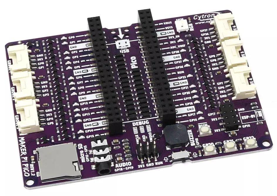 This would be used with a standard Pico or if a display is required with this 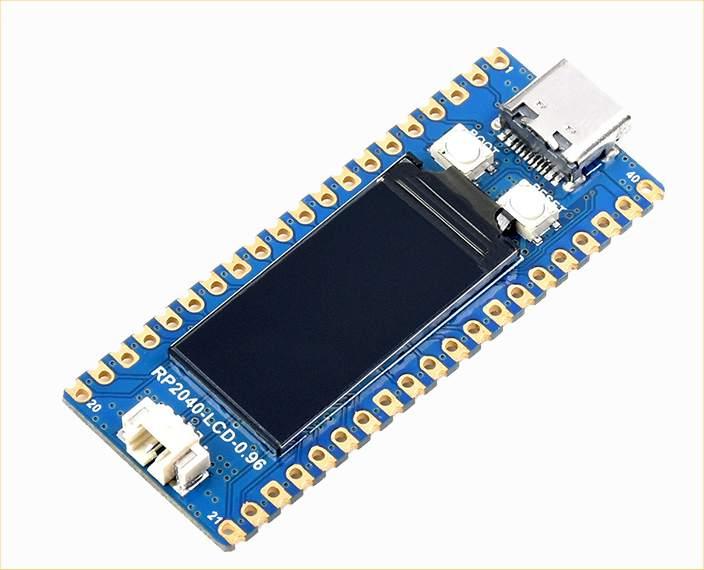 which is a RP2040 with an integrated 0.96inch 160×80 pixels 65K colour IPS LCD display (USD13.99 from Waveshare) We have now already got SDcard, Audio filter and jack, 3 user switches, WS2812 LED, 6 GROVE connectors and LEDs on every pin so all I/O can be monitored. The key is the GROVE connectors. Cables are cheaply available GROVE-GROVE, GROVE-STEMMA, GROVE-QWIC This then open up a huge array of peripherals Grove: Relay, GPS, SSD1306, Buzzer, Accelerometer, ESP8266, Distance, LED Bar, IR, Vibration, etc..... Search for Grove on thepihut.com STEMMA and QWIC Google "ADAFRUIT STEMMA" If necessary the main board could be protected with a polycarbonate sheet top and bottom but at only just over GBP10 for the board and Pico is it even worth it? I can't design anything to compete with the price and variety of the offerings that are now available in this space and, of course, all of them can be supported from MMBasic |
||||
| thwill Guru Joined: 16/09/2019 Location: United KingdomPosts: 4308 |
 ... I think there should be some sort of award for not designing a new PCB ... I think there should be some sort of award for not designing a new PCB  . .Best wishes, Tom MMBasic for Linux, Game*Mite, CMM2 Welcome Tape, Creaky old text adventures |
||||
| Mixtel90 Guru Joined: 05/10/2019 Location: United KingdomPosts: 7889 |
I don't think there's a right or wrong approach - or an approach that's one size fits all for that matter. There's no way young children could cope with a Maker Pi Pico, I don't think. Everything that gets plugged in (if it goes in the right holes and isn't forced in the wrong way round) will be pulled out by its wires. TBH I doubt if many could manage Dupont connectors. And someone *will* cross connect things that shouldn't be cross-connected and break stuff. Yes, it's cheap, but having to replace 20 or so boards per term isn't. And that's not to mention the Picos. There is a reason why school equipment has traditionally been connected using 4mm plugs and sockets. They are virtually indestructible. I have three ex-school "Labpack" power supplies here. They are built like tanks (and are almost as heavy!). They have lasted many years, never mind terms, though but I had to replace the circuit breaker on one. The older kids will be fine with a Maker Pi Pico setup - and may already be into Arduinos at home. They'll know how to work with Duponts and have more manual dexterity and less propensity to shove bits of chewed biscuit into the sockets ... Mick Zilog Inside! nascom.info for Nascom & Gemini Preliminary MMBasic docs & my PCB designs |
||||
| matherp Guru Joined: 11/12/2012 Location: United KingdomPosts: 10273 |
The whole point of this approach is that there are no Dupont and all connectors are keyed and pin matched If you don't think children have the manual dexterity then watch a typical 6 year old with a mobile phone - things have changed since our days |
||||
| Volhout Guru Joined: 05/03/2018 Location: NetherlandsPosts: 5072 |
Huh....what is a mobile phone ?? ;) PicomiteVGA PETSCII ROBOTS |
||||
| The Back Shed's forum code is written, and hosted, in Australia. | © JAQ Software 2025 |
