
|
|
Forum Index : Microcontroller and PC projects : Considerations for a potential "EduMite"
| Author | Message | ||||
| tgerbic Newbie Joined: 25/07/2019 Location: United StatesPosts: 40 |
Looking at the traffic light above brings back memories from 1982. I remember learning the 8080 using one of those little suitcase trainers, including hand coding the program on a machine language coding sheet, and keying in the program on an octal key pad. The first practical thing we learned was the classic traffic light project. I think besides the "making a LED flash" project the traffic light was almost a universal teaching project. I think because the traffic light project requires four sets of traffic indicators and four buttons, the most practical piece of hardware would be all these on a single PCB arranged in a classic road crossing pattern (nothing actually sticking up). The point is not to waste time arranging the physical layout of the system, which should be obvious, but rather concentrate on programming the setup to actually work. Having it on a single board means no web of wiring and stuff slipping all over the desktop. |
||||
| lizby Guru Joined: 17/05/2016 Location: United StatesPosts: 3015 |
Here's a box, 120mm x 80mm x 40mm, which comes with removable end panels. PCBs of the size of those panels with the cutouts for the desired connectors could be produced.  The boxes only cost $3.70 U.S. each with shipping if 4 are bought (I don't know if or at what point shipping costs would begin to rise). You could get both end panels off of a single JLCPCB design, so the end panels for 5 boxes would be about $6.40USD with shipping, giving a total cost of about $5 per box. The top would still need a cutout for an LCD--ILI9341 or ILI9488. With care that could be made with a jig and a side-cutting bit on a drill press. Long pin female headers could stand the LCD off the PCB through the top. 15-pin long pin female header PicoMite, Armmite F4, SensorKits, MMBasic Hardware, Games, etc. on fruitoftheshed |
||||
| phil99 Guru Joined: 11/02/2018 Location: AustraliaPosts: 1781 |
At some stage a cost / benefit analysis to compare bullet proofing versus having a few spare units on hand may be useful. Being able to see the "guts" may be more appealing to some kids than a bland box. |
||||
Quazee137 Guru Joined: 07/08/2016 Location: United StatesPosts: 522 |
I have use similar cases but with clear tops so the LCD can be seen in a very wet environment. Quazee137 |
||||
| Volhout Guru Joined: 05/03/2018 Location: NetherlandsPosts: 3521 |
Maybe we should not Think in small boxes this is educating material. Lunchbox size should be fine. PicomiteVGA PETSCII ROBOTS |
||||
| Quazee137 Guru Joined: 07/08/2016 Location: United StatesPosts: 522 |
May be something like this box they come in many sizes and are low cost. For an after school group. I use one like this for the MM170 back packs and I/O explorer board with a set of parts. The kids liked that they could take it home and play. Used a smaller one for the CMM2 port explorer and parts for another group. |
||||
| Mixtel90 Guru Joined: 05/10/2019 Location: United KingdomPosts: 5725 |
If you are thinking of boxes then I would suggest that you ignore all but Hammond. They have been around a long time, make excellent boxes, have worldwide distribution (not at the whim of a small Chinese company who are buying in unknown stock from another unknown Chinese company) and produce very good drawings for all their boxes. I know there's a cost issue, but if you want a system that's repeatable, possibly over several years and in different countries, then there aren't a lot of options. I wouldn't risk ebay, AliExpress etc. unless you are buying in all you will ever need in one batch. I've been bitten before. The only others that I can think of are the "adaptable boxes" produced by electrical companies as terminal boxes. They are pretty much standardised on sizes now and are used in huge quantities but are generally "industrial ugly" and nowhere near as nice to use as the Hammond cases. Mick Zilog Inside! nascom.info for Nascom & Gemini Preliminary MMBasic docs & my PCB designs |
||||
| matherp Guru Joined: 11/12/2012 Location: United KingdomPosts: 8578 |
Comments above are missing the point on boxes. The box cost is a factor (especially Hammond) but the much cost is machining for cut-outs, installation etc. The number of connectors etc. will not fit on the ends of a standard box so it is the face that must also be machined If this is to work the overall package cost must be sensible. |
||||
| Mixtel90 Guru Joined: 05/10/2019 Location: United KingdomPosts: 5725 |
This page has some 2mm plugs and sockets. In particular, I'd like to point out the low cost sockets that are simply soldered into the PCB. Stackable plugs are here. These could be used in the top PCB of a pair, with the switches etc also directly soldered on. I would have suggested slide switches, but they aren't available in biased configuration. If everything on top went to a down-ward pointing SMD female header then a male header on a bottom PCB could connect the lot without wiring. Perhaps the top PCB could have a rectangular hole covered by plastic and with a SSD1306I2C beneath it? Does that bring enough interactivity by the time a few LEDs have been added? Not at all sure about a potentiometer. Someone will break them against the end stops unless some sort of extra mechanical stops are added by something attatched to the knob. Rotary encoder? Not sure about an SD card either. Not an easily accessible one anyway. I don't think it's needed as teaching stuff can be loaded into flash storage over USB in batches. I know it takes longer than swapping cards, but I don't think you can leave the cards in while the units are in use, particularly if its only a 2 PCB sandwich construction. Edited 2023-03-22 19:31 by Mixtel90 Mick Zilog Inside! nascom.info for Nascom & Gemini Preliminary MMBasic docs & my PCB designs |
||||
| JohnS Guru Joined: 18/11/2011 Location: United KingdomPosts: 3656 |
Tom's ideas (board sandwich / clear plastic sheet(s) leaving sides exposed for connectors) avoid box costs. I guess the downsides are ... what? Kids shoving things in between the layers? SD cards (let alone uSD) will go missing I suspect (or be a choking hazard) plus be another cost, but are they needed anyway? (I think not.) John Edited 2023-03-22 19:46 by JohnS |
||||
| matherp Guru Joined: 11/12/2012 Location: United KingdomPosts: 8578 |
I think we should be guided by Nimue on what should and shouldn't be included - he is the professional. My concern is form-factor and manufacturing to a realistic price |
||||
| Mixtel90 Guru Joined: 05/10/2019 Location: United KingdomPosts: 5725 |
Just some more "morning" ideas. :) I'm coming round to thinking the top should be single-sided PCB (copper on the bottom). Maybe just decorative copper on top. Components mounted through it and soldered in position, as are those 2mm sockets I mentioned. Short leads with 2mm plugs on each end link switches, LEDs etc. to, say, eight GP pins from the PicoMite. This board has a downward-facing female header. Next layer is double-sided PCB. PicoMite is on this layer, now this could be surface mounted as it would be stronger and reduce costs. If it's plugged in then it needs tie-wraps or screws to secure it - it also takes longer to assemble. If a potentiometer or rotary encoder is used it would probably have to be mounted here, with the shaft poking up through a hole. This board has an upward-facing male header and is mechanically connected to the top using threaded 9mm f/f pillars and screws. Bottom layer is just perspex. It is fastened to the middle layer using 5 or 6mm m/f pillars and screws. Four stick-on plastic feet complete it. This design has no side protection, but the 9mm gap could be reduced to 5/6mm if the PicoMite is surface mounted. That might mess with some horizontal connectors though. I suppose an optional layer could be added, holding a battery and charger/protection circuitry. Rather than just connect spare pins to a socket somewhere I'd be happier if we could use as many as possible, only connecting out, say, I2C, 3V3 and GND. Relatively simple expansion modules are then possible without bulky connectors (but needing a bit of software support) - something like the connector used for landline phones would be fine. Mick Zilog Inside! nascom.info for Nascom & Gemini Preliminary MMBasic docs & my PCB designs |
||||
| Mixtel90 Guru Joined: 05/10/2019 Location: United KingdomPosts: 5725 |
Agreed, Peter. In fact, I'd just been back to his PDF - there's nothing like stepping back for a different view. :) I remember that schools used to use a lot of 4mm plugs & sockets. They may well still do so, but to use them effectively for something like this would need a metal box as there are too many possible connections for the weight of a plastic one. Those were the days when we had a load of diecast boxes with components in - way too expensive now unless you have military-grade budgets. Edited 2023-03-22 20:16 by Mixtel90 Mick Zilog Inside! nascom.info for Nascom & Gemini Preliminary MMBasic docs & my PCB designs |
||||
| Volhout Guru Joined: 05/03/2018 Location: NetherlandsPosts: 3521 |
Had only few minutes, so this is my way of looking at it. 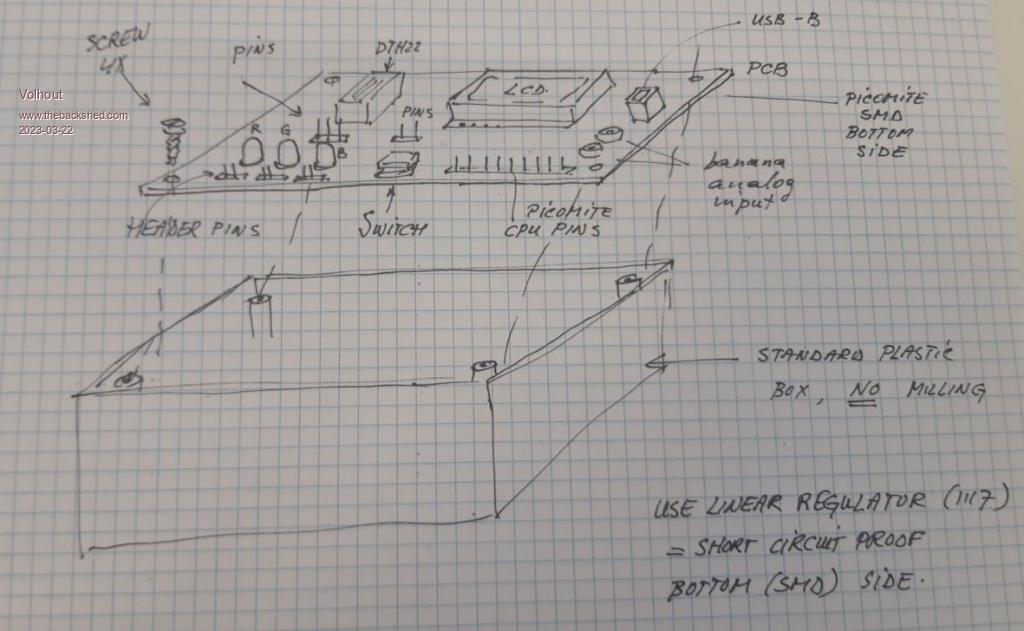 All pins on top side (accessible) are ESD protected with series resistance and diodes. Power is from linear regulator (inherently short circuit protected) banana plugs give access to ADC via resitor network, so you can measure +- 10V LCD is fixed wired to picomite. No access. DTH22 is accessible. LED's and switches are accessible. The PCB acts as lid on the box. No milling, just 4 screws to put together. Linear regulator and picomite are SMD mounted on the bottom, so not accessible. Volhout Edited 2023-03-22 22:55 by Volhout PicomiteVGA PETSCII ROBOTS |
||||
| JohnS Guru Joined: 18/11/2011 Location: United KingdomPosts: 3656 |
I think N is "she" :) But of course er, they, should decide overall. John |
||||
| Mixtel90 Guru Joined: 05/10/2019 Location: United KingdomPosts: 5725 |
There are certainly a lot of ideas here. Unfortunately, last time most of us were in a classroom with a load of 12-year olds we were 12. :) Mick Zilog Inside! nascom.info for Nascom & Gemini Preliminary MMBasic docs & my PCB designs |
||||
| lizby Guru Joined: 17/05/2016 Location: United StatesPosts: 3015 |
I like Volhout's idea, but there's no reason the PCB can't be bigger than the box--say a full 100mm by 100mm. Gives you room to put on an ILI9341 or ILI9488 plus your plug-ins. With an ILI9488 and a PS/2 keyboard, it could be completely free-standing. Regarding polarity, the 37-in-one sensor kit designers solved that for 3-pin modules (with 0V, power, and signal) by putting power in the center. That way, if plugged in wrong, you won't short power to 0V or to the pin--the module just won't work, and can be unplugged and plugged in the right way. Edited 2023-03-23 01:44 by lizby PicoMite, Armmite F4, SensorKits, MMBasic Hardware, Games, etc. on fruitoftheshed |
||||
| Mixtel90 Guru Joined: 05/10/2019 Location: United KingdomPosts: 5725 |
I had a lot of fun laying out a PCB to accept those (PicoMite LEO). :) IIRC there was one I wasn't happy with, but that's because you really need two of them - or something like that. I got all the rest to work using a combination of sockets. The following sockets were used: GP26-5V-GND GND-3V3-GP26-GP27-GP28-GND GP26-GND-5V-GP4-null That board included VGA, PS2 and uSD. And a JDY-40 for fun. :) Edited 2023-03-23 01:20 by Mixtel90 Mick Zilog Inside! nascom.info for Nascom & Gemini Preliminary MMBasic docs & my PCB designs |
||||
| Mixtel90 Guru Joined: 05/10/2019 Location: United KingdomPosts: 5725 |
Right, this is only something to start with. I know it's incomplete, but I wanted to see what it would look like and how awkward the track would be likely to get. I've shown the front and the back of the board. it's shown as 50mm x 100mm but as you can see, space is restricted. This is about as cheap as it's possible to go, single PCB stood on short spacers. The pot is a square trimmer with a built-in knob. The switches are Multicomp from CPC and I left off the power switch, SD card and sensors. Putting stuff on top of a surface mounted PicoMite isn't good so it may have to be plug-in. That's awkward when you don't want to have the pins poking through. 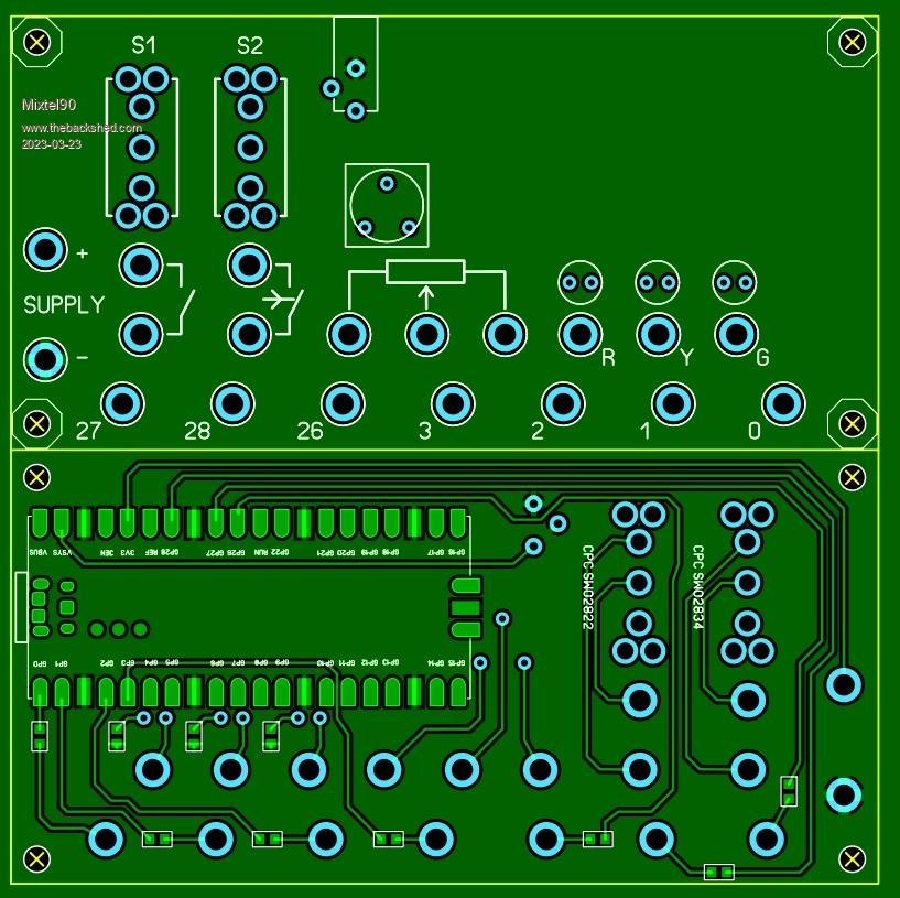 Mick Zilog Inside! nascom.info for Nascom & Gemini Preliminary MMBasic docs & my PCB designs |
||||
| TimD Newbie Joined: 23/02/2021 Location: United KingdomPosts: 27 |
If you do want to include an SD card, you could always have the socket set back from the edge of the PCB a bit, and provide a hole in the PCB for a stubby nut & bolt (Torx if necessary!) just in front of where the SD card will protrude once inserted. This would prevent casual removal of the SD card. Just a thought :-) - Tim |
||||
