
|
|
Forum Index : Microcontroller and PC projects : My PicoMite do not boot
| Page 1 of 2 |
|||||
| Author | Message | ||||
| borg Newbie Joined: 09/12/2020 Location: PolandPosts: 12 |
My PicoMite do not boot. I can connect to terminal by USB when Pi is outside the board, but after inserting it - nothing happens. No VGA, no terminal connection... Am I missing something? Maybe diodes are inserted backwards? Or must I connect something on H1/H2? 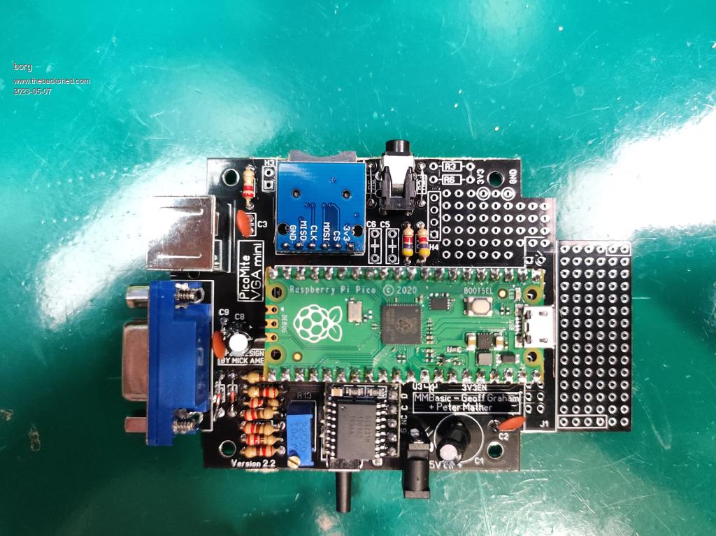 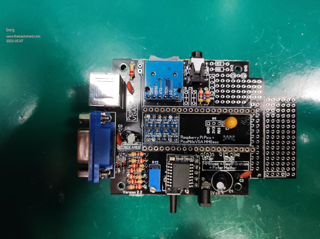 Games and Computers Museum https://gikme.pl/en RetroGaming Chanel https://retrogralnia.yt |
||||
| Mixtel90 Guru Joined: 05/10/2019 Location: United KingdomPosts: 8913 |
I should be able to get you going on this. It's my design. :) Have you got the regulator fitted underneath the board? It's not essential. What test gear have you got? A multimeter should be enough. I can't see from your pictures, but underneath the RTC there should be D1, with the striped end towards the centre of the PCB. Check that pins 36 (3V3) and 39 (VSYS) have been soldered under the board. Edited 2023-05-07 06:08 by Mixtel90 Mick Zilog Inside! nascom.info for Nascom & Gemini Preliminary MMBasic docs & my PCB designs |
||||
| borg Newbie Joined: 09/12/2020 Location: PolandPosts: 12 |
This is a version without regulator. The diod you asked is mounted OK. I have multimeter :) Games and Computers Museum https://gikme.pl/en RetroGaming Chanel https://retrogralnia.yt |
||||
| Mixtel90 Guru Joined: 05/10/2019 Location: United KingdomPosts: 8913 |
Take the Pico and RTC out. Find a GND connection (the + end of D2 & D3 will do, or anywhere else. :) )for the black lead of your meter and check for low resistance or a short from 3V3 to GND. You might get a very short charging pulse from the capacitors but that's all. It should settle down to a high resistance. The regulator is optional. It's surface mount and is fitted underneath the PCB. I can't see anything obvious on the top side of your PCB that would prevent it from booting. Check for solder whiskers between pins, especially between 3V3EN and GND as that would shut down the 3V3 supply. . Edited 2023-05-07 06:30 by Mixtel90 Mick Zilog Inside! nascom.info for Nascom & Gemini Preliminary MMBasic docs & my PCB designs |
||||
| borg Newbie Joined: 09/12/2020 Location: PolandPosts: 12 |
I have short circuit between GND and 3V3... Games and Computers Museum https://gikme.pl/en RetroGaming Chanel https://retrogralnia.yt |
||||
| Mixtel90 Guru Joined: 05/10/2019 Location: United KingdomPosts: 8913 |
Ah, that'll do it. The regulator on the Pico will shut down in that case. On this PCB the top copper surface is connected to 3V3 and the bottom one is connected to GND, if that's of any help. Edited 2023-05-07 06:40 by Mixtel90 Mick Zilog Inside! nascom.info for Nascom & Gemini Preliminary MMBasic docs & my PCB designs |
||||
| borg Newbie Joined: 09/12/2020 Location: PolandPosts: 12 |
F.....ck. The PCBs are defected.... I have short cirrcut on empty pcb... Games and Computers Museum https://gikme.pl/en RetroGaming Chanel https://retrogralnia.yt |
||||
| Mixtel90 Guru Joined: 05/10/2019 Location: United KingdomPosts: 8913 |
Oh! That's unusual. Have a look wherever traces run between others on the Pico connectors. A typical place is by the centre pin of H1, where a 3V3 trace passes next to a GND one. Mick Zilog Inside! nascom.info for Nascom & Gemini Preliminary MMBasic docs & my PCB designs |
||||
| borg Newbie Joined: 09/12/2020 Location: PolandPosts: 12 |
There is connection on pico pin on left side... but its a ground pin. Generally on picco I have connection only on ground and 3v3 out pin. Games and Computers Museum https://gikme.pl/en RetroGaming Chanel https://retrogralnia.yt |
||||
| Mixtel90 Guru Joined: 05/10/2019 Location: United KingdomPosts: 8913 |
Which pin is it? Count anticlockwise from the square one. It wouldn't surprise me if the 8th pin is shorting to 3V3. Edited 2023-05-07 07:21 by Mixtel90 Mick Zilog Inside! nascom.info for Nascom & Gemini Preliminary MMBasic docs & my PCB designs |
||||
| IanRogers Senior Member Joined: 09/12/2022 Location: United KingdomPosts: 152 |
I did post something But never mind.. I didn't read the entire thread.. Going back to sleep now Edited 2023-05-07 15:51 by IanRogers I'd give my left arm to be ambidextrous |
||||
| Mixtel90 Guru Joined: 05/10/2019 Location: United KingdomPosts: 8913 |
Hehe....  It's a bit of a pig trying to find shorts on a bare pcb. :( borg: This is quite an old design for me and I've learned a lot since then :) It's currently up to version 6 and the files for it can be found by following the link in my sig below. PicoMite VGA mini 6. Fits the same box but no longer has a plug-in "sea of holes" board. Mick Zilog Inside! nascom.info for Nascom & Gemini Preliminary MMBasic docs & my PCB designs |
||||
| borg Newbie Joined: 09/12/2020 Location: PolandPosts: 12 |
I will try newer design :) I was starting to think I am missing something obvious... I'm glad I'm not crazy :P Games and Computers Museum https://gikme.pl/en RetroGaming Chanel https://retrogralnia.yt |
||||
| Mixtel90 Guru Joined: 05/10/2019 Location: United KingdomPosts: 8913 |
Where did you get those PCBs made? Mick Zilog Inside! nascom.info for Nascom & Gemini Preliminary MMBasic docs & my PCB designs |
||||
| borg Newbie Joined: 09/12/2020 Location: PolandPosts: 12 |
In PCBway. I'm got more than dozen of projects from them and never have any problem before. Games and Computers Museum https://gikme.pl/en RetroGaming Chanel https://retrogralnia.yt |
||||
| Mixtel90 Guru Joined: 05/10/2019 Location: United KingdomPosts: 8913 |
Interesting. I got mine done at JLCPCB and those came out ok too. Perhaps I didn't allow enough clearence somewhere for PCBway. Did yo manage to haave a look for shorts next to pin 8? It could be on either side of the board as there are parallel tracks there. I think that's the worst place. Mick Zilog Inside! nascom.info for Nascom & Gemini Preliminary MMBasic docs & my PCB designs |
||||
| borg Newbie Joined: 09/12/2020 Location: PolandPosts: 12 |
There are none shorts next to pin 8, except other GND pins... Games and Computers Museum https://gikme.pl/en RetroGaming Chanel https://retrogralnia.yt |
||||
| Mixtel90 Guru Joined: 05/10/2019 Location: United KingdomPosts: 8913 |
The GND pins should only connect to the bottom copper layer, obviously. If you are still having problems and don't want to fit the regulator you can always isolate that suspect bit of track by putting a little drill through the vias at each end to break the internal plating. I don't think you'll be able to find the short with a meter because it's too general (top layer to bottom layer). It'll probably have to be done with a magnifying glass or microscope as the short could be very fine whiskers or just be almost transparent copper if it's a poor etch and buried under the solder resist. There are a few places where a poor etch or a solder whisker could cause a short, but not that many that would short 3V3 to GND. I wish I'd used thinner tracks now, but for some reason I didn't on that one. :( Edited 2023-05-07 23:19 by Mixtel90 Mick Zilog Inside! nascom.info for Nascom & Gemini Preliminary MMBasic docs & my PCB designs |
||||
| al18 Senior Member Joined: 06/07/2019 Location: United StatesPosts: 240 |
The right side of the J1 outline looks unusual. Is that edge scored? Also some of the board edges look rough - it would only take thin copper sliver on the edge to connect the top and bottom sides. I would place sand paper flat on a table and sand the board edges smooth. |
||||
| Mixtel90 Guru Joined: 05/10/2019 Location: United KingdomPosts: 8913 |
That's a very good point. When I cut mine I always give them a bit of a rub with a file to smooth them off a bit. It's a worthwhile step to take. Mick Zilog Inside! nascom.info for Nascom & Gemini Preliminary MMBasic docs & my PCB designs |
||||
| Page 1 of 2 |
|||||
| The Back Shed's forum code is written, and hosted, in Australia. | © JAQ Software 2026 |
