
|
|
Forum Index : Microcontroller and PC projects : PM audio LPF....wow....
| Page 1 of 4 |
|||||
| Author | Message | ||||
Grogster Admin Group Joined: 31/12/2012 Location: New ZealandPosts: 9977 |
I finally got around to trying out the playing of some WAV files via the PM, and I must say, I am extremely impressed with the new LPF design as in the manual, page 31. I believe that Volhort had something to do with the design of this filer? It's really excellent. Playback of a standard 16-bit 44.1kHz WAV file ripped from an audio CD, the sound quality through a decent set of speakers is audibly so good, I can't actually detect any imperfections in the playback. Audiophiles will no doubt find it inferior, but for all intents and purposes of audio playback via the PM, it is astoundingly good - right across the entire frequency range. I have not got to connecting the output to a scope, but I don't think I'll bother! Sounds good enough to me! WHY am I so late to the party on the audio? I spent all my time to date, just designing PCB's and getting code working. Audio or sound effects are the last thing I need to add to the code, but....wow! Impressive. Does the 2040 have some kind of WAV DAC that MMBASIC is tapping into, or is MMBASIC doing all the decoding/streaming in code? EDIT: I tell a lie.  Further experimentation shows that you CAN detect the background PWM noise, but you have to turn up the volume quite a bit, and have some quiet passages in the music. Still, for the purposes of what the PM is, I still think this is excellent audio performance. Further experimentation shows that you CAN detect the background PWM noise, but you have to turn up the volume quite a bit, and have some quiet passages in the music. Still, for the purposes of what the PM is, I still think this is excellent audio performance.Edited 2023-05-31 17:10 by Grogster Smoke makes things work. When the smoke gets out, it stops! |
||||
| Volhout Guru Joined: 05/03/2018 Location: NetherlandsPosts: 5945 |
Hi Grogster, In essence the picomite has dual PWM (left/right audio) running at 44.1kHz (CD sampling frequency) or lower. The WAV file contains DAC values,and these are send to the PWM (after some scaling for i.e. volume). The PWM acts like a DAC, but it has one drawback. The PWM frequency (i.e. 44kHz) is stronger than the audio in it. We are lucky that we cannot hear 44kHz, but audio amplifiers can, so there is a filter that removes the 44kHz. It is a very good solution for CD audio. But ... it will not be perfect in removing other frequencies (i.e. if you play a 16kHz sampled waveform). In that case the MCP4822 DAC that Peter also prototyped is better. Regards, Volhout PicomiteVGA PETSCII ROBOTS |
||||
| Mixtel90 Guru Joined: 05/10/2019 Location: United KingdomPosts: 8913 |
It's all done by the built-in PWM handlers on the RP2040. There's no DAC. Volhout did indeed design the filters. All versions of them since Geoff's original RC filter. :) Getting rid of the 44kHz carrier is non-trivial. Edited 2023-05-31 17:22 by Mixtel90 Mick Zilog Inside! nascom.info for Nascom & Gemini Preliminary MMBasic docs & my PCB designs |
||||
| Hawk Senior Member Joined: 15/07/2021 Location: AustraliaPosts: 155 |
This is good news, as I am also planning to add audio to my Silicon Chip PicoMiteVGA. Has anyone created a shopping list for the components? I'm guessing that the resistors are all 1/4W common resistors, and the capacitors are common ceramic capacitors, but I am unsure about the inductors. Will these ones from Altronics do the job? Altronics 4.7mH inductor 2.7nF also seems to be less available than other values (2.2nF or 3.3nF). Probably means an online order, unless these would do the job. Jaycar 2.7nF Capacitor Hawk Altronics shopping list added. I'm not sure which capacitors are best to use for audio.  Edited 2023-05-31 17:58 by Hawk |
||||
| Volhout Guru Joined: 05/03/2018 Location: NetherlandsPosts: 5945 |
The film capacitors are best, but the ceramics also work fine. I have used both for the 2.7nf. My boards all have film caps for the 33nf and 68nf. Regards, Volhout PicomiteVGA PETSCII ROBOTS |
||||
| Hawk Senior Member Joined: 15/07/2021 Location: AustraliaPosts: 155 |
Thanks for that. Looks like Altronics, which is just down the road from work, don't keep some of the items in stock, so I may have to just bite the bullet and pay for Element 14 or Mouser postage. Is there anything special that should be considered when laying the components on a PCB? Hawk |
||||
| Mixtel90 Guru Joined: 05/10/2019 Location: United KingdomPosts: 8913 |
Don't put the inductors side by side. If you have to do something like that then put other components between them to space them apart. Even better, put them at 90 degrees to each other. You don't want cross-coupling between them and putting them at 90 degrees lets you put them much closer together. Try to get as much of the audio filter away from the PicoMite as you can as any noise picked up will be amplified. If you can, run a clean earth trace from your power input pin to the audio output socket. That prevents heavy noise pulses getting into the audio. Alternatively connect them using a copper pour (ground plane). Disable the on-board switcher by connecting 3V3EN to GND and use a linear 3V3 LDO regulator. This will reduce the noise level a lot. Mick Zilog Inside! nascom.info for Nascom & Gemini Preliminary MMBasic docs & my PCB designs |
||||
| stanleyella Guru Joined: 25/06/2022 Location: United KingdomPosts: 2807 |
I built the non vga circuit but it must have changed to preferred capacitor values. I had to parallel and series the caps I had to get the values. 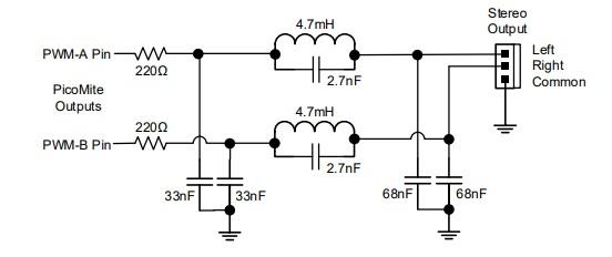 My circuit was then more un-necessarily complicated. 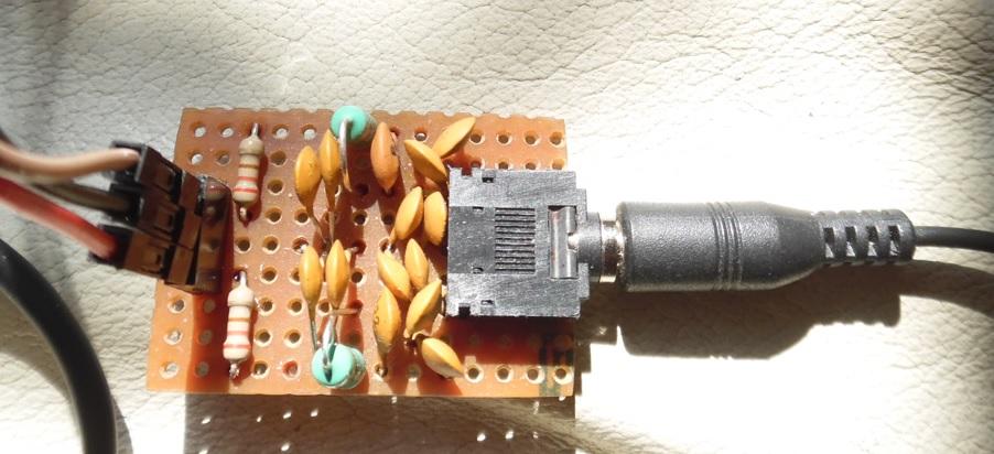 Is this vga manual circuit ok? It's simpler. 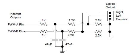 |
||||
| Mixtel90 Guru Joined: 05/10/2019 Location: United KingdomPosts: 8913 |
It will work after a fashion, but the filter isn't as steep and doesn't reduce the 44.1kHz by very much at all. It's nowhere near as good as the inductive version. All three of the correct capacitor values are available from Bitsbox as Polyester film/Mylar capacitors. Postage is always 2.20 UKP. They don't sell the inductors though. Mick Zilog Inside! nascom.info for Nascom & Gemini Preliminary MMBasic docs & my PCB designs |
||||
| stanleyella Guru Joined: 25/06/2022 Location: United KingdomPosts: 2807 |
I had the preferred value caps used but the circuit seems updated since I built it. It works and for me it's for adding sound from the sd card , for a robot maybe. Playing with tone is fun, I added 2 tones to tron game which makes it interesting. I got the inductors from ebay 2 for £2 odd free p&p. I haven't got a good explosion/crash sound yet. I haven't tried flac yet but vlc player can convert wav to flac. |
||||
| LucV Regular Member Joined: 19/02/2023 Location: NetherlandsPosts: 62 |
I am still using the old version of the filter (the one from the VGA manual stanlyella posted) and I was blown away when I first heard it. So I made a small fun project. I downloaded an audio file that plays a blackbird singing. Put it on an SD card. The Pico is equipped with an SD-card adapter and a PIR and the audio setup.. Everytime someone walks by the bird starts to sing........ There is actually a commercial product that does this, it is called the Zwitscherbox and sold for about 40-50 Euro. Well my Pico of 4 Euro. a PIR of 3 euro and some resistors and capacitors do the same now...... Oh, and no !! You may not use this idea for the upcoming contest.........  Edited 2023-06-01 04:51 by LucV Luc's tech Blog |
||||
| Volhout Guru Joined: 05/03/2018 Location: NetherlandsPosts: 5945 |
vogeltje For the dutch people Volhout Edited 2023-06-01 05:08 by Volhout PicomiteVGA PETSCII ROBOTS |
||||
| stanleyella Guru Joined: 25/06/2022 Location: United KingdomPosts: 2807 |
If this is the old version where is the latest version/circuit please? |
||||
| stanleyella Guru Joined: 25/06/2022 Location: United KingdomPosts: 2807 |
daft idea but can't a wave at the same frequency but opposite phase or in this case inverted be used to cancel the carrier and just leave the audio? |
||||
| Hawk Senior Member Joined: 15/07/2021 Location: AustraliaPosts: 155 |
Others with more hardware experience than me will probably chime in, but my understanding is that the 44kHz is generated internally in the Pico. To cancel it out using that method, you would need access to it and ensure that the inverted signal that you are going to add to the generated signal is in phase with the original signal. May take a lot more electronics and active components that then potentially introduce more noise. Hawk |
||||
| Grogster Admin Group Joined: 31/12/2012 Location: New ZealandPosts: 9977 |
I remember reading in a post from Peter, that the 4mH7 inductor does have to have certain characteristics, so perhaps be careful with that. I used these ones here, and they have some in stock. I seem to recall it was the ESR of 20-ohms that was the important bit - going from my memory. Really cheap inductors on eBay might produce sub-standard results. Volhout would probably be able to tell us all what the effect on the filter will be, with inductors of different ESR's.... Smoke makes things work. When the smoke gets out, it stops! |
||||
| Volhout Guru Joined: 05/03/2018 Location: NetherlandsPosts: 5945 |
Hi Grogster, The inductors you specify are fine. In general you will find leaded inductors in the range of 10-30 ohms internal resistance. These ones are 20 ohms. Regards, Volhout note: In the earliest discussions on the filter I designed with different values. With these different values the filter was more critical on parameters, and it would require certain manufacturer/type number with narrow tolerance. Not anymore. The final 4.7mH filter is easier on tolerances. PicomiteVGA PETSCII ROBOTS |
||||
| Volhout Guru Joined: 05/03/2018 Location: NetherlandsPosts: 5945 |
The audio output is PWM when using the filter, and DAC when using the MCP4822 DAC. To remove the 44kHz from the PWM signal the simplest option is a filter. More advanced methods can be implemented, but these required significantly more electronics. Alternatively you can use an electronic FIR filter (chip) but that requires you to provide a clock signal. The inductor filter is simply the simplest solution, not requiring any extra IO pins, is relatively cheap and forgiving. The filter in the older VGA user manual (and on the earlier VGA picomite designs) is not performing as well, but may be adequate for some applications. A lot has been said about audio in the picomite threads, it is an continuous discussion item since most forum members have - different parts in their junk box - different applications What I advise to all that want to design their own filter: borrow/rent/take and oscilloscope and measure .... very educative ... Look at the picomite IO pin, and look at the audio signal from (any) filter. A simple PLAY TONE command will help you. Then set PLAY VOLUME to 0. The remaining signal you see on the scope should be close to nothing.... Volhout Volhout PicomiteVGA PETSCII ROBOTS |
||||
| stanleyella Guru Joined: 25/06/2022 Location: United KingdomPosts: 2807 |
I tried 2 tones on usb hantek. Sine wave were bit "jittery" and not trigger ie keep moving.. but the scope has x y mode, which I've never tried. I'll try in a while and post if successful. Should get a circle at same freq and then Lissajous with different freqs. I heard good things about using a scope with x y mode as a component tester. I'll let you know. It's just an experiment. stan. |
||||
| Mixtel90 Guru Joined: 05/10/2019 Location: United KingdomPosts: 8913 |
Sync on the little Hantek isn't brilliant, but some of that jitter is caused by the 44.1kHz carrier that the sine wave is riding on. The scope is trying to sync to both the sine wave and the carrier - and it fails, of course. Lissajous figures depend on the phase difference between the X and Y inputs. You don't get a circle with the same frequency on both unless they are exactly 90 degrees out of phase. All clever stuff! A trick you can rarely do now (not with any DSOs AFAIK) is spot wheel patterns, where you form a circle using a sine wave and 90 degree phase shift on the X and Y inputs then send blanking pulses to the grid of the tube. You see a ring of dots or dashes, the number of which depends on the frequency relationship between the sine wave and the blanking pulses. They also rotate if the frequency isn't exactly divisible. Mick Zilog Inside! nascom.info for Nascom & Gemini Preliminary MMBasic docs & my PCB designs |
||||
| Page 1 of 4 |
|||||
| The Back Shed's forum code is written, and hosted, in Australia. | © JAQ Software 2026 |
