
|
|
Forum Index : Microcontroller and PC projects : Armmite F4 LCD interface PCB
| Page 1 of 3 |
|||||
| Author | Message | ||||
| Mixtel90 Guru Joined: 05/10/2019 Location: United KingdomPosts: 8913 |
As mentioned in another thread, I've been sorting out a "backpack" that allows a Armmite F4 to be mounted behind a SSD1963 without losing access to the IO pins. The prototype boards have just arrived! 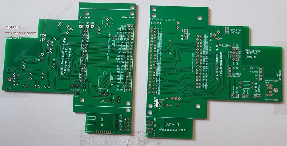 Just some connectors to arrive then it'll be playtime. :) The JDY-40 is an adapter board that is cut off. Also, two lines indicate where to cut the board to fit it behind a 4.3 inch display. I have some ides for a version 2, but nothing in the pipeline yet. . Edited 2023-09-13 18:38 by Mixtel90 Mick Zilog Inside! nascom.info for Nascom & Gemini Preliminary MMBasic docs & my PCB designs |
||||
| Mixtel90 Guru Joined: 05/10/2019 Location: United KingdomPosts: 8913 |
Dry assembly run so you can see the general idea: 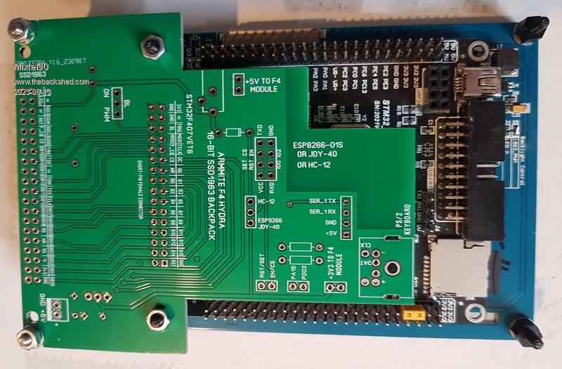 It's intended to have two short pieces of PCB material from the RH corners of the F4 to the two little pillars on the rear of the display. That stiffens the assembly to prevent any risk of contact between the rears of F4 and display. It's designed to be mounted behind a front panel so there are 5mm spacers on the front of the display PCB. The total depth of the assembly from the rear of a front panel to the rear of a back stud is approximately 32mm, so it's pretty compact. . Edited 2023-09-13 20:07 by Mixtel90 Mick Zilog Inside! nascom.info for Nascom & Gemini Preliminary MMBasic docs & my PCB designs |
||||
| Mixtel90 Guru Joined: 05/10/2019 Location: United KingdomPosts: 8913 |
I got my LCD connectors today and panicked a bit when the system didn't work first time. It helps if you remember to connect the backlight to the PWM output, doesn't it? :) I've not fully equipped it yet, but so far there have been no problems. There are changes that could do to be made really, but nothing serious. As I said previously, I'll have four of these for sale as kits. I just need to sort out the bits and a price. It won't be much, I mainly want to clear the cost of the boards, and long-tail connectors. The kit will include a PCB, all mounting pillars, screws, nuts & washers, F4 connector and SSD1963 connector. I'll try to knock up some sort of instruction sheet too as it's not blindingly obvious what can be done with it. Incidentally, my 5" display seems to be fine when powered from the USB input to the Armmite F4. I'm just relieved that I've finally got this display to work. :) It hadn't run until today and I've had it more or less since I got the F4 ages ago. Mick Zilog Inside! nascom.info for Nascom & Gemini Preliminary MMBasic docs & my PCB designs |
||||
| TrevorH Senior Member Joined: 06/04/2018 Location: United KingdomPosts: 145 |
Hi Mick, Can I put my name on one of these boards for when you have priced them up?? Trevor. |
||||
| Mixtel90 Guru Joined: 05/10/2019 Location: United KingdomPosts: 8913 |
Certainly, no problem. I'm just writing the instructions. Mick Zilog Inside! nascom.info for Nascom & Gemini Preliminary MMBasic docs & my PCB designs |
||||
| pwillard Guru Joined: 07/06/2022 Location: United StatesPosts: 341 |
Wow, nice work |
||||
| Mixtel90 Guru Joined: 05/10/2019 Location: United KingdomPosts: 8913 |
Instruction book. Armmite F4 Hydra Instructions.pdf Now to sort out prices. :) Mick Zilog Inside! nascom.info for Nascom & Gemini Preliminary MMBasic docs & my PCB designs |
||||
| matherp Guru Joined: 11/12/2012 Location: United KingdomPosts: 11543 |
It would be good if you could also support the 4" 800x480 displays (like this) . These are now more economical than the SSD and fully supported on the ArmmiteF4 |
||||
| Mixtel90 Guru Joined: 05/10/2019 Location: United KingdomPosts: 8913 |
It's difficult to tell from the pics on that site, but I think the pinout is a bit too different to do it on the same board. I'll have a look though - if I can find a clear enough pic. ...... spoke too soon, found one. :) It has to be a different board. 2x17 connector and the control pins are all over the place. I'll have a look at it. Edited 2023-09-17 01:36 by Mixtel90 Mick Zilog Inside! nascom.info for Nascom & Gemini Preliminary MMBasic docs & my PCB designs |
||||
| lizby Guru Joined: 17/05/2016 Location: United StatesPosts: 3788 |
Fwiw, here's an F4 adapter for that 800x480 issue display-- near the end of the thread. IPS LCD Edited 2023-09-17 03:22 by lizby PicoMite, Armmite F4, SensorKits, MMBasic Hardware, Games, etc. on FOTS |
||||
| Mixtel90 Guru Joined: 05/10/2019 Location: United KingdomPosts: 8913 |
I'm almost there with a version for that display. It is designed to work with both variations of the Armmite F4. Includes beep/click, Comm module socket, PS/2, audio jack, 3V3 reg for the F4 as these displays appear to be 5V only. Unfortunately I can't test this one. :( Mick Zilog Inside! nascom.info for Nascom & Gemini Preliminary MMBasic docs & my PCB designs |
||||
| lizby Guru Joined: 17/05/2016 Location: United StatesPosts: 3788 |
I'll be happy to test when gerbers are available & JLC order has arrived. PicoMite, Armmite F4, SensorKits, MMBasic Hardware, Games, etc. on FOTS |
||||
| Mixtel90 Guru Joined: 05/10/2019 Location: United KingdomPosts: 8913 |
This is the version for the 4" 800x480 display: The Hydra 40-80 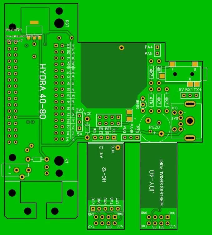 Gerbers: Hydra 40-80.zip No instructions yet, I've not got around to it. :) This one is a more complex shape than usual and is a 4-layer board so it will very likely cost a little more to get it made. Edited 2023-09-17 22:38 by Mixtel90 Mick Zilog Inside! nascom.info for Nascom & Gemini Preliminary MMBasic docs & my PCB designs |
||||
| lizby Guru Joined: 17/05/2016 Location: United StatesPosts: 3788 |
$8.98USD for 5 shipped to Nova Scotia. Thanks. Does this look right?  PicoMite, Armmite F4, SensorKits, MMBasic Hardware, Games, etc. on FOTS |
||||
| Mixtel90 Guru Joined: 05/10/2019 Location: United KingdomPosts: 8913 |
As far as I can tell it's ok. :) You need x-ray vision to see the two inner layers. The little L-shaped pieces support the loose end of the Armmite on 5mm pillars on the back of the display. The two long, narrow boards are optional COMM modules. All these need to be cut off, but I've allowed a little leeway so that they could be cut with a fine saw or probably even a junior hacksaw without encroaching on anything important. The "proper" assembly is intended to be dome like the Hydra board, except that the L-shaped pieces are supplied. If you power from the USB connection: Fit a wire link from the serial port 5V pin to the Hydra 5V pin. Ideally you shouldn't fit the regulator - I forgot to fit a link here. What will happen is that the outputs of the Armmite regulator and the Hydra regulator will be in parallel. That shouldn't cause a problem as the load is nowhere near the full load of a single regulator so current scaring isn't an issue. If you haven't actually placed the order yet I'm quite willing to include a link and re-do the gerbers. If you want to power from the external 5V connection: You will need the regulator as it powers the Armmite at 3V3. Note that you always need 5V to the board from somewhere if you want the PS/2 keyboard. Mick Zilog Inside! nascom.info for Nascom & Gemini Preliminary MMBasic docs & my PCB designs |
||||
| Mixtel90 Guru Joined: 05/10/2019 Location: United KingdomPosts: 8913 |
I've made a couple of slight changes so here are some new gerbers, if I'm not too late. 1: There is now a removable link to disconnect the 3V3 feed to the Armmite. 2: I've added a Schottky diode to prevent powering the Armmite from the Hydra 5V line. This will protect the USB input but will lose a bit of voltage to the display. If that's a problem it can be linked out. The Armmite can now be powered from either USB or at 3V3 via the Hydra regulator. 3: I've corrected the Pin 1 position indication on the display and Armmite connectors. None of these are deal breakers, but nice to get sorted early. Hydra 40-80.zip . Mick Zilog Inside! nascom.info for Nascom & Gemini Preliminary MMBasic docs & my PCB designs |
||||
| Mixtel90 Guru Joined: 05/10/2019 Location: United KingdomPosts: 8913 |
After that brief interlude, back to the prototype SSD1963 board kits that are for sale. :) The cost of a kit is 3.80 UKP + postage. Remember, these are complete kits but you will still have to do a little messing about with mechanical mounting to fix them to the display properly. Postage within the UK is 90p (first class letter) so 4.70 UKP in total. International postage (to the US or Netherlands anyway, probably many other places) is 2.20 UKP (standard letter post) so 6.00 UKP in total. I would appreciate payment via Paypal transfer if possible. Please PM me if you are interested. One already reserved for Trevor. There are currently three kits still available. Mick Zilog Inside! nascom.info for Nascom & Gemini Preliminary MMBasic docs & my PCB designs |
||||
| JohnS Guru Joined: 18/11/2011 Location: United KingdomPosts: 4336 |
I believe with regret that 1st class is now £1.10. John |
||||
| Mixtel90 Guru Joined: 05/10/2019 Location: United KingdomPosts: 8913 |
Drat... Curses upon non-updating web pages! Oh well, Sorry 'bout that, folks, but the cost of the bits is the cost of the bits. As compensation I'm now including the two M2.5 screws & nuts for the free end of the Armmite F4. I used M2.5 here to allow a bit of leeway in the fixings. . Edited 2023-09-19 18:19 by Mixtel90 Mick Zilog Inside! nascom.info for Nascom & Gemini Preliminary MMBasic docs & my PCB designs |
||||
| okwatts Regular Member Joined: 27/09/2022 Location: CanadaPosts: 67 |
I ordered the Hydra40-80 (revised version), now in production at JLCPCB. Will ship on the slow option so I'm looking forward to any updates @lizby on your findings. Also interested to know if any instructions are being contemplated that are different from those for the SSD1963 that are given regarding options. I appreciate that @mixtel90 doesn't have the display (and time?) so construction hints and options to configure will be done by inference and comparison using the schematics. Thanks for your continued support of all things MMBasic related. |
||||
| Page 1 of 3 |
|||||
| The Back Shed's forum code is written, and hosted, in Australia. | © JAQ Software 2026 |
