
|
|
Forum Index : Microcontroller and PC projects : Armmite F4: PCB adaptor for IPS/OTM8009A 800*480 LCD
| Author | Message | ||||
| lizby Guru Joined: 17/05/2016 Location: United StatesPosts: 3784 |
This adaptor enables you to use the 16-bit IPS/OTM8009A LCD with the F4--converting the 32 pins to the 34-pin IPS. One anomaly I noticed--if I power-cycled after OPTION LCDPANEL IPS_4_16,L without doing OPTION TOUCH, the LCDPANEL setting reverted to the default. After OPTION TOUCH PB12, PC5 all was fine. The image is very crisp--this photo doesn't do it justice (aside from the fact that the screen is highly reflective and in the camera, catches what is facing it--though not so noticeable when not taking a picture). 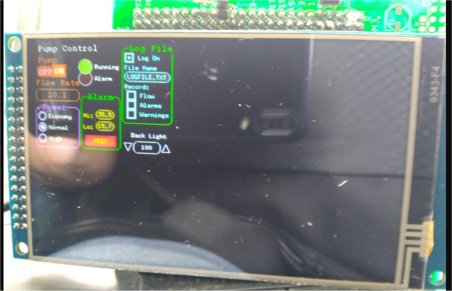 Another anomaly: SAVE IMAGE did a very poor job of rendering the screen, especially compared to the SSD1963 and other displays. 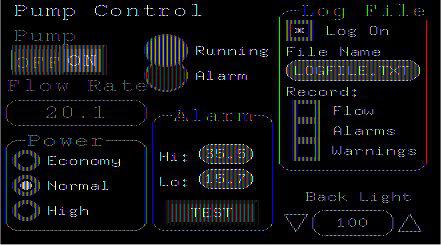 The adaptor works with the F4 hat PCB recently published, and so also with the 2x20 expansion port PCB. Attached are the zipped gerber files which can be sent directly to JLCPCB, and the EagleCad .sch and .brd files. F4_800_LCD_2021-02-22.zip F4_800_LCD.zip PicoMite, Armmite F4, SensorKits, MMBasic Hardware, Games, etc. on FOTS |
||||
disco4now Guru Joined: 18/12/2014 Location: AustraliaPosts: 1127 |
Hi Lizby, It looks like the colours are not being mapped properly when doing the save image. I will see what it does for me.Its saving enough pixels, just not the correct colours. Do you have the pump controller demo converted to run 480 * 320. If so can I have a copy to reference for the manual. Regards Gerry F4 H7FotSF4xGT |
||||
| lizby Guru Joined: 17/05/2016 Location: United StatesPosts: 3784 |
Hi, Gerry, The pump controller demo is just the 320x240 version. I can try converting it to 480x320 if you like. PicoMite, Armmite F4, SensorKits, MMBasic Hardware, Games, etc. on FOTS |
||||
| lizby Guru Joined: 17/05/2016 Location: United StatesPosts: 3784 |
Here's the 480x320 version. I basically increased all the X,Ys and the widths and heights by 50%, and changed font 1 to font 4 and font 2 to font 5. And then fiddled to adjust. 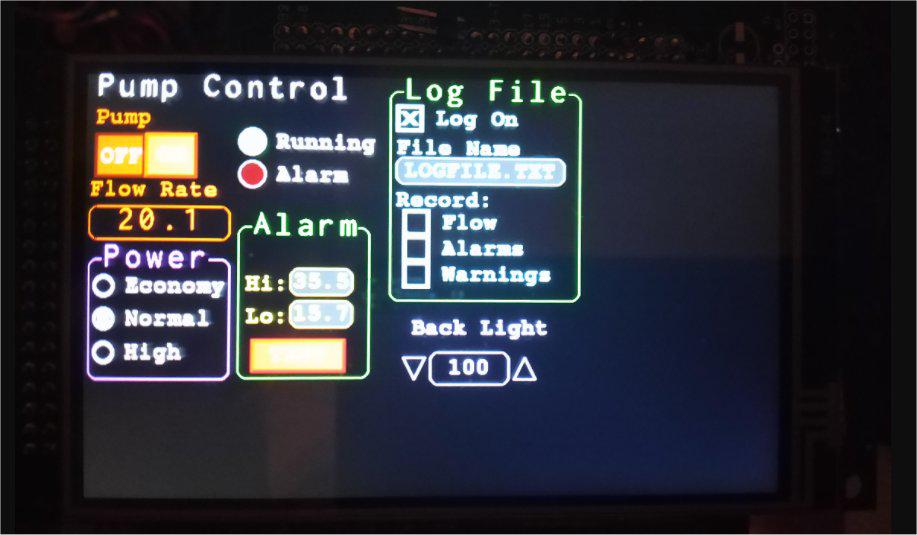 ''''''''''''''''''''''''''''''''''''''''''''''''''''''''''''''''' ' Demonstration program for the Micromite+ ' It does not do anything useful except demo the various controls ' ' Geoff Graham, October 2015 ' Modified to 480x320 by Lance Benson (lizby) April 2021 ''''''''''''''''''''''''''''''''''''''''''''''''''''''''''''''''' Option Autorun On Option Explicit ' gui calibrate Dim ledsY Colour RGB(white), RGB(black) ' reference numbers for the controls are defined as constants Const c_head = 1, c_pmp = 2, sw_pmp = 3, c_flow = 4, tb_flow = 5 Const led_run = 6, led_alarm = 7 Const frm_alarm = 20, nbr_hi = 21, nbr_lo = 22, pb_test =23 Const c_hi = 24, c_lo = 25 Const frm_pump = 30, r_econ = 31, r_norm = 32, r_hi = 33 Const frm_log = 40, cb_enabled = 41, c_fname = 42, tb_fname = 43 Const c_log = 44, cb_flow = 45, cb_pwr = 46, cb_warn = 47 Const cb_alarm = 48, c_bright = 49, sb_bright = 50 ' now draw the "Pump Control" display CLS dim integer f1=4,f2=5 ' LB GUI Interrupt TouchDown, TouchUp ' display the heading Font f2 : GUI Caption c_head, "Pump Control", 10, 0 Font f1 : GUI Caption c_pmp, "Pump", 10, 37, , RGB(brown) ' now, define and display the controls ' first display the switch Font f1 GUI Switch sw_pmp, "OFF|ON", 10, 67, 115, 50, RGB(white),RGB(brown) CtrlVal(sw_pmp) = 1 ' the flow rate display box Font f1 : GUI Caption c_flow, "Flow Rate", 5, 119,, RGB(brown),0 Font f2 : GUI Displaybox tb_flow, 5, 150, 157, 37 CtrlVal(tb_flow) = "20.1" ' the radio buttons and their frame Font f2 : GUI Frame frm_pump, "Power", 5, 210, 157, 135,RGB(200,20,255) Font f1 GUI Radio r_econ, "Economy", 22, 240, 12, RGB(230, 230, 255) GUI Radio r_norm, "Normal", 22, 277 GUI Radio r_hi, "High", 22, 315 CtrlVal(r_norm) = 1 ' start with the "normal" button selected ' the alarm frame with two number boxes and a push button switch Font f2 : GUI Frame frm_alarm, "Alarm", 172, 172, 147, 172,RGB(green) Font f1 GUI Caption c_hi, "Hi:", 180, 225, LT, RGB(yellow) GUI Numberbox nbr_hi, 230,MM.VPos-6,70,MM.FontHeight+6,RGB(yellow),RGB(64,64,64) GUI Caption c_lo, "Lo:", 180, 262, LT, RGB(yellow),0 GUI Numberbox nbr_lo, 230,MM.VPos-6,70,MM.FontHeight+6,RGB(yellow),RGB(64,64,64) GUI Button pb_test, "TEST", 187, 300, 105, 37,RGB(yellow), RGB(red) CtrlVal(nbr_lo) = 15.7 : CtrlVal(nbr_hi) = 35.5 ' draw the two LEDs Const ledsX = 187, coff = 75 ' define their position ledsY = 75 : GUI LED led_run, "Running", ledsX, ledsY, 15, RGB(green) ledsY = ledsY+37 : GUI LED led_alarm, "Alarm", ledsX, ledsY, 15, RGB(red) CtrlVal(led_run) = 1 ' the switch defaults to on so set the LED on ' the logging frame with check boxes and a text box Colour RGB(cyan), 0 Font f2 'GUI Frame frm_log, "Log File", 210, 10, 110, 160, RGB(green),0 GUI Frame frm_log, "Log File", 343, 15, 220, 240, RGB(green) Font f1 GUI Checkbox cb_enabled, "Log On", 350, 30, 30, RGB(cyan) GUI Caption c_fname, "File Name", 350, 67 GUI Textbox tb_fname, 350, 90, 195, 30, RGB(cyan), RGB(64,64,64) GUI Caption c_log, "Record:", 350, 127, , RGB(cyan), 0 GUI Checkbox cb_flow, "Flow", 358, 150, 30 GUI Checkbox cb_alarm, "Alarms", 358, 180, 30 GUI Checkbox cb_warn, "Warnings", 358, 210, 30 CtrlVal(cb_enabled) = 1 CtrlVal(tb_fname) = "LOGFILE.TXT" ' define and display the spinbox for controlling the backlight GUI Caption c_bright, "Back Light", 368, 275,,RGB(200,200,255),0 GUI Spinbox sb_bright, 353, 315, 165, 37,,,10, 10, 100 CtrlVal(sb_bright) = 100 ' All the controls have been defined and displayed. At this point ' the program could do some real work but because this is just a ' demo there is nothing to do. So it just sits in a loop. Do : Loop ' the interrupt routine for touch down ' using a select case command it has a different process for each ' control Sub TouchDown Select Case Touch(REF) ' find out the control touched Case cb_enabled ' the enable check box If CtrlVal(cb_enabled) Then GUI Restore c_fname, tb_fname, c_log, cb_flow, cb_alarm, cb_warn Else GUI Disable c_fname, tb_fname, c_log, cb_flow, cb_alarm, cb_warn EndIf Case sb_bright ' the brightness spin box BackLight CtrlVal(sb_bright) Case sw_pmp ' the pump on/off switch Print CtrlVal(sw_pmp) CtrlVal(led_run) = CtrlVal(sw_pmp) CtrlVal(tb_flow) = Str$(CtrlVal(sw_pmp) * 20.1) CtrlVal(r_norm) = 1 Case pb_test ' the alarm test button Open "Test.txt" For Append As #1 Print "File Opened" Print #1, "Hello World", Time$ Print "Hello World", Time$ Close #1 Print "File Closed" CtrlVal(led_alarm) = 1 GUI beep 250 Case r_econ ' the economy radio button CtrlVal(tb_flow) = Str$(CtrlVal(sw_pmp) * 18.3) Case r_norm ' the normal radio button CtrlVal(tb_flow) = Str$(CtrlVal(sw_pmp) * 20.1) Case r_hi ' the high radio button CtrlVal(tb_flow) = Str$(CtrlVal(sw_pmp) * 23.7) End Select End Sub ' interrupt routine when the touch is removed Sub TouchUp Select Case Touch(LASTREF) ' use the last reference Case pb_test ' was it the test button CtrlVal(led_alarm) = 0 ' turn off the LED End Select End Sub PicoMite, Armmite F4, SensorKits, MMBasic Hardware, Games, etc. on FOTS |
||||
| disco4now Guru Joined: 18/12/2014 Location: AustraliaPosts: 1127 |
Hi Lance, Try this LCD Integrity test program and see what the results are. One of my OTM8009As passes every time, one does get a couple of pixels wrong about half the time, so something may be marginal, I think on the reading side. Are you running the display on 3.3v (I am) and is it just from USB power or a good 5v source. Regards Gerry Edited 2021-04-14 18:12 by disco4now F4 H7FotSF4xGT |
||||
| lizby Guru Joined: 17/05/2016 Location: United StatesPosts: 3784 |
Gerry--I need the "REFERENCE.BMP" file to complete the test. Interestingly, the right-hand flicker I am seeing at times appears in the test only at backlight levels 70 and above. Attached is zipped test.bmp from the run. test.zip (The 480x320 guidemo program above shows no right-hand shadow flickering when BACKLIGHT 50 is added at the beginning.) I'm running off of USB on a laptop. I have it plugged into an in-line current monitoring module. That shows 240mA when the backlight wasn't set, 140mA when it is (with my F4 hat PCB also plugged into the F4, but with nothing connected to it.. ~ Edited 2021-04-14 23:18 by lizby PicoMite, Armmite F4, SensorKits, MMBasic Hardware, Games, etc. on FOTS |
||||
| disco4now Guru Joined: 18/12/2014 Location: AustraliaPosts: 1127 |
The REFERENCE.BMP is created by the first successful test, its just a copy of test.bmp Try running with the ILI9341_16 first, it should pass the test and created the file. Here is one that should be ok REFERENCE.zip Edited 2021-04-14 23:22 by disco4now F4 H7FotSF4xGT |
||||
| lizby Guru Joined: 17/05/2016 Location: United StatesPosts: 3784 |
Thanks for that file. Here's the output--lots of "FAILED" tests but in practice, thus far, I'm not seeing any problems other than with SAVE IMAGE (after adjusting the backlight fixed the shadow flickering). > load "verify_ips.bas" > RUN LCDPANEL Integrity Test Armmite F4 ---------------------------------- Short Test - 100*100 pixels tested IPS_4_16 0 TEST RGB colour order ************************************************** BACKLIGHT TEST 10-100% ************************************************** ************************************************** TRANSPARENT TEXT TEST ************************************************** ************************************ Doing write to Pixels colour gradiant and then read of pixels. ************************************ writing 10000 pixels... 1713 mSec reading 10000 pixels... Pixels not read as written 000000000000010000001000 @ 0 1 000000000000000000001000 000000000000110000011000 @ 0 3 000000000000100000011000 000000000001010000101000 @ 0 5 100000000001010000101000 000000000001110000111000 @ 0 7 100000000001110000111000 000000000010010001001000 @ 0 9 000000000010000001001000 000000000010110001011000 @ 0 11 000000000010100001011000 000000000011010001101000 @ 0 13 100000000011010001101000 000000000011110001111000 @ 0 15 100000000011110001111000 000000000100000010000000 @ 0 16 000000000100000000000000 000000000100010010001000 @ 0 17 000000000100000000001000 000000000100100010010000 @ 0 18 000000000100100000010000 000000000100110010011000 @ 0 19 000000000100100000011000 000000000101000010100000 @ 0 20 000000000101000000100000 000000000101010010101000 @ 0 21 100000000101010000101000 000000000101100010110000 @ 0 22 000000000101100000110000 000000000101110010111000 @ 0 23 100000000101110000111000 000000000110000011000000 @ 0 24 000000000110000001000000 000000000110010011001000 @ 0 25 000000000110000001001000 000000000110100011010000 @ 0 26 000000000110100001010000 000000000110110011011000 @ 0 27 000000000110100001011000 2767 mSec correct pixels 1928 incorrect pixels 8072 total pixels 10000 ************************************ Doing BLIT - blit 0,0,0,0,100,100 and re read of pixels. ************************************ reading 10000 pixels after blit ... Pixels not read as written 000000000000010000001000 @ 0 1 001000000000000000100000 000000000000100000010000 @ 0 2 011010000011100000001000 000000000000110000011000 @ 0 3 000100000000000000111000 000000000001000000100000 @ 0 4 000000000000100000011000 000000000001010000101000 @ 0 5 001110000000000000100000 000000000001100000110000 @ 0 6 111010000100010000100000 000000000001110000111000 @ 0 7 001010000000000000111000 000000000010000001000000 @ 0 8 000000000001100000110000 000000000010010001001000 @ 0 9 001100000000000000100000 000000000010100001010000 @ 0 10 011010000101000000111000 000000000010110001011000 @ 0 11 010000000000000000111000 000000000011000001100000 @ 0 12 000000000010000001001000 000000000011010001101000 @ 0 13 011010000000000000100000 000000000011100001110000 @ 0 14 011010000101100001010000 000000000011110001111000 @ 0 15 010110000000000000111000 000000000100000010000000 @ 0 16 000000000011000001100000 000000000100010010001000 @ 0 17 011000000000000000100000 000000000100100010010000 @ 0 18 011010000110100001101000 000000000100110010011000 @ 0 19 011100000000000000111000 000000000101000010100000 @ 0 20 100000000011110001111000 2821 mSec correct pixels 2 incorrect pixels 9998 total pixels 10000 ************************************ Doing SAVE IMAGE TEST.BMP ,0,0,100,100 then RESTORE IMAGE TEST.BMP 0,0 and re read of pixels. ************************************ Image saved as TEST.BMP Loading Image TEST.BMP reading 10000 pixels after LOAD IMAGE ... Pixels not read as written 000000000000010000001000 @ 0 1 001000000000000000100000 000000000000100000010000 @ 0 2 011010000011100000001000 000000000000110000011000 @ 0 3 000100000000000000111000 000000000001000000100000 @ 0 4 000000000000100000011000 000000000001010000101000 @ 0 5 001110000000000000100000 000000000001100000110000 @ 0 6 111010000100010000100000 000000000001110000111000 @ 0 7 001010000000000000111000 000000000010000001000000 @ 0 8 000000000001100000110000 000000000010010001001000 @ 0 9 001100000000000000100000 000000000010100001010000 @ 0 10 011010000101000000111000 000000000010110001011000 @ 0 11 010000000000000000111000 000000000011000001100000 @ 0 12 000000000010000001001000 000000000011010001101000 @ 0 13 011010000000000000100000 000000000011100001110000 @ 0 14 011010000101100001010000 000000000011110001111000 @ 0 15 010110000000000000111000 000000000100000010000000 @ 0 16 000000000011000001100000 000000000100010010001000 @ 0 17 011000000000000000100000 000000000100100010010000 @ 0 18 011010000110100001101000 000000000100110010011000 @ 0 19 011100000000000000111000 000000000101000010100000 @ 0 20 100000000011110001111000 2839 mSec correct pixels 1 incorrect pixels 9999 total pixels 10000 ************************************ Doing RESTORE IMAGE REFRENCE.BMP 0,0 and read of pixels. ************************************ Loading Image REFERENCE.BMP reading 10000 pixels after LOAD IMAGE ... Pixels not read as written 000000000000010000001000 @ 0 1 000000000000000000001000 000000000000110000011000 @ 0 3 000000000000100000011000 000000000001010000101000 @ 0 5 100000000001010000101000 000000000001110000111000 @ 0 7 100000000001110000111000 000000000010010001001000 @ 0 9 000000000010000001001000 000000000010110001011000 @ 0 11 000000000010100001011000 000000000011010001101000 @ 0 13 100000000011010001101000 000000000011110001111000 @ 0 15 100000000011110001111000 000000000100000010000000 @ 0 16 000000000100000000000000 000000000100010010001000 @ 0 17 000000000100000000001000 000000000100100010010000 @ 0 18 000000000100100000010000 000000000100110010011000 @ 0 19 000000000100100000011000 000000000101000010100000 @ 0 20 000000000101000000100000 000000000101010010101000 @ 0 21 100000000101010000101000 000000000101100010110000 @ 0 22 000000000101100000110000 000000000101110010111000 @ 0 23 100000000101110000111000 000000000110000011000000 @ 0 24 000000000110000001000000 000000000110010011001000 @ 0 25 000000000110000001001000 000000000110100011010000 @ 0 26 000000000110100001010000 000000000110110011011000 @ 0 27 000000000110100001011000 2759 mSec correct pixels 1928 incorrect pixels 8072 total pixels 10000 ---------------------- All Bit transistion test change by X coordinate --------------------- writing 10000 pixels... 1101 mSec reading 10000 pixels... Pixels not read as written 111110001111110011111000 @ 0 0 111110001111110001111000 111110001111110011111000 @ 0 1 111110001111110001111000 111110001111110011111000 @ 0 2 111110001111110001111000 111110001111110011111000 @ 0 3 111110001111110001111000 111110001111110011111000 @ 0 4 111110001111110001111000 111110001111110011111000 @ 0 5 111110001111110001111000 111110001111110011111000 @ 0 6 111110001111110001111000 111110001111110011111000 @ 0 7 111110001111110001111000 111110001111110011111000 @ 0 8 111110001111110001111000 111110001111110011111000 @ 0 9 111110001111110001111000 111110001111110011111000 @ 0 10 111110001111110001111000 111110001111110011111000 @ 0 11 111110001111110001111000 111110001111110011111000 @ 0 12 111110001111110001111000 111110001111110011111000 @ 0 13 111110001111110001111000 111110001111110011111000 @ 0 14 111110001111110001111000 111110001111110011111000 @ 0 15 111110001111110001111000 111110001111110011111000 @ 0 16 111110001111110001111000 111110001111110011111000 @ 0 17 111110001111110001111000 111110001111110011111000 @ 0 18 111110001111110001111000 111110001111110011111000 @ 0 19 111110001111110001111000 2423 mSec correct pixels 0 incorrect pixels 10000 total pixels 10000 ************************************ Doing BLIT - blit 0,0,0,0,100,100 and re read of Transition X pixels. ************************************ reading 10000 pixels after blit ... Pixels not read as written 111110001111110011111000 @ 0 0 111110001111110001111000 111110001111110011111000 @ 0 1 011110000000000001111000 111110001111110011111000 @ 0 2 111110001111110001111000 111110001111110011111000 @ 0 3 011110000000000001111000 111110001111110011111000 @ 0 4 111110001111110001111000 111110001111110011111000 @ 0 5 011110000000000001111000 111110001111110011111000 @ 0 6 111110001111110001111000 111110001111110011111000 @ 0 7 011110000000000001111000 111110001111110011111000 @ 0 8 111110001111110001111000 111110001111110011111000 @ 0 9 011110000000000001111000 111110001111110011111000 @ 0 10 111110001111110001111000 111110001111110011111000 @ 0 11 011110000000000001111000 111110001111110011111000 @ 0 12 111110001111110001111000 111110001111110011111000 @ 0 13 011110000000000001111000 111110001111110011111000 @ 0 14 111110001111110001111000 111110001111110011111000 @ 0 15 011110000000000001111000 111110001111110011111000 @ 0 16 111110001111110001111000 111110001111110011111000 @ 0 17 011110000000000001111000 111110001111110011111000 @ 0 18 111110001111110001111000 111110001111110011111000 @ 0 19 011110000000000001111000 2407 mSec correct pixels 0 incorrect pixels 10000 total pixels 10000 ************************************ Bit transistion test by Y and re read of pixels. ************************************ writing 10000 pixels... 1101 mSec reading 10000 pixels... . 2419 mSec correct pixels 0 incorrect pixels 20000 total pixels 20000 ************************************ Doing BLIT - blit 0,0,0,0,100,100 and re read of transition Y pixels. ************************************ reading 10000 pixels after blit ... Pixels not read as written 111110001111110011111000 @ 0 0 111110001111110001111000 111110001111110011111000 @ 0 1 011110000000000001111000 111110001111110011111000 @ 0 2 111110001111110001111000 111110001111110011111000 @ 0 3 011110000000000001111000 111110001111110011111000 @ 0 4 111110001111110001111000 111110001111110011111000 @ 0 5 011110000000000001111000 111110001111110011111000 @ 0 6 111110001111110001111000 111110001111110011111000 @ 0 7 011110000000000001111000 111110001111110011111000 @ 0 8 111110001111110001111000 111110001111110011111000 @ 0 9 011110000000000001111000 111110001111110011111000 @ 0 10 111110001111110001111000 111110001111110011111000 @ 0 11 011110000000000001111000 111110001111110011111000 @ 0 12 111110001111110001111000 111110001111110011111000 @ 0 13 011110000000000001111000 111110001111110011111000 @ 0 14 111110001111110001111000 111110001111110011111000 @ 0 15 011110000000000001111000 111110001111110011111000 @ 0 16 111110001111110001111000 111110001111110011111000 @ 0 17 011110000000000001111000 111110001111110011111000 @ 0 18 111110001111110001111000 111110001111110011111000 @ 0 19 011110000000000001111000 2408 mSec correct pixels 0 incorrect pixels 10000 total pixels 10000 ************************************ Testing GETSCANLINE() Range ************************************ ****************************************** TEST RESULTS ******************************************** LCDPANEL IPS_4_16 LCDPANELID 0 Size 800 x 480 LCD ID1 51 LCD ID2 B8 LCD ID3 C0 Pixel write/read by gradiant FAILED!!!!!!!!!! 8072 pixels Pixel blit by gradiant FAILED!!!!!!!!!!!! 9998 pixels Pixel write/read for all bit X transition FAILED!!!!!!!!!! 10000 pixels Pixel blit for all bit X transition FAILED!!!!!!! 10000 pixels Pixel write/read for all bit Y transition FAILED!!!!!!!!! 20000 pixels Pixel blit for all bit Y transition FAILED!!!!!!!!!! 10000 pixels LOAD IMAGE and test pixels FAILED!!!!!!!!!!! 8072 pixels SAVE IMAGE then LOAD IMAGE and test pixels FAILED!!!!!!!!!!! 9999 pixels TRANSPARENT TEXT tested - Check on display if OK GETSCANLINE() Range 0 - 771 > PicoMite, Armmite F4, SensorKits, MMBasic Hardware, Games, etc. on FOTS |
||||
| disco4now Guru Joined: 18/12/2014 Location: AustraliaPosts: 1127 |
A little correction to test code above. The counters are not reset before the bit test by Y axis The red line needs to be added. ? "************************************" ? "Bit transistion test" ? "by Y and re read of pixels." ? "************************************" ? "writing ",tp," pixels..." cls s=0:t=0:i=0 timer=0 F4 H7FotSF4xGT |
||||
| disco4now Guru Joined: 18/12/2014 Location: AustraliaPosts: 1127 |
Hi Lance, I think you have a display based on the NT35510 chip. I don't know of a way to see this physically as both displays look the same. I have tried my NT35510 using the OTM8009A driver and it sort of works with similiar problems you are seeing. i.e. colour bleeding down the right hand side, incorrect pixels read back. The pump controller displays but with a few glitches. The scan lines coming back as 0-771 match my NT35510 as well. Your IDs. My IDs LCD ID1 51 55 LCD ID2 B8 BC LCD ID3 C0 C0 I test for the 55 to identify the NT35510. Looks like we might need to accept 51 as well. I will see if Peter will do an update that will accept either the 55 or 51 to indicated the NT35510. I can't think of a way to test it without getting a new bin file. Regards Gerry F4 H7FotSF4xGT |
||||
goc30 Guru Joined: 12/04/2017 Location: FrancePosts: 435 |
hi I have make new version of my "test_graf" prog for new F4 armmite and 3.97" lcd 16b test_graf_f4.zip |
||||
| lizby Guru Joined: 17/05/2016 Location: United StatesPosts: 3784 |
Disco4now told me via PM that matherp noted that a problem with D2 could cause the anomalies I'm seeing. Excellent spot. In fact, it was the D15 trace crossing the D2 pad, an error I created when I did a group move left but without realizing it also moved down. Tests all pass with error corrected with cut trace and new trace wired. The attached zip files include gerbers which can be sent to JLCPCB and EagleCad sch and brd files. If anyone already ordered the board, the problem can be fixed by cutting the D15 trace on both sides of the 32-pin D2 pad, and running a new D15 wire. F4_800_LCD_V2_gerbers_2021-04-17.zip F4_800_LCD_V2.zip PicoMite, Armmite F4, SensorKits, MMBasic Hardware, Games, etc. on FOTS |
||||
| disco4now Guru Joined: 18/12/2014 Location: AustraliaPosts: 1127 |
Yes, I agree well spotted by matherp. The clue is in the reading of the IDs, Your IDs. My IDs LCD ID1 51 55 LCD ID2 B8 BC LCD ID3 C0 C0 All the rest is a symptom of the wrong driver being loaded. F4 H7FotSF4xGT |
||||
| lizby Guru Joined: 17/05/2016 Location: United StatesPosts: 3784 |
See sliding tile game for an F4 game/puzzle for this LCD. 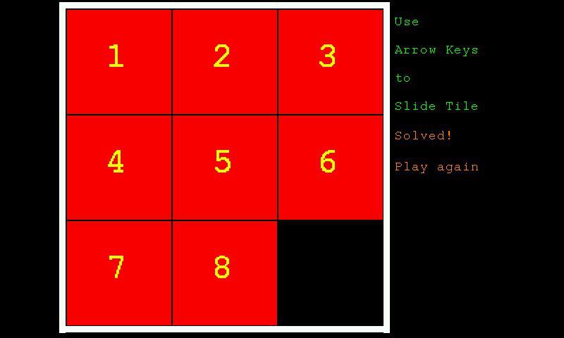 ~ Edited 2021-04-23 12:52 by lizby PicoMite, Armmite F4, SensorKits, MMBasic Hardware, Games, etc. on FOTS |
||||
| The Back Shed's forum code is written, and hosted, in Australia. | © JAQ Software 2026 |
