
|
|
Forum Index : Microcontroller and PC projects : A SNES controller modification project
| Author | Message | ||||
| Mixtel90 Guru Joined: 05/10/2019 Location: United KingdomPosts: 5727 |
No prob, Tom. I'm not going to sort PCBs out until I've compared the innards of these other USB ones anyway. I have a horrible feeling that the SMES mouldings will vary on the inside and it may not be easy to guarantee that a particular type will be available. It may require some sort of creative engineering! There are certainly a lot of the USB variety around. I considered changing the board in the NES controllers too, but they are pretty horrid inside and I'm a bit doubtful as to whether it would be worth it. The PCB is even thinner. I measured it at 0.95mm SRBP. Very cheap & nasty. I'm only going a little off-piste. Just combining two projects while I'm at it because my I2C controller hasn't got a case. :) Mick Zilog Inside! nascom.info for Nascom & Gemini Preliminary MMBasic docs & my PCB designs |
||||
| lizby Guru Joined: 17/05/2016 Location: United StatesPosts: 3015 |
A new term for me: "Of snow that has not been compacted by overuse; tends to be more exciting but less regulated and more dangerous". PicoMite, Armmite F4, SensorKits, MMBasic Hardware, Games, etc. on fruitoftheshed |
||||
| Mixtel90 Guru Joined: 05/10/2019 Location: United KingdomPosts: 5727 |
Hmmm... I've just received the pair of USB "SNES" controllers tat I ordered from ebay. One didn't have all the buttons working so it had to come to bits, didn't it? Pics later. Suffice to say it's nothing at all like the one that Tom provided and I doubt if I could make a PCB that would work in both housings. I'll experiment later. EDIT: Pictures. 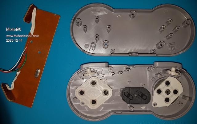 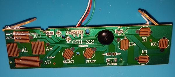 The colour is different, but that doesn't matter. They are sufficiently different inside to prevent any standardisation of PCB, I think. I'm really not certain what to do about the SNES controllers Tom. I've just compared two mouldings that are similar on the outside but completely different inside - no way to make a single PCB that will fit both as the "shoulder" buttons are completely different. It would mean producing a different PCB for each variation of case, and you don't know what it's going to be like inside until you open it. PZee Control is coming along. I might propose it as some sort of standard in future: Use with PC by using USB keyboard emulation. Uses Circuit Python, not MMBasic. Use with I2C by default, with lead terminated in RJ14 plug. Use as SNES by closing a solder blob link to change the software mode (not written yet). Plug could be DB9F to suit Atari-style connector. All using the same PCB. Pretty easy assembly. 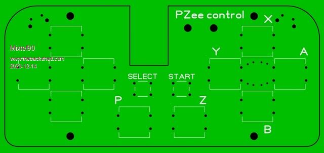 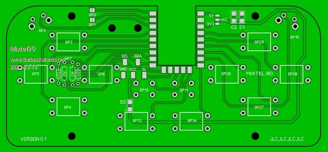 Single-sided PCB with up to 14 switches. The notch takes a RP2040-Zero surface mounted from the back. All this is currently in the design stage. Edited 2023-12-14 23:41 by Mixtel90 Mick Zilog Inside! nascom.info for Nascom & Gemini Preliminary MMBasic docs & my PCB designs |
||||
| Mixtel90 Guru Joined: 05/10/2019 Location: United KingdomPosts: 5727 |
Right, back to the SNES controller. :) Things have progressed a long way. Here are the old and new PCBs compared: 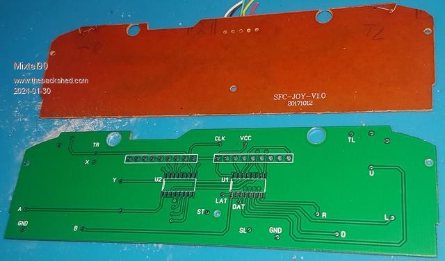 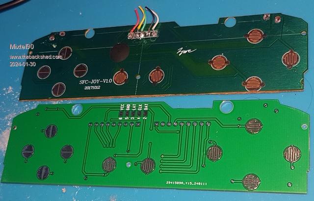 And mounted in a controller housing: 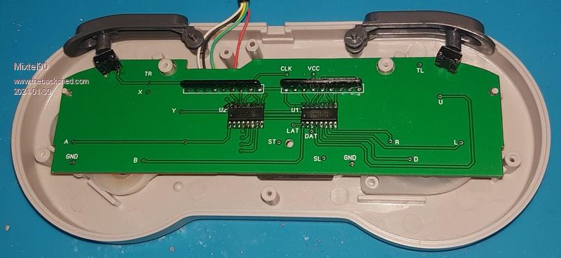 These were prototype boards so problems were expected. However, there weren't many. There are three tiny location holes that needed to be opened out from 1.5mm to get things to fit. Also, (silly mistake) the tactile switch holes were vias rather than component holes so they were too small. They had to be drilled out and some nasty soldering done. This was awkward and, if anyone wants to try this, please use the updated gerbers that I'll be posting. I recycled the lead and tactile switches from the original board. I started by getting all the holes sorted out and did a dry run to make sure the board would fit and that the case halves could be put together with it in. The next stage was to solder the SMD chips, then the resistor packs. Finally came the fight with the tactile switches. 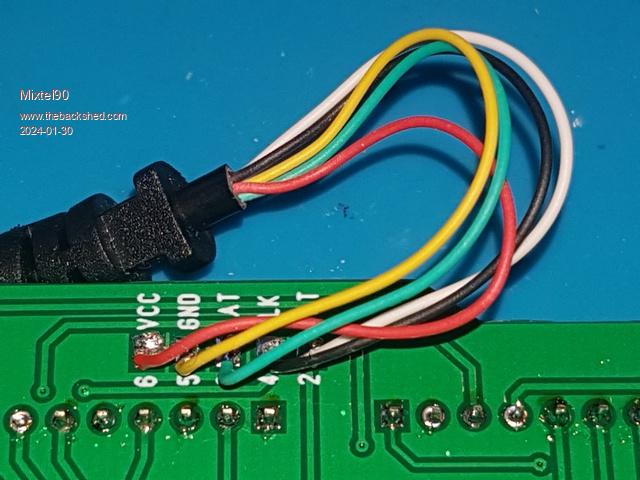 Finally, you'll be pleased to know that everything worked first time. :) I'll tie up any loose ends in a follow-up post then that's about it. Mick Zilog Inside! nascom.info for Nascom & Gemini Preliminary MMBasic docs & my PCB designs |
||||
| thwill Guru Joined: 16/09/2019 Location: United KingdomPosts: 3841 |
Hi Mick, Looks good, thanks for persisting with this for me, even if it is only entertaining you and me. Best wishes, Tom Game*Mite, CMM2 Welcome Tape, Creaky old text adventures |
||||
| Mixtel90 Guru Joined: 05/10/2019 Location: United KingdomPosts: 5727 |
No problem. :) As I said at the beginning, I couldn't resist the challenge. lol Mick Zilog Inside! nascom.info for Nascom & Gemini Preliminary MMBasic docs & my PCB designs |
||||
| thwill Guru Joined: 16/09/2019 Location: United KingdomPosts: 3841 |
Casts resurrection spell on thread. Hi Mick, FINALLY managed to get back to my electronics workbench. I would like to get the SNES controller conversion using your original board (not the updated gerber) working. So how did you do these tac-switches, it looks to me like if I naively drilled out the incorrect vias I would be in danger of the leads on the switches short-circuiting between the track to the IC and the ground plane ? Best wishes, Tom Edited 2024-03-30 01:07 by thwill Game*Mite, CMM2 Welcome Tape, Creaky old text adventures |
||||
| Mixtel90 Guru Joined: 05/10/2019 Location: United KingdomPosts: 5727 |
As a picture is worth a thousand words, here's over 4000 words-worth for you. :) First get the board to fit. The little lotating holes aren't bang on and you'll need some creative nudging with a little drill or some needle files. They aren't a massive way out, but the two outside end ones are both slightly too far in. All four holes for the button switches are too small and have to be drilled out. These are plated holes so conduction between the board sides is lost. 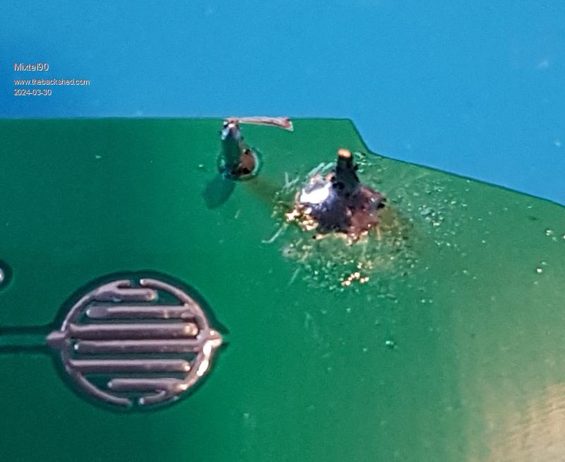 The huge blob on the right is the GND pin. You have to scratch away the solder resist. Soldering onto that much copper is bad - it conducts the heat away. Unfortunately when you drill out the hole you lose the thermal pads. Apart from that this side isn't too bad. 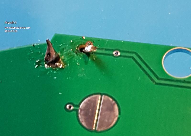 A bit more tricky. GND is on the left this time and that's a truly horrid joint. lol The signal line loses its pad so you have to scratch the solder resist again and blob the short switch pin onto it without it shorting to GND. The solder resist helps here if you avoid scratching it off the GND copper. 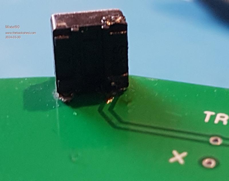 This is the other side of the board from the first pic. If you look back at that you'll see that the signal pad is isolated. It is actually on the switch side as you can see in this pic. You need to scratch the resist again, tin it, insert the switch and blob it from the track side as shown here. 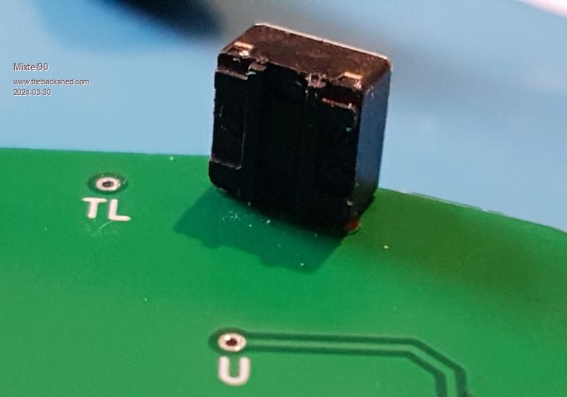 This is the other side of the board from the second pic. As both connectiions are on the other side this one is ok. It's a bit fiddly to do but it's definitely possible. The switches are still supported by mouldings from the back so I don't think much strength is being lost. Mick Zilog Inside! nascom.info for Nascom & Gemini Preliminary MMBasic docs & my PCB designs |
||||
| thwill Guru Joined: 16/09/2019 Location: United KingdomPosts: 3841 |
Thanks Mick. Following that guidance (and helped by the fact that I have new R/A switches so have some leads to play with) I've managed that, will probably add a dab of hot snot behind the switches when everything confirmed to be working. The rest of it will have to wait until tonight/tomorrow. Best wishes, Tom Game*Mite, CMM2 Welcome Tape, Creaky old text adventures |
||||
| Mixtel90 Guru Joined: 05/10/2019 Location: United KingdomPosts: 5727 |
Careful with the hot snot. The rear supports are moulded into the bottom cover and you don't want to prevent it from fitting. The length of the buttons is pretty critical too. Have fun. :) Mick Zilog Inside! nascom.info for Nascom & Gemini Preliminary MMBasic docs & my PCB designs |
||||
| thwill Guru Joined: 16/09/2019 Location: United KingdomPosts: 3841 |
Thanks Mick, Worked first time ... took longer to get the chassis together than to solder the 2 ICs and the resistor packs. Pity the controller is a bit "rattly"; I think it's the buttons as when they are all depressed it is quiet. I guess with the PicoMite's USB support this sort of controller is probably going to be redundant going forward, but still it's nice to finally have a working SNES controller without having butchered the cable on a real one. For my records did you ever publish "fixed" gerbers, and if so can I have a copy ? Best wishes, Tom P.S. I forgoed the hot snot. Edited 2024-03-30 08:30 by thwill Game*Mite, CMM2 Welcome Tape, Creaky old text adventures |
||||
| Mixtel90 Guru Joined: 05/10/2019 Location: United KingdomPosts: 5727 |
I can't remember if I did or not now. I think I'd have put them in this thread. I can probably sort some out anyway. When you've had the case to bits a few times you start to get the hang of holding all the bits together while you get a screw in. :) Mick Zilog Inside! nascom.info for Nascom & Gemini Preliminary MMBasic docs & my PCB designs |
||||
