
|
|
Forum Index : Microcontroller and PC projects : Pico Computer 3 - One board to rule them all
| Author | Message | ||||
| matherp Guru Joined: 11/12/2012 Location: United KingdomPosts: 11479 |
Here is an update to the HDMIUSB board SCH_Schematic1_2026-06-13.pdf 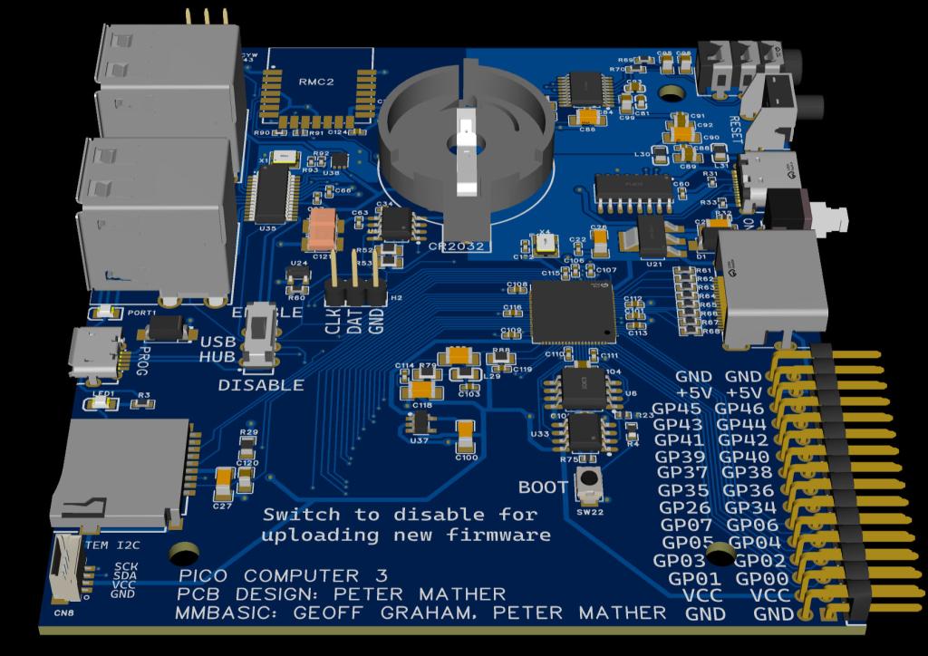   This is configured using OPTION RESET PICO COMPUTER 3 with the 6.03.00 firmware (RC18 onwards. This configuration applies to every RP2350 build. In the case of VGA builds you can use a little PCB adapter to connect to the I/O port. 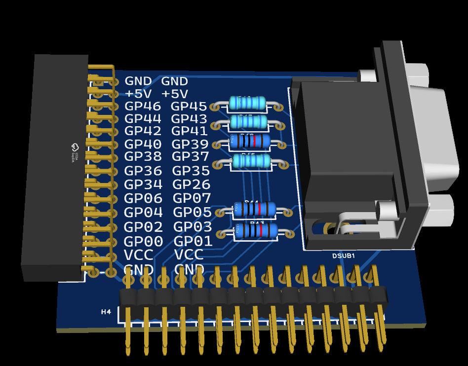 In the case of the WEB and bluetooth builds it uses the official Raspberry Pi RM2 (RMC20452T) wireless module which effectively makes the board a super RP2350B Pico2-W I've been using a first prototype to test the new HDMIWEB build and all looks good. Note that I've simplified the DVDD supply by using a fixed 1.3V regulator which works perfectly up-to 396MHz and the board now includes a 4 Pin JST-SH Cable (Qwiic, STEMMA QT, Qw/ST) connector to allow modules to be chained off it if required. I've also replaced the p-channel mosfet which switched the USB host 5V rails with a proper higher power but current limiting switch. As before the board provides I2S audio has a DS3231 RTC and all the usual goodies. I'm waiting on a second prototype that has a trivial pin usage change and assuming all good will then release the gerbers. Cost for a board fully populated other then the RM2 module (JLC/LCSC don't yet stock it, but they did do the PCB layout for me) is about USD45 each in 5-off quantity Edited 2026-06-13 21:40 by matherp |
||||
| lizby Guru Joined: 17/05/2016 Location: United StatesPosts: 3778 |
With PSRam. Super indeed. How solderable is the Wifi module? Any suggestion from JLC that they will stock it? If any in Canada want some, I would be interested in placing an order and selling 3. Or buying 2 from someone who places an order. PicoMite, Armmite F4, SensorKits, MMBasic Hardware, Games, etc. on FOTS |
||||
| grumpyoldgeek Regular Member Joined: 30/07/2018 Location: United StatesPosts: 53 |
Beautiful. I want two of them. |
||||
| matherp Guru Joined: 11/12/2012 Location: United KingdomPosts: 11479 |
The RM2 is solderable by hand. The pads extend a bit beyond the outline of the device and it has solder pad cutouts like the Pico. However, the easy way is a bit of solder paste and a heatgun - all done in 10 seconds |
||||
| jvanderberg Regular Member Joined: 06/05/2026 Location: United StatesPosts: 79 |
That looks lovely. How's the USB hub work? I will take a look at how you do the 1v1 rail because I hate their precious inductor, and having adjustable voltage really has little value unless you care about power consumption. |
||||
| robert.rozee Guru Joined: 31/12/2012 Location: New ZealandPosts: 2527 |
hi Josh, right above the first image in the top posting from Peter is a link for downloading a PDF of the schematic. it uses a TLV70313DBVR which is a 300mA LDO linear regulator providing a 1.3v output. this feeds directly to DVdd on the RP2350. cheers, rob :-) Edited 2026-06-14 14:31 by robert.rozee |
||||
| jvanderberg Regular Member Joined: 06/05/2026 Location: United StatesPosts: 79 |
Yep, I saw the schematic, thus 'I will have to take a look.' Thanks. |
||||
Grogster Admin Group Joined: 31/12/2012 Location: New ZealandPosts: 9975 |
He's at it again, folks!     Looks good. I like the idea of native HDMI, but you can have VGA via the wee external adapter board if you want. That covers all the bases very nicely, I think!  Smoke makes things work. When the smoke gets out, it stops! |
||||
| Mixtel90 Guru Joined: 05/10/2019 Location: United KingdomPosts: 8899 |
Of course, you could probably make an adapter to fit the HDMI output to give vga via a suitably tweaked resistor network. You have 8 GPIO pins you can toggle when the HSTX isn't being used. You can subtract 220R from each VGA resistor. Mick Zilog Inside! nascom.info for Nascom & Gemini Preliminary MMBasic docs & my PCB designs |
||||
| phil99 Guru Joined: 11/02/2018 Location: AustraliaPosts: 3285 |
That is an excellent idea Mick. And two more GPIO as a bonus! |
||||
| matherp Guru Joined: 11/12/2012 Location: United KingdomPosts: 11479 |
You mean like this SCH_Schematic1_2026-06-14.pdf 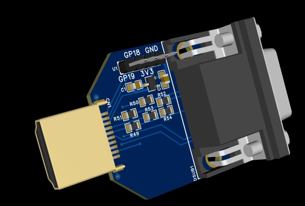 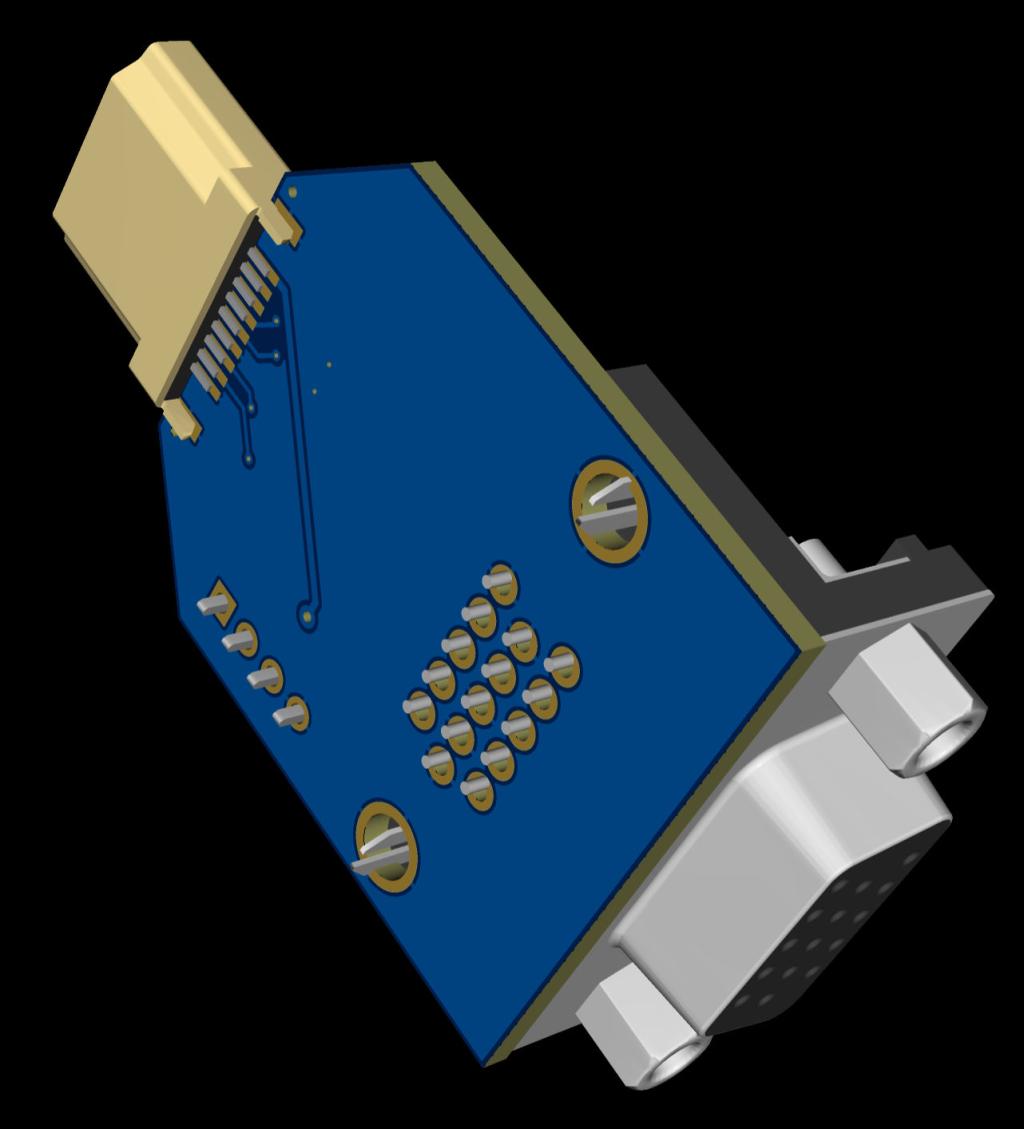 |
||||
| Mixtel90 Guru Joined: 05/10/2019 Location: United KingdomPosts: 8899 |
Nice... Or an option to use the other GPIO pins to get RGB222 (memory allowing). ;) Mick Zilog Inside! nascom.info for Nascom & Gemini Preliminary MMBasic docs & my PCB designs |
||||
| javavi Guru Joined: 01/10/2023 Location: UkrainePosts: 561 |
It is possible to make a palette switch for the VGA video output adapter 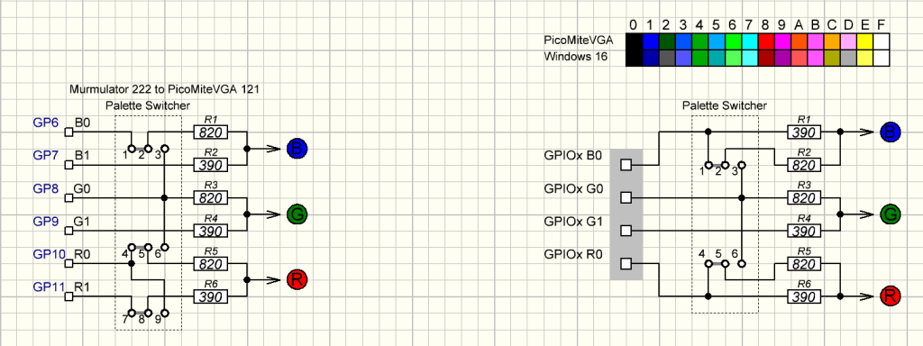 By the way, the VGA adapter doesn't necessarily have to be external. You can create a series of HSTX pins on the board and connect the VGA adapter board to them when needed. Moreover, you don't even have to disconnect it; experience has shown that the connected VGA resistor matrix doesn't affect the HDMI video output. Edited 2026-06-14 21:58 by javavi |
||||
| Volhout Guru Joined: 05/03/2018 Location: NetherlandsPosts: 5922 |
Javavi, Note there is already 220 ohm on the HDMI main board. You have to adapt resistor values, which rules these jumperable options out (outputting pure blue will feed back into R and G). Volhout Edited 2026-06-15 00:43 by Volhout PicomiteVGA PETSCII ROBOTS |
||||
| Mixtel90 Guru Joined: 05/10/2019 Location: United KingdomPosts: 8899 |
You can't "create" HSTX pins anywhere, they are fixed in hardware and are non-defineable. You can, with some risk, parallel them to other pins but it's not recommended due to the very high frequencies involved. You might get away with it, you might not. There's no need to do it anyway. We have a standard connection for VGA on the PicoMite, adding alternatives introduces software compatibility issues with PicoMite software which are best avoided. As we are designing a socket adapter, not a VGA output, the 220R series resistors are fixed and there is no direct access to the HSTX pins. Mick Zilog Inside! nascom.info for Nascom & Gemini Preliminary MMBasic docs & my PCB designs |
||||
| The Back Shed's forum code is written, and hosted, in Australia. | © JAQ Software 2026 |
