
|
|
Forum Index : Microcontroller and PC projects : Hardware Standards
| Page 1 of 3 |
|||||
| Author | Message | ||||
captainbill Newbie Joined: 16/06/2011 Location: United StatesPosts: 37 |
Howdy Don and other Maximite designers and merchants. The early users of this forum are witnessing the likely birth of a phenomenal amateur, hacker, and professional developer system. It has so much power and I/O capability, its uses and usefulness will be amazing. I have been an Arduino hobbyist for a few years now. It has been connected to user generated boards for things from UAV autopilot to videogame systems. One of the beauties of Arduino has been the plugin shields. This is a completely standardized, widely accepted form factor. Both protoboard shields and turnkey hardware shields are available. Even later Arduinos with more pins and power can connect to and support early shields. I realize the commercial considerations of first to market are huge. However, I am adamant in believing that we MUST arrive at consistent standards. To let the process be splintered into a "Beta/VHS War" standards competition will ultimately be counterproductive for the Maximite's potential for greatness. I appreciate the concept of letting the marketplace vote with its dollars but I personally hope we can arrive at standards through thoughtful discussion, negotiation and cooperation between you hardware gurus who will make this happen. Geoff has called for software guys to write their addons in a modular fashion so that the best and most need additions could be easily incorporated into later "official" versions. He has said that the basic structure of MMB is fixed. We have the fundamentals of a nice software standard. I hope we can have similar success with hardware addons or even later versions of the Maximite itself. Say 100 pin PIC version. The success of the Arduino platform is amazing. If we are smart, careful, and cooperative we can have equal or even greater success with Geoff's marvelous invention. Geoff,I salute you. I hope our collective future is as bright as your beginning. Bill Old school. Still interested. Head in the clouds. |
||||
donmck Guru Joined: 09/06/2011 Location: AustraliaPosts: 1314 |
G'day Cap'n Bill. Has that board arrived yet? I can only fully endorse your comments on Geoff, and the Maximite. Software: I saw what Geoff said about the programming being modular so that any enhancements can be easily added to the software. It did worry me that users could go about things willy-nilly, and in fact be counter productive unless the thrust was suitably choreographed. Hardware: There are only two people, or groups, to date getting involved in hardware with a view to marketing as far as I can see. These are Rohan Hamer and myself. I guess I am the one trying to lead a charge into hardware design on this Forum, and gain a consensus of opinion regarding that direction. This has been hard to do. Polls aren't cutting it so far. In fact, I seem to be getting further with the polls I have been running for the software wish list, as Geoff is eating into the wishes, and the Country and Age polls are giving some very interesting results, so I will possibly run these two polls indefinitely. Getting back to the hardware, I am almost to the point of coming up with a multi-purpose prototype board, but when I woke up this morning, I discovered a serious flaw with it, so I need to sit down with myself, and maybe a few friends, and see if I/we can over come it. Arduino Arduino has been so successful, I grabbed a few from Sparkfun and am into selling my second bunch now, but for Australia, I must admit, they have been slow sellers. My estimate is that Maximite will be fast by comparison. Altronics have already proven this. Now this is where I will show my complete lack of understanding of what an Arduino plugin shield is. Bill, in less than 100 words, can you please explain the Arduino modular shield principle for the benefit of the group and myself, so we can perhaps head in a similar direction. As I say, I am young, I can change. 
Must run, Nascar Sprint Cup is about to start. 
Cheers Don... https://www.dontronics.com |
||||
| captainbill Newbie Joined: 16/06/2011 Location: United StatesPosts: 37 |
Howdy Don The Arduino is a small 2.1" x 2.7" circuit board. Along the edges on top of the board are raised female .1" pin headers. Two rows of parallel pins, one one along each edge. Arduino power, ground, and I/O pins are available at these headers. Arduino expansion boards, called shields, stack one upon another like pancakes. On the bottom of the shields male pin headers protrude downward so the Arduino and shield are joined physically and electrically. Shields often have female headers on their top surface to allow other shields to be attached like a stack of pancakes. This arrangement is both standardized and quite compact. Shields often have the same dimensions as the Arduino, although some can be larger to accommodate larger circuits. Bill Old school. Still interested. Head in the clouds. |
||||
| donmck Guru Joined: 09/06/2011 Location: AustraliaPosts: 1314 |
Thanks Skipper, I mean Cap'n, First off, I know Geoff is designing a Mini-Max board, so whatever I do, I need to run whatever we come up with, past him before we proceed with any design. I think I get it. I'll try and paint a picture and you tell me if I am wrong. Q1) Do we call it a shield? I would like to come up with something silly, and very OZ, like a Vegimite Sandwich. :-) I grabbed one of my SparkFun Arduino boards out of stock. The first thing I did was plugged a SparkFun mini USB board into it. Standard Maximite to Shield. To do this with a Maximite would mean making up a mini-Max, or Maxi-max with a suitable footprint to match this structure. Once you set out your shield footprint, all shields will match the same footprint, but don't need to be the same size or shape. Do we need other signals from the Maximite to the shields, apart from the 26 pin (23 signals) I/O header? This may be a problem if we do. We have a Maximite with a 26 pin I/O header coming out at right angles. To match this in with a Maximite-shield (Vegimite Sandwich?), we would have to have an adapter board shield. Perhaps instead of wasting it as an adapter, we throw LEDs and switches at it. This is just to get from standard Maximite to the shield. Shield Structure Different processors so the pin out will be different. As an example, say we run 13 male pins up the top edge of the board, and 13 male pins down at the bottom edge of the board. Basically slitting the I/O pattern Geoff has come up with. Set out as the same 2 x 13 (26 pins) pattern, as when you look at the back of the Maximite case. Say the board is 6cm square, that is close to the dimensions of the Arquino platforms. Now just to get his straight, the female pins point up, and male down, correct? So on a shield, you would have 13 male pins up, on the top of the board, and 13 male pins down on the bottom of the board. This means at .1" in from the female pins, you have male pins pointing down? If this is right, then the Micro board would only have male pins up, and can only ever mount on the bottom of the stack? Does this mean that a 10cm board would have the 6cm platform footprint. It would look strange sitting on a 6cm micro board, but if that is the way to do it, fine. I have questions about signal addressing using this stack, but I'll leave that for now, and I have many other questions, but see if I am heading in the right direction. Cheers Don... https://www.dontronics.com |
||||
| donmck Guru Joined: 09/06/2011 Location: AustraliaPosts: 1314 |
Think I am getting closer Bill, This gives a better view. Have a look at all pictures. http://www.batsocks.co.uk/products/Shields/TellyMate%20Shiel d.htm So they are special pins with extended lengths, and only fill one line of holes. OK, Addressing is next.
Cheers Don... https://www.dontronics.com |
||||
stuarts Senior Member Joined: 15/06/2011 Location: AustraliaPosts: 199 |
Just looking at the shield that Don has used as an example brings up an important point. It makes the comment that it uses the Arduino's Tx line to send data to the video shield. Its obvious that before a hardware standard can be settled on for shields/vegemite sandwiches, there needs to be a software standard to define what signals are presented on what pins. To some extent this is controlled by what internal PIC peripherals are available on what pins. To make the shield concept work may also mean that where a PIC pin may have multiple functions available, we may have to decide on just using one of them for any particular pin to make sure that any available shield will always work with other shields. Since we already have the 26 pin header, would it make more sense rather than redesigning the Maximite, to provide a shield motherboard that plugs onto the 26 pin header and then provides the correct hardware base to connect the shields to? This needs much more thought. Time is nature's way of keeping everything from happening all at once. |
||||
| donmck Guru Joined: 09/06/2011 Location: AustraliaPosts: 1314 |
I think what Bill has come up with is very exciting, but we need Geoff's direction on which way he may choose to go, so we can define the bus. I have cables, and jumpers on order, but now I am looking at these Arduino header pins. But as I say, dealing with some of the Chinese, I may end up with a palette load of dog biscuits. (Insert woof icon here) I sent Geoff an Email, as soon as I realized what Bill had kicked off. Same one I sent you and a few others Stuart. Cheers Don... https://www.dontronics.com |
||||
elproducts Senior Member Joined: 19/06/2011 Location: United StatesPosts: 282 |
Having a means to connect Arduino shields to Maximite would bring more hackers/hobbyists together. Trying to make all the Arduino pins match the Maximite PIC pins will be tough. It would be better to map the Maximite software to the chipKIT UNO32 and/or MAX32 pins so these PIC32 based Arduino compatible boards could just be reprogrammed as Maximite boards. I'm not sure how much work that would take but would make the hardware easier in long run. For more info on chipKIT boards visit: http://www.digilentinc.com www.elproducts.com |
||||
| donmck Guru Joined: 09/06/2011 Location: AustraliaPosts: 1314 |
Thanks Chuck. I am sure you are right with turning other boards into Maximite systems, than doing it the other way around. But I think most users of this group, would prefer to see the current Maximite platform being used with as many I/O boards as is possible to use now. I am just getting familiar with Arduino as from today, so I am wondering if some smart bugger out there, with lots of time on his hands, can match up the Arduino shield foot print with the maximite I/O so that is is as compatible as we will ever be able to get it, and not blow up Maximite Micros, or Arduino shields. Perhaps there is someone that is so familiar, that they already know if the match can be easily done or not. Sure there are differences between AVRs and PICs, but there could be a product range ready waiting for us if we could do it this way. Adding extra Maximite signals to an additional bus would be just another header or two I'm sure. perhaps up the right hand end of the board. For those not familiar with Arduino: http://www.dontronics-shop.com/arduino-pro-3.3v-8mhz.html and Arduino shields: http://www.batsocks.co.uk/products/Shields/TellyMate%20Shiel d.htm#nogo Now all we have to do is mix them together, add some extra information from Geoff, and make us a Vegemite Sandwich. http://en.wikipedia.org/wiki/Vegemite 
Cheers Don... https://www.dontronics.com |
||||
| donmck Guru Joined: 09/06/2011 Location: AustraliaPosts: 1314 |
The 795 version has a whole bunch of additional headers, over the standard Arduino ones. 
http://www.digilentinc.com/Products/Detail.cfm?NavPath=2,892 ,894&Prod=CHIPKIT-MAX32 Cheers Don... https://www.dontronics.com |
||||
| rhamer Senior Member Joined: 06/06/2011 Location: AustraliaPosts: 174 |
Chaps, When I first looked at add on hardware I contacted both Geoff and Silicon Chip to get an understanding of what (if anything) was already in the pipeline. Geoff told me that he intended to keep the 26w IDC connector and pinout as standard (including the current reverse connector problem), and that future versions of the Maximite would have the same identical I/O connector. I have elected to use this to interface my products, for a variety of reasons, but primarily because it makes them plug and play. Short lengths of ribbon cable are cheap, easy and flexible (in every sense of the word) allowing creative housing solutions to be adopted to suit the particular need. It should also be noted however that my boards were primarily designed for actual applications, rather than expermintation. This is certinly not to say they don't make good experimenters platforms, but the driving force was permanent installation, doing real work. Regards Rohan Rohan Hamer HAMFIELD Software & Hardware Solutions Makers of the Maximite Expander. http://www.hamfield.com.au |
||||
| donmck Guru Joined: 09/06/2011 Location: AustraliaPosts: 1314 |
Was Chasps at PMG school :-) Rohan, I think your message brought back a little reality to the subject for me. I was starting to feel that it was getting too complex, and I wanted to go home, but I was already home, so I thought I may have to go to the pub instead. Gasp! I felt like Cap'n Bill being up here all night, because he had lost all four engines. (including the current reverse connector problem) Sorry, what was that? As you know, I was heading in much the same direction as you up until this morning. http://www.themaximitecomputer.com/maximite-io-board-address ing-for-bus-cable-interfacing/ Then I saw Cap'n Bill's message, and it convinced me at this point of time, to go vertical (same as Maverick and the Iceman) and just like the Arduino. Perhaps even be compatible. Then Chuck followed through with designs a little more complex that included PIC32 to Arduino. But all of those extra headers, and pins, and pin names. I figured I would have to do quite a lot of reading to get on top of it all. Then it dawned on me, we make up our own vertical stack using the same physical hardware pins as Arduino, but use our own footprint. If we want to hook up to an Arduino board, we have a 2 bob (2 bits) adapter board that converts between the two. To be fully compatible from the ground floor isn't going to work easily, and could be a bit of a nightmare to attempt to do so. So you have a cable From Maximite to a base plate that has the VSB stack (Vegimite Sandwich Bus), perhaps even cascade out to another base plate with a VSB, if you wanted to. The base plate will have the full 26 pin I/O bus and perhaps even a few spares, depending on what Geoff can let us in on. Even spares for running special signals between boards may be an option. I did this on SimmStick. And if you want to go and fit Arduino plugin shields, then you have this simple adapter. You have a VSB stack, followed by Arduino plugin shields. Simple? It will allow us to get on with designing a few boards if we can settle on this. Cheers Don... https://www.dontronics.com |
||||
Bill.b Senior Member Joined: 25/06/2011 Location: AustraliaPosts: 244 |
Hi All below is an extract from the PICAXE website for there shield board using a PICAXE 28x2 "The PICAXE-28X2 shield base has been designed to be compatible with almost all 'shield modules' as used with the Arduino system. This allows use of the various third party shields (Ethernet, MP3, Motor controllers) etc. with the PICAXE-28X2 microcontroller system, programming in BASIC. The PICAXE-28X2 chip is included with this purchase. This pack also includes a free AXE405 proto shield PCB for experimentation. This is the pre-assembled version, also available as a self assembly kit (AXE401KIT)." In the interests of the environment, this post has been constructed entirely from recycled electrons. |
||||
| donmck Guru Joined: 09/06/2011 Location: AustraliaPosts: 1314 |
Thanks Bill, I am still trying to work out how they are doing individual board addressing. Pictures on that site aren't great. It appears you can get 6 pin and 8 pin headers more readily than others. 8 pin stacking shield header: http://www.techsupplies.co.uk/epages/Store.sf/en_GB/?ObjectP ath=/Shops/Store.TechSupplies/Products/CON061 
So if you were to design even a non standard bus, it would pay to build it out of 6 and 8 pin headers it would appear. There are spaces between 6 and 8 pin headers. The 6 pin groups have a .1" space in the middle, the 8 pin groups has it wider? Really keyed so you don't stuff it up. And here is the schematic of the Arduino Pro. Was is AREF on the atmega168? http://www.sparkfun.com/datasheets/DevTools/Arduino/Arduino- Pro.pdf Well that is interesting. 20 I/O lines on the Arduino, and 20 on the Maximite Hmmmm... I just got onto my Chinese cable lady. 1.how long about the contact? 2.how long about the pins? 1. I assume that is the length of the black header section. 2. I assume that is the length of the pins. Cheers Don... https://www.dontronics.com |
||||
VK6MRG Guru Joined: 08/06/2011 Location: AustraliaPosts: 347 |
I haven't read all the posts in this topic yet but i just wanted to add a crazy idea. Why not have two Maximites!  The original/updated current design and an industrial Maximite based on the Arduino. Just thinking that there is a market for a simple standalone box of fun like we already have, and an industrial version for a fully customised Maximite. (Promite) The original/updated current design and an industrial Maximite based on the Arduino. Just thinking that there is a market for a simple standalone box of fun like we already have, and an industrial version for a fully customised Maximite. (Promite)  Again, don't lose sight of the basic nature of the design and who will/is using the Maximite and what it is being used for! (I've just got up from a crap nightshift, so be gentle if this has already come up and I�ve jumped in half cocked!) Again, don't lose sight of the basic nature of the design and who will/is using the Maximite and what it is being used for! (I've just got up from a crap nightshift, so be gentle if this has already come up and I�ve jumped in half cocked!) 
Don, Maybe we call the simple Maximite the vegemite�.(maybe a bit unPC) Its easier to ask forgiveness than to seek permission! ............VK6MRG.............VK3MGR............ |
||||
| donmck Guru Joined: 09/06/2011 Location: AustraliaPosts: 1314 |
Has been close to being covered Matthew, Geoff is doing a mini-max, but he is doing it at his pace, so I am going to blend in with his wishes on this. So there is already a plan to have two versions. I feel for the time being, we look at the current maximite, and make the plans for the 26 pin header that comes out of the back of the box. The Arduino board concept only came up today, so what I feel we need to do is select what pins of the 26 pin header, go to what pins on the Arduino foot print, and we are home and hosed. If we can get Geoff to agree on these pins, I think we can go ahead with the designing for this platform. As Geoff has his own thoughts on where he is going, I don't know if this bus is going to affect the way he wants to go about things or not, so I'll have to leave it go at that for now. I still don't mind the VSB, then adapt out to the Arduino Bus (AB), but why do that if we can start off with the AB in the first place. Just needs the 28 AB signals sorted. Cheers Don... https://www.dontronics.com |
||||
| donmck Guru Joined: 09/06/2011 Location: AustraliaPosts: 1314 |
Here are a few more Arduino snippets: Arduino board: 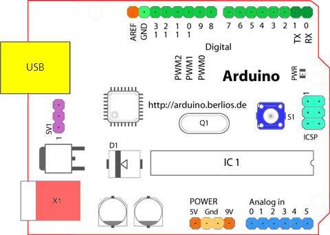
http://arduino.cc/en/Reference/Board and the hardware forum: http://arduino.cc/forum/ Cheers Don... https://www.dontronics.com |
||||
| donmck Guru Joined: 09/06/2011 Location: AustraliaPosts: 1314 |
Just had an exchange of messages with Geoff, and I have a much clearer picture of his future intentions. However as Rohan has previously stated after chatting with Geoff also, there will be no changes to the standard 26 pin I/O bus, so it is a matter of WYSIWYG. Geoff likes the idea of the stack-able boards, but his future uses and allocation of each pin, may change regarding what function each will be used for, as there may be software limitations with BASIC. So he doesn't want to, and can't support, or promise any support, for Arduino Shields. I hope I have summarized Geoff's intentions, in my own words correctly. So, if users want to try specific shields, and get them working with MM Basic, great, but this is up to them. Because of this, I really have trouble seeing why we should design the stack to the Arduino foot print layout, and push every thing we design into a footprint that may or may not be usable for us in the future. Vegimite Sandwich Bus (VSB) I don't know if I like this term or not, but like all good things, I am getting used to it. If you don't like it, You can blame me. It is a simple matter to knock up a VSB footprint adapter board, to match the Arduino bus, either as a factory made, or home made DIY device, and that I feel this is the simplest way to go. This adapter could be from the back of the case directly to an Arduino stack, or an in line adapter, that will adapt the VSB to the Arduino, so we can have the best of both worlds in future with a simple two bob (2 bit) adapter. Where we are sitting now basically is with the VSB, set out in a pattern that will reflect the I/O connector on Geoff's original article. This will be simply two rows of 13 pin Shield Stacking Headers similar to the ones show below: 
I still need the height of the black socket female section, and the length of the male tails, as my Chinese Lady (supplier) doesn't know what an Arduino is. So if anyone can help there, it would be appreciated. "FPin6L-413" It look like the tails could be .413" and not .0413"? Why this length? And have they simply put the decimal point in the wrong spot? Read the text at: http://www.solarbotics.com/products/fpin8l_413/ Arduino Footprint Also is there is a pattern for the Arduino footprint around, I would like to see that, as I do have a thought process churning around, that I would like to pursue that thought. I know this won't meet with the satisfaction of all, but I hope you can understand why I went in this direction. Thanks specifically to Bill Flora, and Chuck Hellebuyck, two of our U.S. BackShed members, for giving me enough information to reach this decision. Cheers Don... https://www.dontronics.com |
||||
| captainbill Newbie Joined: 16/06/2011 Location: United StatesPosts: 37 |
Howdy Don Maximit shouldn't be Arduino, Jr. However there are gazillions of shields available for Arduino. To make these shields usable on MM, I propose an adapter that connects to the MM connector and uses a ribbon cable to make 180deg flip back on top of the Maximite. The MM board only needs four holes for standoffs to connect to the adapter. Voila! We have a compact layout upon which to stack pancakes( my choice of terms, doesn't have any possible V-mite copyright issues). Additionsl MM pins could also be available in a layout similar to Arduino Mega. If there is ever a 100 pin MM we could bring them to an adapter. Maybe a second MM adapter on the MM board vertically above or below the current one, connected by a second set of ribbon cable to the Arduino-esque adapter or other MM specific adapters. I'm sure you hardware weenies will figure out ways to make as many MM pins as possible both available and signal compatible with Arduino shields. Obviously MM pins dedicated it its own functions won't be usable, but hopefully enough pins will be available on an adapter to operate a great number of Arduino shields. I don't want to allow the MM to be just another aruino clone. There are versions with several other Atmel processors, Arm processors, and PIC processors. There is probably one using a Pentuim or IBM 360. I'll have to google it. ;-) Some Compatibility will help to get the ball, at the risk of loosing our identity. I think arduino shields are one way. I am not necessarily for or against the arduino form factor. I just wanted to provide food for thought. Looks like I have succeeded. I just got a package from Australia. I had better open it. ;-) Bill p.s. I just returned in Dallas, Texas. They really do say y'all a lot down there. Old school. Still interested. Head in the clouds. |
||||
| donmck Guru Joined: 09/06/2011 Location: AustraliaPosts: 1314 |
G'day Bill. Glad you got your package. I'll bet you have it opened by now. Watch out for that VGA screen output, and let me know if it fires up. I am trying to imagine you as an airline pilot, and I imagine you would be more like the jovial Peter Graves type, than the Charlton Heston Type. Sorry, I watch too many movies y'all lot make. I have just printed out Geoff's and your messages. I have to go out for a couple of hours, so as Arnold would say "I'll be bark" Cheers Don... https://www.dontronics.com |
||||
| Page 1 of 3 |
|||||
| The Back Shed's forum code is written, and hosted, in Australia. | © JAQ Software 2026 |
