
|
|
Forum Index : Microcontroller and PC projects : 24 volt relays powered while MM boots
| Page 1 of 2 |
|||||
| Author | Message | ||||
pcaffalldavis Senior Member Joined: 17/10/2011 Location: United StatesPosts: 187 |
Hello all As some may remember I have a MM running a wood-fired boiler. I�m in the first season of real tests using it to heat the house. Things are going pretty well though I did run into an issue yesterday. When I designed the system I put in a number of 24 volt relays to control line power for various things like line current motors for opening and closing the fire box air intake and running a house fan. I learned early on in the test phase that in addition to the MM power switch I needed a second separate switch for the 24 volt power supply transformer. This because if the 24 volt power supply is powered on while the MM is booting the 24 volt power goes directly to the 24 volt relays and activates them until the MM takes over control about 3 seconds later. So my start up sequence became, 1) make sure the 24 volt power supply is turned off. 2) boot the MM and about four seconds later, after the MM has taken control of the relays, 3) turn on the 24 volt power supply. This worked great, until yesterday. I had a rogue reboot of the MM for no apparent reason. The genuine original MM, along with everything else in the system, is powered by a 12 volt DC lead acid battery system which also runs an inverter for line power and a 24 volt power supply. The batteries are charged by a 90 watt solar panel and a Trace 12 volt line charger when there is line power (most of the time). With an uninterruptible power supply system such as this it never occurred to me that the MM would ever reboot on its own. But it did. And when the MM had its rogue reboot the 24 volt relays were still powered and were activated for about three seconds while the MM was rebooting. This caused the Air Intake motor to rotate for 3 seconds putting it out of alignment leaving the air intake open instead of closed. After rebooting the MM program thought the fire box air intake was closed, but in fact it was open and the fire was merrily burning for over an hour before I noticed on the temperature sensor display that I had about 200 gallons of boiling water. That is about 10 degrees hotter than I like to see. This is not a pressurised boiler system and it really shouldn't be allowed to get up over 95 degrees. So I�m trying to find a way to automate the delay for the 24 volt power supply while the MM boots, sometimes unattended and by itself. I could have built another relay into the secondary component board. Maybe one that operates on 12 volts with an open circuit default, which could then control and turn on the 24 volt power supply after the MM is up and running, but the component board is full. It�s too late for such a relay on this component board, but maybe I can include a relay like that on the next component board I build for this boiler. It's always good to have spare parts and back-up components. But before I go any further down this path I thought I�d better inquire of greater minds than mine. Is there some other way to delay the powering up of a 24 volt power supply until a MM finishes booting? Is there something on the MM that once a MM program loads and starts running might be used to trip a low voltage relay that in turn might trip a 12 volt relay which could then turn on the 24 volt power supply? Something that as soon as a MM loses power might also be used to cut power to a 24 volt power supply? Others must have run into this issue of needing to keep relays from getting power while a MM boots before the MM takes control of the relays. Any thoughts or suggestions. Thanks everyone! We're all here 'cause we're not all there. |
||||
CircuitGizmos Guru Joined: 08/09/2011 Location: United StatesPosts: 1427 |
Quick question: Is the problem that during the MM boot time the outputs of the MM are set as inputs? Until your code is able to set them as outputs to drive (or not drive) your relay (through a transistor, I assume) the relays are on when you don't want them on. I haven't seen your relay circuit, but wouldn't a pull-to-ground resistor suffice to keep the transistor off until the MM is in control of the pin? Micromites and Maximites! - Beginning Maximite |
||||
| MicroBlocks Guru Joined: 12/05/2012 Location: ThailandPosts: 2209 |
Pull up or down and disconnect a part of the electronics is the way to do it so that there is always a known state. It is what makes industrial controllers special as they always be in a known state at all times. To test for those state you need to force the microcontroller in all possible modes. Cold start, warm start, uninitialised, initialised, during reset, during brownout etc.. Not easy to get all situations under control, but if it controls equipment that can be live threatening or other dangers it is necessary. Microblocks. Build with logic. |
||||
| pcaffalldavis Senior Member Joined: 17/10/2011 Location: United StatesPosts: 187 |
I think you are correct. Here is a link to a thread with the Schematic. I would have thought the resistors might have avoided this issue, but my understanding of how everything works together at different times under different circumstances is very limited. I'm inexperienced at these matters for sure. Maybe you can tell me after looking at the schematic? The 24 volt power supply is manually switched at this time as noted in my first post. If there is a way to change the 24 volt power supply so it is automatically or continually powered without triggering relays while the MM is booting, and before the relays are set as output, it would be MUCH safer and a cleaner operation/routine. Thanks for looking in. Pete in Hyder We're all here 'cause we're not all there. |
||||
| CircuitGizmos Guru Joined: 08/09/2011 Location: United StatesPosts: 1427 |
I looked at the schematic, but it is pretty small. It looks like there is a resistor on the input of the relay driver, but it doesn't look connected to ground. I can't quite see what it is connected to. Do you want to email a schematic to me? Micromites and Maximites! - Beginning Maximite |
||||
TassyJim Guru Joined: 07/08/2011 Location: AustraliaPosts: 6555 |
A better copy of the circuit diagram would help Pete. Email me or put it in a ZIP file to post here. Jim VK7JH MMedit |
||||
bigmik Guru Joined: 20/06/2011 Location: AustraliaPosts: 2981 |
Hi Pete, First a Decent schematic is needed for us to look at this for you.. But even if `most' times that the MM crashes the drive pin(s) revert to inputs, there WILL be a time when the MM actually crashes in an unknown state and the drive pin(s) will be permanently ON. Spikes or surges can cause this, of course the MM could also fail catastrophically and you may not be home to rectify the situation. I am wondering what can be done to prevent this.. Hard to say at this stage. But for the situation you have it appears to me that you dont have the MM detecting the water temp and acting on it.. What I mean is this scenario... MM Crashed and reboot causing motor to set incorrect position. MM recovers, but doesnt seem to detect that water temp is raising to a level that is too high and therefor turn the motor off or turn on another motor to close the `flue' I need a decent circuit to make a better assessment of the problem... It appears to me that you have the transistors for the motors pulled HIGH (5V), maybe that is your problem, I cant see what sort of trannies you used (they look like mosfets) Regards, Mick Mick's uMite Stuff can be found >>> HERE (Kindly hosted by Dontronics) <<< |
||||
centrex Guru Joined: 13/11/2011 Location: AustraliaPosts: 320 |
Hi Pete You appear to be using the circuit to turn your relays on and off from the May 2011 Silicon Chip article page 72. Unfortunately this circuit would appear to switch the fet transistors ON immediately on power up. You may need to use an npn transistor with a series current limiting resistor and a pull down resistor into the base connection and set the maximite to digital outputs. A high out will turn the transistor on a low will turn it off. The maximite will set all the pins to inputs until you tell it otherwise so the relays should remain off at power up. Glad to hear the system is doing what it should keeping you warm. Centrex Cliff |
||||
| bigmik Guru Joined: 20/06/2011 Location: AustraliaPosts: 2981 |
That was what I was thinking, maybe the resistors should be PULL down, but a bit more details in the schematic are needed. regards, Mick Mick's uMite Stuff can be found >>> HERE (Kindly hosted by Dontronics) <<< |
||||
| bigmik Guru Joined: 20/06/2011 Location: AustraliaPosts: 2981 |
Ok Pete! Why didn't the MM detect the temperature was getting too high and drive the motor closed? Even if it `thought' it was open it should have driven it closed. If driving the motor past a certain point might damage the mechanism then you possibly have to add a limit switch to allow the MM to determine if the air intake is indeed open or not... and if it detects it as closed set an alarm condition to make you aware of the situation. Possibly a bit of code can be added as a work around. If it does do another restart and opens the vent... 3 seconds later it should be able to recover the situation and close the vent. regards, Mick Mick's uMite Stuff can be found >>> HERE (Kindly hosted by Dontronics) <<< |
||||
| MicroBlocks Guru Joined: 12/05/2012 Location: ThailandPosts: 2209 |
The best thing to do is to make a 'closed loop' This means that when you switch on a relais you check with another port if the relais is actually on or even better if the part that is switch on by the relais is actually working. This will make a control system more robust. Hardware sometimes not do what you tell it to do. A closed loop can be made by switches, rotary encoders or a sensors. A heat sensor can also breakdown, having important parts doubled or even tripled they can prevent wrong readings. For instance in a boiler you not want your heat sensor reporting wrong values, that can cause wasted energy or far worse. Microblocks. Build with logic. |
||||
| centrex Guru Joined: 13/11/2011 Location: AustraliaPosts: 320 |
Hi Pete Just another thought perhaps you could use a NE555 as a missing pulse detector. The 555 being reset every few seconds by the main program,if no reset pulse the 555 would time out and switch of the 24volt supply or cause the various controls to return to their failsafe position. As noted in a previous post this may require microsw etc to detect the controls positions. Regards Centrex Cliff |
||||
| pcaffalldavis Senior Member Joined: 17/10/2011 Location: United StatesPosts: 187 |
All good information for me to think on. Here is a pdf of the schmatic. Maybe it will be clearer.2012-11-17_154441_WoodFired_Boiler_schematic.pdf We're all here 'cause we're not all there. |
||||
| CircuitGizmos Guru Joined: 08/09/2011 Location: United StatesPosts: 1427 |
Just a quick look (I have to run) but I think that the resistor pack for your mosfets should be connected to ground and not 5V. That would be a very minor change (move that 1 connection) and wouldn't involve adding a relay or changing a procedure. Micromites and Maximites! - Beginning Maximite |
||||
| pcaffalldavis Senior Member Joined: 17/10/2011 Location: United StatesPosts: 187 |
Bigmic; The MM does monitor the boiler water temp. That is what lets it know when to shut the air intake. But if the air intake was put off its calibration by the motor turning for a few seconds at start up, before the MM took control to keep it from turning, then the MM does not know it is not really closed. I do have a sort of low tech work around that I�ve been thinking on. During the testing phase last winter I often forgot to turn off the 24 volt transformer before I booted the MM. The result was that the chain that wraps around the air intake motor drum would turn too much during the boot and physically disconnect and tear away from the air intake plate. It would rip the plate up and away from the surface it was supposed to lay flat on when the air intake was closed. I got around this by connecting the chain from the Air intake motor to the air intake plate with a small copper wire link that was only bent over, not twisted to lock it tight. This allowed the chain to pull open the copper �link� if the motor got away from me and ran during a boot up. You have the scenario correct. The MM crashes and reboots causing the air intake motor to set in an incorrect position. I do have a routine in the program that constantly monitors the boiler water temp, but I only wrote the program to close the Air intake when it thought the Air intake was open. Never thought it would be important to close the Air intake when MM thought it was already closed. But I�m thinking of putting in another safety sub routine that always checks the water temp (Air intake open or closed) and if it gets say over 95 degrees C then turn the air intake motor three full revolutions in either direction. This would rip the copper link open, causing the air intake plate to fall or drop back down and shut off the air until the system was manually checked on later. Using this method the MM couldn�t reopen the air intake until the copper wire link was reconnected. I kind of like this plan for its safety. I also have a sub routine that monitors the water temp while the air intake is open (and the fire usually increasing). That routine monitors the water temp, and if it continues to go down instead of up, and goes down by more than 5 degrees, then the MM closes the air intake and flashes the message �TEND TO FIRE� meaning that you are either out of fuel or the fire went out. This can happen when the air intake is closed too long between cycles. This happens sometimes when the time between firings is more than six hours. To Centrex; I am using MOSFETS. I mounted them in slot receptacles so I could replace or swap them out if needed. But I don�t know if I can change them for other types of transistors. That is beyond my knowledge or level of understanding at this time. 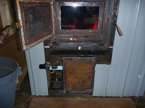
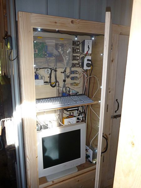
I like the idea of having a micro switch monitor the actual status of the Air intake plate. I�ll think on that too. The Air intake is open in the upper photo. Note the plate is lifted by the Air intake motor. Thanks all! I appreciate all your help. If any is interested in more pictures let me know. I don't want to waste server space unless it is of interest to others. Pete We're all here 'cause we're not all there. |
||||
| TassyJim Guru Joined: 07/08/2011 Location: AustraliaPosts: 6555 |
The mosfets should be able to be driven directly from 3.3V so simply changing the 10K resistors which currently go to 5V and tying them to ground should be all that's needed. As it stands, the Maximite pins will be high impedance at power up so the 5V supply turns the mosfets on until the MM pins are driven low. Jim VK7JH MMedit |
||||
| centrex Guru Joined: 13/11/2011 Location: AustraliaPosts: 320 |
The mosfets you are useing are logic level and should switch with only 3.3 volts on their gate. You would need to look at your software, if you have set the pins that drive the fets to open collector (cfg 9) then just changing the resistor pack to gnd wont work. You will need to change the config of the pins driving the fets to 8 (ie SETPIN 17, 8) which is the digital output mode, this will give you 3.3 volts out when the pin is on and 0 volts when off. The pictures show a very interesting project you have embarked upon, how often do you have to put wood in the fire. Cliff Cliff |
||||
| pcaffalldavis Senior Member Joined: 17/10/2011 Location: United StatesPosts: 187 |
The motor controls are configured in the first few lines in the program. One is SETPIN 20,8 and the other SETPIN 19,8. If I load the fire box full up, (takes about 3 large wheelbarrows full which is about 1/7th of a cord), it will run for about 48 hours. I have found that by putting in much less wood, like maybe 8 to 10 18" long split logs at a time, it will easily go 12 hours. Lately I've started putting in about twice that, one wheelbarrow full at a time (about 15 to 20 split logs or 1/21st of a cord) and it easily goes for 24 hours. I burn mostly spruce or hemlock. These are both soft woods, but they account for abot 90% of what we have in these parts. Oddly enough outdoor temperature does not seem to have much impact on fuel consumption. I'll know more on this as more winter data is collected. The MM reports significant daily data go the SD chip each night at midnight. Lately I've taken to loading up the firebox in the morning and then checking it in the evening. I don't usually load more wood at night. I just use a rake or hoe to stir it up and level the charcoal and logs. That way the next morning I have a fairly flat bed of burned wood and coals to load the next 24 hour's supply of wood on. The house has never been so warm, nor has it ever had such even heat. The temperature in the house never fluctuates by more than 2 degrees F (about 1 degree C) from the requested temperature. I have night and day modes with different desired temperature settings. The program could easily be expanded to create any custom temperature/time or calendar controls anyone would want. It is just so nice to have rock steady even heat after years of wood stoves in the livingroom. As most folks that have heated with wood stoves will tell you, 'When you face the fire, your front will be toasty warm and your back will be half frozen.' That is not true with hot water heat! Yahoo! We're all here 'cause we're not all there. |
||||
| centrex Guru Joined: 13/11/2011 Location: AustraliaPosts: 320 |
If you change the 10k resistor pack connection to gnd make sure all the other SETPIN configs that drive the other relays are set 8. Best of luck. Cliff Cliff |
||||
| TassyJim Guru Joined: 07/08/2011 Location: AustraliaPosts: 6555 |
With that configuration, you should be right with just changing the 10k resistors to ground instead of 5V. Certainly worth a try. At the rate you are going, all the bears will want to move in with you. Jim VK7JH MMedit |
||||
| Page 1 of 2 |
|||||
| The Back Shed's forum code is written, and hosted, in Australia. | © JAQ Software 2026 |
