
|
|
Forum Index : Microcontroller and PC projects : The new GPRS modules
| Author | Message | ||||
kiiid Guru Joined: 11/05/2013 Location: United KingdomPosts: 671 |
I had promised to a few people to let everyone know when the new GPRS modules are here. Now completely compatible with the micromite plus side plated holes for 2.54mm pitch breadboards (in addition to the standard bee headers). Actual schematic is attached here. Anyone interested, please let me know as I don't have many of these available at the moment. Thanks 2014-08-10_052235_M2Mbee_circuit.pdf http://rittle.org -------------- |
||||
| viscomjim Guru Joined: 08/01/2014 Location: United StatesPosts: 925 |
Hi Kiiid, I am super interested, can you give ordering details? I noticed you used the 170, nice touch for when Geoff releases new MMbasic for that. Can you post a pic also? |
||||
| kiiid Guru Joined: 11/05/2013 Location: United KingdomPosts: 671 |
Here is a picture 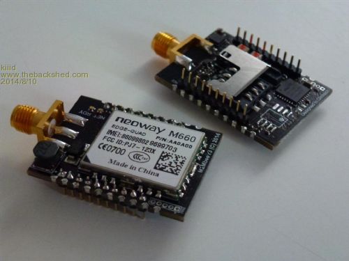
I don't have them on the website yet, but you can leave me a message or email to discuss. By the way, I've got a new module coming out soon as well. It is for control of one or two medium power brushed DC motors, and has an on-board processor with position inputs, and a few extra I/O ports. It is the smallest of its kind for this purpose and motor power. A PLCC68 socket will be everything needed outside. Placing a picture of that one too, in case anyone is interested. 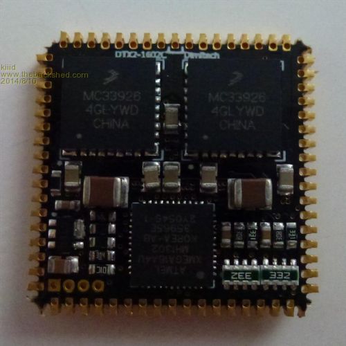
http://rittle.org -------------- |
||||
| viscomjim Guru Joined: 08/01/2014 Location: United StatesPosts: 925 |
Hi Kiiid, I just received my gsm board from you. Thanks! I am waiting on some header pins to solder onto the board for .1 spacing so I can plug into breadboard and play a bit. Am I correct in assuming that the header pins 4 and 8 are used to connect to console RX and TX? It shows on schem. that pin 8 is labeled reserved. Also, does it already have MMBasic loaded or do I need to do that? One more thing, what is the power VBAT need to be, 5v, 3.3v or other? Thanks again, can't wait to play. |
||||
| kiiid Guru Joined: 11/05/2013 Location: United KingdomPosts: 671 |
Hi, good to see that the postal services are reliable :) Since it is bee replacement, it is supposed to take 3.3v on the VBAT input. Pins 4 and 8 are the console, you have read the schematics correctly. Pin 8 shows 'reserved' because that is the labeling of the standard bee connector. I sent it to you preloaded with the MMBasic. Kon http://rittle.org -------------- |
||||
muddy0409 Senior Member Joined: 15/06/2011 Location: AustraliaPosts: 125 |
G'day. Is this a GSM band (2G) or 3G or 4G? Unfortunately, up here in the bush there is NO 2G coverage from ANY carrier, and Telstra will be shutting down their 2G network soon anyway. Apart from that, Telstra is the only network here anyway, so the 3G GPRS module from Little Bird, which is only Optus, won't work. So unless I can find a 3G or 4G module that will work on Telstra, I can't even play around with GPRS. I have seen some so called all networks GPRS modems around, but I don't have a spare arm and leg to pay for them. Just another joy of living in the middle of nowhere. Don't poo poo conspiracy theories. Remember that everything ever discovered started somewhere as a theory. |
||||
| kiiid Guru Joined: 11/05/2013 Location: United KingdomPosts: 671 |
It is a 2G modem. Unfortunately from personal experience the 3G ones and too fussy and won't work with all operators, are too large for my board, and so on. As far as my information goes, 2G in Australia won't be shut down completely but only for the mass phone user (who wants 3G anyway). 2G will remain for years but for M2M applications only, so no need to panic just yet... For the rest of the world I think this is not even planned. http://rittle.org -------------- |
||||
halldave Senior Member Joined: 04/05/2014 Location: AustraliaPosts: 121 |
@muddy0409 What about the sim908 modules. http://www.ebay.com/itm/271550337065 They are quad band and have gps built in for around $20usd |
||||
| viscomjim Guru Joined: 08/01/2014 Location: United StatesPosts: 925 |
Hi Kiiid, A couple of questions... I mapped out the pins used on your board to the pin numbers that MMBasic references for uMite 28. There is a pin from the modem labeled ADC wired to MMBasic pin 23 (analog input). Is this signal strength? If not, what do we read from this pin? There is a pin from the modem labeled ON/OFF wired to MMBasic pin 6. How is this controlled? Is it pulsed for a certain amount of time, or is it on=high, off=low? On pin 9 of the xBee connector, this pin is connected to DTR on the modem. Does it need to be high or low to operate, or does it matter? MMbasic pin 5 is connected to the RING from the modem. When a ring is detected, does this bring pin 5 high or low? I am very happy to see that you brought out console, com1, com2 and I2C on the pins. It looks like com1 is used for the modem so xbee pin 2 and 3 would probably not be used externally? This will allow for a great amount of expansion (like a 2004 or 1602 I2C display and keyboard. The whole board is very impressive for its size and having a 170 on it is great!!! Can't wait to fire it up. Just looking for a 3.3v 2amp supply right now. If anyone else is using this module, let me know if you want the map for MMbasic and I will post. |
||||
| kiiid Guru Joined: 11/05/2013 Location: United KingdomPosts: 671 |
The ADC from the modem is a normal ADC pin, but read and processed by the modem, not the pic. There is an AT command (AT+ADC from memory) which is for reading the modem's ADC. The ON pin of the modem is to allow the pic to switch the modem on or off. High level is active. You can also permanently connect the ON pit to power. If you are controlling it from the pic, there needs to be at least 800ms interval between the battery power has been applied and the ON pin set high. To switch off you will need to keep ON low for at least 400ms. Basically in both cases I have wired these modem pins to the outside connector so the module could be used without a pic at all or the pic doing something else and the relevant shared pins kept in high impedance, while the modem is controlled from outside. The same situation is valid for connector pins 2 and 3 as well - everything with the possibility of shared use in mind. In the general case when you are running the entire software in the pic, those two pins are not connected outside, or you can monitor the activity on the line through them, or if you keep the modem off, the pic's UART will remain free for other uses. As to the power supply, I have tested and the module is working fine with 3.3V 1500mA power, even a bit lower, but no need to take unnecessary risks. So far not many people from TBS have this board, because I had manufactured a very limited batch of first pre-release boards and the majority of them went to non-TBS users through other channels. However there are people here who have the boards and might be interested in your MMbasic development for it. Unfortunately due to known restrictions I am unable to provide an optimised and customised revision of MMbasic for the board, but with time I will make a FANF port for it. According to my product development plans the board will be on the market in about a month from now and will be shipped (mostly) from Europe, which will be good for EU and US customers because the shipping times will be mush shorter. Kon http://rittle.org -------------- |
||||
| viscomjim Guru Joined: 08/01/2014 Location: United StatesPosts: 925 |
Hi Kon, How about the DTR on xbee pin 9? Does it need to be active to work? Also, how is ring detected, does the modem put out a high to MMbasic pin 5 when there is a ring? Thanks for the info! |
||||
| kiiid Guru Joined: 11/05/2013 Location: United KingdomPosts: 671 |
The DTR signal is optional. If you pull it low from outside, the modem will switch to sleep mode until you release it (internal pull-up will bring it back high). The RING output is normally high and repeatedly goes low for 250ms within a 4s interval when there is an incoming ring. It also indicates an incoming SMS by going low for 600ms once. Kon http://rittle.org -------------- |
||||
| The Back Shed's forum code is written, and hosted, in Australia. | © JAQ Software 2026 |
