
|
|
Forum Index : Microcontroller and PC projects : MM2: 3.2" Colour TFT Touchscreen
| Author | Message | ||||
TassyJim Guru Joined: 07/08/2011 Location: AustraliaPosts: 5913 |
Where will it stop? By the time the parts arrive here, I will be too busy packing for a holiday so I don't think I will be doing much playing with it - but I will be watching. I am taking the BOSS to the Chelsea Flower Show and even though it's 90 days before we fly out, I have been banned from starting any new projects. Jim VK7JH MMedit MMBasic Help |
||||
Grogster Admin Group Joined: 31/12/2012 Location: New ZealandPosts: 9066 |
I didn't know you were friends with Bruce Springsteen...  Smoke makes things work. When the smoke gets out, it stops! |
||||
| Grogster Admin Group Joined: 31/12/2012 Location: New ZealandPosts: 9066 |
@ matherp - what pin is SPIOUT on the 64-pin device? ...can't find it... EDIT: Here we go, then: 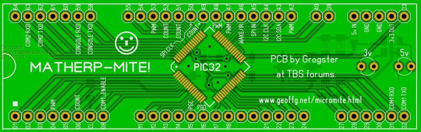
This is not quite finished, but by deleting the pin-strip pins that are doubled up or not needed, we end up with a standard DIL module, that is breadboard-friendly, and reasonably idiot-proof, in that it will only fit into a PCB one way around. On-board 3v3 regulator, with that 3v3 available on one of the pins, to power any other external 3v3 stuff, so long as it is not too thirsty. All other decoupling caps and Vcap also on-board. ...I am just waiting for matherp to tell me where SPI OUT needs to be, so I can label that pin. Unlabelled pins are general I/O, and can be input, output or analog 99% of the time. I have yet to put little silkscreen markings on the pins that are 5v tolerant, but that will be next. What do you guys think of the tongue-in-cheek name for the board? Smoke makes things work. When the smoke gets out, it stops! |
||||
BobD Guru Joined: 07/12/2011 Location: AustraliaPosts: 935 |
Hmmm, wot about Peter-MITE?  |
||||
| matherp Guru Joined: 11/12/2012 Location: United KingdomPosts: 8592 |
Sorry, missed it off the sheet, it is pin-5 (PortG7, same as on the 100-pin) Where are VCAP and other decoupling capacitors on your layout? At 96Mhz it is essential these are as close to the chip as possible. I like the ground-plane - this should help electrically. If you can fit the pull up resistor on pin 7 (MCLR), and optional pullups on 43 and 44 (I2CSDA, I2CSCL) it would make it almost completely self contained. Great work! |
||||
| Grogster Admin Group Joined: 31/12/2012 Location: New ZealandPosts: 9066 |
Thanks, matherp.  All the caps and reg are on the bottom copper. All the caps and reg are on the bottom copper.
I will add the SPI thing, and upload both layers for everyone to see. Smoke makes things work. When the smoke gets out, it stops! |
||||
| WhiteWizzard Guru Joined: 05/04/2013 Location: United KingdomPosts: 2794 |
Hi Grogs, Nice quick work!!
I too am working on some PCBs but only need to continue with one if you can consider a couple of things (also making your PCB a more 'self contained' module): 1> Please can you squeeze in a Reset switch? This can be a micro-sized one as I recommended on another thread with Lou & Zonker I believe) 2> Can you add a 5-way header to accept a USB-to-serial module? (Like BigMik does with his PCBs) I will be building an equivalent in a few hours (as soon as the PICs arrive). Still waiting for the .Hex from Peter but hopefully all will be up and running very soon. WW (PS: Skype??) PPS: I would also consider using SMD LEDs as it gives a more 'modern look & feel (just my opinion though!). I know you would need a few more via but this is not an issue for a PCB fab house! For everything Micromite visit micromite.org Direct Email: whitewizzard@micromite.o |
||||
| Grogster Admin Group Joined: 31/12/2012 Location: New ZealandPosts: 9066 |
Hey there Phil.
Re. #1 - Yep, I can put one of those tiny little SMD tact switches in there - will add. Re. #2 - Yep, can do that too - will add. Can you link me to the module? Re. Skype - Yep, not forgotten, just have not got to shops for new Skype phone - will do this next week. Re. LED's - Yep, you're right. With everything else being SMD, I might as well make the LED's SMD too - will change. Smoke makes things work. When the smoke gets out, it stops! |
||||
| WhiteWizzard Guru Joined: 05/04/2013 Location: United KingdomPosts: 2794 |
G, Link to thread regarding switch. Also; Please can you start a new thread . . . . .
For everything Micromite visit micromite.org Direct Email: whitewizzard@micromite.o |
||||
bigmik Guru Joined: 20/06/2011 Location: AustraliaPosts: 2870 |
Grogs, As your board is already in the 100mm panel size. Have you considered making it a bit longer and a bit skinnier. . That would have two benefits, firstly you could get 7 boards per 100mm panel (maybe 8 with a tight edging) and they would plug into a breadboard and not take up too much in the way of `holes' real-estate on the breadboard. Your board looks to be 0.8" between top and bottom row.. my idea is to reduce this to 0.4". This is a VERY rough mock-up of what I am suggesting. Track layout would be tight but I calculate 0.01" tracks with 0.01" clearance should work on 2 layer boards. Of course you could go to 4 layer as well. Just a thought. 
Regards, Mick Mick's uMite Stuff can be found >>> HERE (Kindly hosted by Dontronics) <<< |
||||
| MicroBlocks Guru Joined: 12/05/2012 Location: ThailandPosts: 2209 |
I like the skinny pcb shape a lot. Reminds me of the pcbs that could be used in the simm sockets. However i do have to use considerable force to put in and take out a UBW32 from a breadbord. Very similar in length. I think it will only work well when the pcb is thick (1.6mm) and strong to withstand the forces. having the chip in the center causes the forces to be concentrated in that area. The rest is 'reinforced' by mounting the connector strips. Microblocks. Build with logic. |
||||
| Zonker Guru Joined: 18/08/2012 Location: United StatesPosts: 761 |
Humm... I wouldn't mind laying out a PCB for this fantastic new motor, but I think I would like to have it connected to the back of the 3.2" display with proper I/O out the backside... What display would be available that would stay the same for awhile... I mean, if we lay out for a certain type of display unit, are we still be able to source the same unit a year from now... not sure, there are many types of units out there... will they stay the same... not sure... OR, can we source just the "raw" display itself and solder the flex-strip on to the MPU board directly, thus avoid having different kinds of display backer boards to deal with... Thoughts on this... Also, after we get some hardware "settled in", are we going to take the programs to the next level... I mean, create "GUI" objects like we have on the TFT Maxi-Mite..? (sliders, buttons, yes-no boxes) ect... All food for thought..... |
||||
| matherp Guru Joined: 11/12/2012 Location: United KingdomPosts: 8592 |
Here is a version of the code for the SSD1289 3.2" display that runs on the 100-pin Micromite++. It uses the 16 PortB pins so the program can write the complete data word in one instruction. The fastest I can get it to run is 72Mhz - above that the processor is too fast for the display 
At 72Mhz it take just 6msec to write the complete display in single colour e.g. T32.fillscreen(red). That represents 320x240x16 bits of data = 205Mbps 
2015-02-01_141036_T32-100.zip |
||||
| WhiteWizzard Guru Joined: 05/04/2013 Location: United KingdomPosts: 2794 |
Hi Peter, I am having problems with my email at the moment and your post just now touches on what I was asking in the unsent email. Hi Peter, I need to ask you a quick question about display interfaces. In your opinion, with a TFT (or OLED) driven by a MX470, would a 16-bit interface refresh the screen faster or slower than a SPI display? Lets assume a 3.2" for now but same question for a 1.5 and a 2.4 screen. Also, by what factor of increase is one over the other, i.e. twice as fast, ten times faster, etc. Finally, with the 100pinner MX470, how many MMBasic PWM outputs are there? I know the MX150/170 have five outputs on two channels, but then I see ten PWM outputs listed in the pin listing diagrams you posted. Any info here would be appreciated. Thanks. WW For everything Micromite visit micromite.org Direct Email: whitewizzard@micromite.o |
||||
| matherp Guru Joined: 11/12/2012 Location: United KingdomPosts: 8592 |
The fastest SPI will run is 20Mbs with the chip at 80Mhz (peripheral bus speed /4). At 96Mhz this drops to 12Mbs as the peripheral bus has an extra wait state. Given it takes 1228800 bits to write the complete display, this means SPI alone will take 61msec to update the display. As you can see the parallel interface is 10x faster without even taking into account the code needed to load the data into the SPI register and test for it being clocked out. There are only 5 PWM outputs on the 470, the same as the 170, I don't think my document shows more but apologies if there is a typo - there are 5 on the 64-pin and the same on the 100-pin |
||||
| WhiteWizzard Guru Joined: 05/04/2013 Location: United KingdomPosts: 2794 |
Thanks Peter. So parallel definately faster then
Regarding the PWM pins, that was my mistake; when you first publicised what you were up to, your pinouts just said PWM. I counted both the 64 pinner and the 100 pinner to come up with 10 undefined PWM outputs - sorry. In a later post you actually define the PWM pins - my mistake! Does the OLED module I sent you work with parallel interface too or is it just spi? If parallel too, then is it easy to modify your code to work with the parallel interface (on a 470)? WW For everything Micromite visit micromite.org Direct Email: whitewizzard@micromite.o |
||||
| matherp Guru Joined: 11/12/2012 Location: United KingdomPosts: 8592 |
The OLED module only works SPI (the underlying controller does both) and the code has been tested on both the 28-pin and 100-pin Micromite (that is how I found the bug in the Microchip trig library). Converting the code to run parallel is trivial. |
||||
| CFLY Regular Member Joined: 20/05/2015 Location: FrancePosts: 41 |
I have no success with the display TFT 3.2 ssd1289... 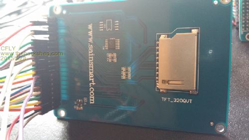
Under MkII 4.6 44 pins I have this having erased the screen... 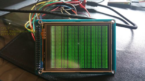
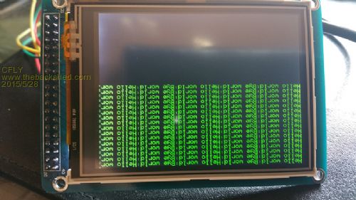
Only half of the screen is erased... And with the MkII 470 (64 pins) and this : 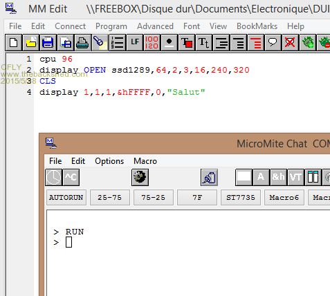
I have the scrren with : 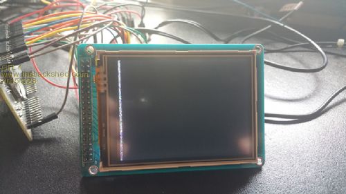
I have two screens and I have the same results on both... |
||||
