
|
|
Forum Index : Microcontroller and PC projects : Help with Barking Dogs.
| Page 1 of 2 |
|||||
| Author | Message | ||||
| Phil23 Guru Joined: 27/03/2016 Location: AustraliaPosts: 1667 |
Hi All, My 15 Year old son & I completed a Kit last night & it doesn't work. This a first in this household, never had a kit fail in the past. Can anyone help with diagnosis? Construction is perfect, he's done a great soldering job. No misplaced components. Basic things like 12V (from SLA Battery), and 5V to chip is OK, but that's where our testing has stopped. It uses a preprogramed PIC12F675. Where would we go from here to identify either dead or blank PIC etc. Test gear we have on hand a multimeter, USB Scope and a Pickit3. Thanks Phil |
||||
| Gizmo Admin Group Joined: 05/06/2004 Location: AustraliaPosts: 5185 |
No circuit, so guessing. I guess there is a signal source, the chip, and a amplifier. Use your scope to see if there is a signal from the chip, and if so, trace it through the amplifier. Glenn The best time to plant a tree was twenty years ago, the second best time is right now. JAQ |
||||
| VK2MCT Senior Member Joined: 30/03/2012 Location: AustraliaPosts: 120 |
Suggest double check values of resistors, orientation of caps that are polarised and orientation of diodes etc. What waveform do you get at the 10ohm resistors that are fed from the PIC outputs. John. |
||||
| hitsware Guru Joined: 23/11/2012 Location: United StatesPosts: 535 |
How do you know it's not working ? |
||||
| Phil23 Guru Joined: 27/03/2016 Location: AustraliaPosts: 1667 |
Can easily scan the circuit. First suspicion though is a blank PIC. Phil. |
||||
| Phil23 Guru Joined: 27/03/2016 Location: AustraliaPosts: 1667 |
To quote the documentation, from the testing paragraphs. [Quote] Press and hold the start button and connect power. The LED should flash on & off about 3 times per second. When the switch is released, the LED should begin flashing at a one second rate. [/quote] That and I can usually actually hear these devices, if not the primary frequency, it must be a harmonic. Phil |
||||
| vegipete Guru Joined: 29/01/2013 Location: CanadaPosts: 1182 |
A few connections on a bread board would allow you to use the PICKit3 to read the chip. If it comes back all 0x3FF you know it's blank. If it returns 'code protected', you know there is probably something there. Or you get a firmware dump. Just be very cautious of what buttons you press in the PICKit software - you especially don't want to hit the 'Erase Chip' button! Visit Vegipete's *Mite Library for cool programs. |
||||
| Phil23 Guru Joined: 27/03/2016 Location: AustraliaPosts: 1667 |
Gmail finally delivered my message to myself.... 3 1/2 hours after sending it. The Circuit Diagram. 2016-06-02_212803_Circuit_1.pdf All componets double checked & 5V present at the PIC. Cheers. |
||||
TassyJim Guru Joined: 07/08/2011 Location: AustraliaPosts: 6543 |
Check that pin 4 is high. Briefly pulling pin 4 low should reset the processor. Check that pin 5 is initially high and slowly goes high again after start button is released. There should be short pulses on pin 2 to flash the LED. You will need the CRO for this one and I think it should be flashing before pressing the start button. It would have helped if Altronics had given the correct edition of SC in their web site. September 12, not August 12. Jim VK7JH MMedit |
||||
| Phil23 Guru Joined: 27/03/2016 Location: AustraliaPosts: 1667 |
Thanks Jim, I've Googled a lot of Silicon Chip articles recently, looking for MicroMite & other stuff to go searching in my magazine piles. It seems like Silicon Chip themselves have quite a lot of wrong edition references listed also. There's at least 2 issues sitting in the office which are a month either side of the correct date. Cheers. |
||||
| Gizmo Admin Group Joined: 05/06/2004 Location: AustraliaPosts: 5185 |
You know, I really hate how every bloody SC project these days has to include a pic chip! This thing could have been built with 3 or 4 general purpose IC's, like 555's or op amps, and it would have been easier to troubleshoot, easier to get parts for, and you would be able to go back to it in 20 years and still trouble shoot it and get parts! Bring back real projects that teach and have a life past 2 years. Rant over. The best time to plant a tree was twenty years ago, the second best time is right now. JAQ |
||||
| Phil23 Guru Joined: 27/03/2016 Location: AustraliaPosts: 1667 |
Ditto..... |
||||
| damos Regular Member Joined: 15/04/2016 Location: AustraliaPosts: 81 |
Particularly this circuit which could have been done with a 555 and a 4017, and at the same time teach a lot about electronics. It really only needs to generate two ultrasonic outputs with a small gap to stop both transistors being turned on at the same time. I built an Oatley kit once. Can't say it really worked, as the dogs kept barking. (I checked that it worked) |
||||
plover Guru Joined: 18/04/2013 Location: AustraliaPosts: 306 |
Ok, I see that +5V is on the microprocessor, I assume this is a DC measurement. Just using a multimeter: It would not hurt measuring all pins for DC voltage. Measure on the pin to be sure. Doing an AC measurement with multimeter could reveal unexpected signal on some pin, for example you do not want this on the +5V to the micro. You may need to make sure that you measure both on the solder joint and the actual pin on the micro odd things do happen. If the micro is in a socket need to measure on the legs of the micro. If working an AC measurement should show something on the output drivers provided it can measure higher than 50 Hz of course.  |
||||
| WhiteWizzard Guru Joined: 05/04/2013 Location: United KingdomPosts: 2991 |
. . . . and do indeed check all PIC pins are actually inserted into the socket (and not an odd pin bent under the IC package and hence disconnected from the circuit). I used to run a service department for an Electronics firm here in UK where people would send their Home-Built kits that were 'built perfectly' but would not work. The two most common issues were what I mention above; and also dry joints. Good luck in finding your 'issue'  |
||||
| Phil23 Guru Joined: 27/03/2016 Location: AustraliaPosts: 1667 |
Finally got to check this out again on a rainy day...... No Wonder it doesn't work...... 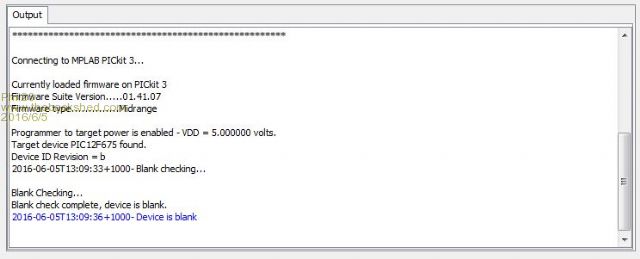
I'm sure I'm reading it correctly. Cheers. |
||||
| Phil23 Guru Joined: 27/03/2016 Location: AustraliaPosts: 1667 |
@Gizmo I'll take over the Ranting from here.... Might be time for some "Outside Time" to avoid the temptation of paying $3.00 for the firmware off SC on a Sunday... |
||||
| vegipete Guru Joined: 29/01/2013 Location: CanadaPosts: 1182 |
Since this is a learning project, now is your chance to learn some PIC12 assembly. The circuit sounds simple so the firmware should be pretty simple too. The only potential difficulty is the output signal for the noisy part - is it simply on or is a particular frequency pulse train needed? Visit Vegipete's *Mite Library for cool programs. |
||||
| Phil23 Guru Joined: 27/03/2016 Location: AustraliaPosts: 1667 |
Actually, it was intended as a simple "Peace" project in relation to the miss-kept dogs next door, who's owners don't comprehend "Peace & Quiet". A simple problem with a complex solution, due to policies & red tape & people with no common sense and can only adhere to policy & proceedure. Warranty on Kits & other red tape..... All warranty is voided once construction has commenced.... All components should be checked before construction & will be replaced if defective.... So everyone needs to own a PIC programmer? Can't send out firmware; it's copyrighted... Can only be distributed with a complete kit... (This seems to apply to programmed PICs too)... Not refundable once construction has commenced... I do think that:- "the goods are significantly different from the description", Applies though. As a programmed PIC is "Significantly Different" to a blank one. [/Rant Over]. Phil |
||||
palcal Guru Joined: 12/10/2011 Location: AustraliaPosts: 2039 |
If you want to reprogram the PIC the hex file should be available from the Silicon Chip web site. Paul. "It is better to be ignorant and ask a stupid question than to be plain Stupid and not ask at all" |
||||
| Page 1 of 2 |
|||||
| The Back Shed's forum code is written, and hosted, in Australia. | © JAQ Software 2026 |
