
|
|
Forum Index : PCB Manufacturing : How to build a PCB design using Autotrax
| Page 1 of 2 |
|||||
| Author | Message | ||||
bigmik Guru Joined: 20/06/2011 Location: AustraliaPosts: 2981 |
Hi All, I have had many people ask me basic questions about Autotrax and how to get started so I have created this thread to post a document that is still in the making called "Creating a PCB" The document can be found in The Back Shed's Document library Located HERE Feel free to comment and criticise Please try to be easy on me I am a tender soul,   
Just realise it is NOT a professional document and not written by the author or indeed an expert on all things DEX.. But I am trying to get a useful help text out there for those starting out with AutoTrax DEX. Also the document is only at this stage PART 1 - Laying out the schematic. I plan other parts including. Designing the PCB Viewing/Editing the 3D Having some `Fun' Kind Regards, Mick Mick's uMite Stuff can be found >>> HERE (Kindly hosted by Dontronics) <<< |
||||
| bigmik Guru Joined: 20/06/2011 Location: AustraliaPosts: 2981 |
Hi All, As the document is only part way completed, I haven't yet put the Original `Geoff's' SCHEMATIC into APPENDIX A as I intended to do.. Here is the original Schematic as posted by Geoff Graham that will be in APPENDIX A when I get to that stage. 2016-05-22_231946_Schematic.pdf Kind Regards, Mick Mick's uMite Stuff can be found >>> HERE (Kindly hosted by Dontronics) <<< |
||||
| bigmik Guru Joined: 20/06/2011 Location: AustraliaPosts: 2981 |
Well, At least someone is observant, I mention a few parts in the design example and forgot to link to them.. Here they are in a ZIP format. 2016-05-23_140640_Parts_for_Demo_Project.zip Kind Regards, Mick Mick's uMite Stuff can be found >>> HERE (Kindly hosted by Dontronics) <<< |
||||
| Justplayin Guru Joined: 31/01/2014 Location: United StatesPosts: 330 |
Mick, A while back I changed the Dex menus to the old style menus, but for your tutorial I will reset it back to the ribbon style... Which ribbon style are you using? --Curtis I am not a Mad Scientist... It makes me happy inventing new ways to take over the world!! |
||||
| bigmik Guru Joined: 20/06/2011 Location: AustraliaPosts: 2981 |
Hi Curtis, I have always used the default which is/was Office 2007. Kind Regards, Mick PS. I have almost completed the PCB section of my document. Mik Mick's uMite Stuff can be found >>> HERE (Kindly hosted by Dontronics) <<< |
||||
| Justplayin Guru Joined: 31/01/2014 Location: United StatesPosts: 330 |
Hey Mick! Why does your trimpot part have a 'U' designation instead of a 'R' designation? When I place the part I get 'U', and your tutorial initial diagrams show the 'U' part reference but later it's changed to 'R'. --Curtis I am not a Mad Scientist... It makes me happy inventing new ways to take over the world!! |
||||
| paceman Guru Joined: 07/10/2011 Location: AustraliaPosts: 1329 |
Hi Mick, Just read your tutorial so far - it looks great. I'd been waiting for Gizmo's library to be set up and hadn't realized he'd already done it until I saw your link on this thread. Do you know if he put a post on the main Micro forum about it being live - I don't think I've seen one and I can't see one on this forum? I think it needs to be given a good advertising. Greg |
||||
| bigmik Guru Joined: 20/06/2011 Location: AustraliaPosts: 2981 |
@Curt, That is a carry over from a conversion I did (months ago) of a part that existed that had U as the default, I changed the designator in the schematic but not the properties of the designator. Here is the corrected part with R.. 2016-05-25_052047_TRIMPOT_mik.zip When I create a part I always first look in the existing library for one that has a schematic that looks like what I want and then edit the footprint, silkscreen and 3D to suit me.. I obviously overlooked the U when you select properties on the part designator.. Not a big deal and you can change them on the fly. @Greg, The Document library is not really released yet however Glenn has said it was OK for me to link to it, I have been assigned as an editor, along with a few others. I hope to eventually get all of my documents online there. At this stage there is little there but I hope it grows soon. @All, I have written the Document to get to a stage of creating the PCB (fully routed). I will upload it soon to the doc lib after I proof read it again. It still is not complete as I am up to the stage of cleaning up the route and silkscreen, then will be the 3D view then will be a bit of FUN!! Well that is the plan. Stay tuned. Kind Regards, Mick Mick's uMite Stuff can be found >>> HERE (Kindly hosted by Dontronics) <<< |
||||
| bigmik Guru Joined: 20/06/2011 Location: AustraliaPosts: 2981 |
Hi All, I have done some more edits to the Document, It is now up to the stage where the PCB is routed.. The next step will be cleaning up the route, error checking and Silk screen overlays. Normally I wouldn't release this until it was complete but as there have been a fair number of TBSers who just recently bought in I am trying to rush it out, unfortunately this means releasing it in in stages. As per usual, I am happy to field questions, accept praise or be criticised but please take it easy as I am not a professional writer and I am doing this on my own bat. the latest document can be found Document is HERE !!!! Kind Regards, Mick Mick's uMite Stuff can be found >>> HERE (Kindly hosted by Dontronics) <<< |
||||
| Justplayin Guru Joined: 31/01/2014 Location: United StatesPosts: 330 |
Hello Mick, Found an error on page 12... Your docs indicates the 14 pin header should be positioned at 7.518, 21.36. The correct position I believe is 7.518, 2.13599 (2.136) as shown in your your screen shot. --Curtis I am not a Mad Scientist... It makes me happy inventing new ways to take over the world!! |
||||
| bigmik Guru Joined: 20/06/2011 Location: AustraliaPosts: 2981 |
Thank you Curtis, I am sure there will be many more before this manual is done and dusted.. I have done a considerable bit more today and if I get the next part finished I will post the update.. Kind Regards, Mick Mick's uMite Stuff can be found >>> HERE (Kindly hosted by Dontronics) <<< |
||||
| bigmik Guru Joined: 20/06/2011 Location: AustraliaPosts: 2981 |
Hi All, OK, I have finally finished the document. I am sure there will still be a few minor errors or omissions. Please let me know of any problems that you find. This version is Ver 1.2 29-May-16. The link to all of the project material is TBS Doc-Register This contains "Creating a PCB.PDF" (Contains the document) "Demo.ZIP" (contains the Project completed) "Parts Used.ZIP" (contains the parts used- FIXED) The Parts I posted earlier had a few errors (minor) but they have all been fixed and included in the DocRegister for download. Kind Regards, Mick Mick's uMite Stuff can be found >>> HERE (Kindly hosted by Dontronics) <<< |
||||
| WhiteWizzard Guru Joined: 05/04/2013 Location: United KingdomPosts: 2991 |
What a BRILLIANT guide! 
Thanks so much for this document - it helps resolve many things I was slowly working through. And to include so much of DEX's functionality with your example is very useful indeed. Got a feeling this will be my 'night-time' exercise for the next few nights! Thanks again Mick - will feedback any queries over the coming days/nights
WW |
||||
| vegipete Guru Joined: 29/01/2013 Location: CanadaPosts: 1181 |
Indeed, thank you very much for that guide. I've been playing with DEX a bit and your guide has answered a few questions. I still have a few questions about track widths. When you hover the mouse over a wire in the schematic, a hint pops up with some data, including the track width of that particular wire. How can that width be changed on the schematic on a wire by wire basis? How can you change the width of tracks in PCB layout mode on a section by section basis, not an entire net basis? (Typically I like to make my power traces very thick near the power source, such as the regulator, and get progressively thinner as the tracks radiate out and branch to different sections.) Visit Vegipete's *Mite Library for cool programs. |
||||
| bigmik Guru Joined: 20/06/2011 Location: AustraliaPosts: 2981 |
@WW, Thank you for the kind comments.. I appreciate them. @VegiPete, OK In the Schematic, To change the widths of the TRACKS on the PCB do the following: Have the Properties panel pinned. Right click on a `wire' in question. Brings up this in the properties panel. This will set the width of EVERY track on that selected NET on the PCB only! 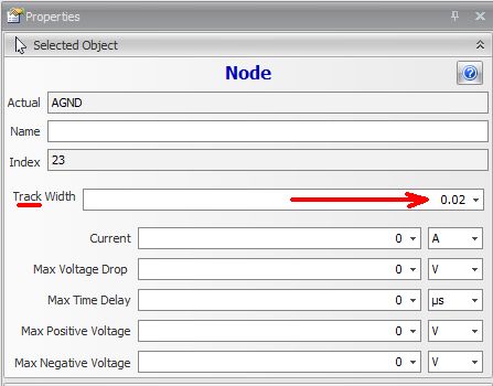
If you want to change the look (Colour or width) in the Schematic in the properties panel (probably collapsed - Use the chevrons to expand it) you will see this section. You can set the Wire width and colour and few other settings. 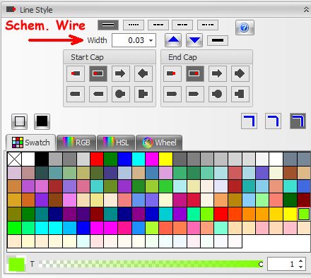
Now, In the PCB work sheet, we have some settings for the PCB only. With the properties panel pinned, click on a section of a track you wish to change its width. Brings up this section n the Properties panel. 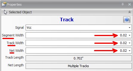
Note there are 3 WIDTHS to play with.. The NET width sets EVERY section of EVERY track on that selected NET. Great for setting a power line's default width.. This is the same as the first selection I mentioned in the SCHEMATIC work sheet. The TRACK width sets EVERY section of the selected track between 2 points (ie. pads, or other tracks) so this could set 4 or 5 segments of track at the same time. The SEGMENT width sets ONLY the selected segment(s) - You can select several SEGMENTS of track by holding down the Crtrl button. So in your case of fattening up nearer the power input, use either TRACK or SEGMENT widths. Hope that helps. Kind Regards, Mick Mick's uMite Stuff can be found >>> HERE (Kindly hosted by Dontronics) <<< |
||||
| bigmik Guru Joined: 20/06/2011 Location: AustraliaPosts: 2981 |
Hi All, I have added a short 1 minute video clip (created by Iliya- Author of AutoTRAX DEX) in the Doc Register. It is listed in the main Doc Register link above but you can direct download it from HERE!!! Please note that I had to ZIP this file up to abide by Gizmo's site rules for the Doc Register file types, so download it and unZIP it to watch.. If you have purchased DEX of course you can do this live by using the project file I have already included in the Register. Kind Regards, Mick Mick's uMite Stuff can be found >>> HERE (Kindly hosted by Dontronics) <<< |
||||
| bigmik Guru Joined: 20/06/2011 Location: AustraliaPosts: 2981 |
Hi All, Iliya, The Bloke who wrote AutoTRAX DEX, has created an ONLINE and ePUB version of the manual I wrote and is hosting them on his site. They can be found HERE!!!! Now we have it in 3 formats, (PDF, ePUB and ONLINE-HTTL).. Now if I got $1 for each copy I will be rich ..... or maybe I could buy a beer!!!
Only kidding, I did it for the love of it I do not want any reward for it at all. Kind Regards, Mick Mick's uMite Stuff can be found >>> HERE (Kindly hosted by Dontronics) <<< |
||||
| paceman Guru Joined: 07/10/2011 Location: AustraliaPosts: 1329 |
Great stuff Mick, and well deserved. You're going to be famous.
Greg |
||||
disco4now Guru Joined: 18/12/2014 Location: AustraliaPosts: 1130 |
Hi Mick, Great guide. Thanks Gerry F4 H7FotSF4xGT |
||||
| bigmik Guru Joined: 20/06/2011 Location: AustraliaPosts: 2981 |
Thanks Greg and Gerry, I don't know about famous but I am happy if it helps someone. I know I wish something like this existed when I first bought DEX. Kind Regards, Mick Mick's uMite Stuff can be found >>> HERE (Kindly hosted by Dontronics) <<< |
||||
| Page 1 of 2 |
|||||
| The Back Shed's forum code is written, and hosted, in Australia. | © JAQ Software 2026 |
