
|
|
Forum Index : Windmills : My unorthodox Build
| Page 1 of 8 |
|||||
| Author | Message | ||||
| BarkyJ Senior Member Joined: 26/04/2018 Location: New ZealandPosts: 114 |
Greetings After asking lots of questions on here, and having some really good input from David (Huge thank you David) and a few others, I thought I would start a build thread for my windmill. I call it unorthodox as its potentially not quite in line with the norm, but hopefully it doesn't stray too far from the well known stuff everyone here is use to. I am an engineer by trade, I did a Mechantronics degree, so am sort of somewhere between mechanical and electronics, without having an extreme stance in either. I was an Automation Engineer for a number of years doing industrial control systems, and in the last 7 years have been back doing electronic design for an Australian company. I am not an expert in windmills, you could call me a noob. I am not an expert in electronics, not am I an expert in mechanical engineering. I like to tinker, I like to try things out, and I like to learn from mistakes. All input/feedback and constructive criticism is welcome, treat me like a sponge. The way I look at life is, just because the majority does it one way, doesn't mean its necessarily the right way - is the way I look at things. A lot of the time, the majority is correct though. So please this is not intended to cause offence to anyone, its just I like to take things on with fresh eyes, make my own evaluations of things, put my spin on things, and potentially fail and learn, try again, and hopefully succeed. Time will tell. So I am going to build a Dual Stator windmill, configured for 1x12C Delta, using 36 pole stators, black cap rotors, and at this stage with a 3m prop diameter, running into a home made controller which controls the output load sort of on a MPPT based dynamic equation (rather than table), and at this stage all power will go into hot water, or into another dump load of some description. To start off with initially, I will be using a 630mm diameter 18mm wall thickness main stormwater PCV pipe (its a monster), to build my blades, and may eventually go to the amazing GOE333 ones in a few months etc, depending how things go. The purpose of this is to learn from. Plus, our hot water is the highest portion of our power bill by far, so chugging away all day with some wind and only boosting it with AC if required, will save me a few bucks for sure. Eventually down the line, I might look at going into a grid tied system, but that is still to be decided. I have no interest going into batteries, at this stage anyway (but likely never). After reading lots on this page, the aim for me is to go tail-less. I am not sure how others feel on this, but the idea I have at this stage is to have a centre pole between the 2 stators, and the turret will be electrically driven with a geared DC motor to point into the wind based on an external wind direction sensor. This then allows me to turn the turret out of the wind by whatever degree amount I determine, or at 90 degrees if I want it to essentially stop. I want to do this for a few reasons. In my current location, the windmill will be fairly near the house, and from what I have seen, quite a bit of noise comes from the windmills furling and fluttering around on their pole. Having it driven 'may' enable quieter operation - however at the same time this might be completely rubbish. The second reason is that while automatic furling is great as it self governs itself, I wanted to do something a little different, and also have greater control if conditions go negative. I will have a wind direction sensor and wind speed sensor close by, and have all the data going into my controller and displays in various ways, and some of it used for control etc. Building the same thing as everyone else, is not my cup of tea. Another reason why I am wanting to do my own controller, is this type of thing is attempted less often by the majority of people playing with windmills. Its just something a little different, and if it works great then I have something a little unique. I have seen pure hardware control solutions, off the shelf solutions both cheap and expensive, but less often have I seen controller based solutions with software determined dynamic MPPT sort of control. Just from what I have seen anyway. I have been designing things in Solidworks CAD, and have some concept images, which I am going to be putting into practice starting this Friday, have taken the day off work and will hopefully get the main chassis fabricated. I have had some bits waterjet cut out of plate, and I have 3D printed some spacers and bits which I will show in my next post, for attaching the stators etc, and Im pretty excited to see how it will all go together on Friday. My design is fairly simple, there is nothing magic going on here, no futuristic designs or anything dramatic like that, this is just the initial concept, which I hope to be functional. More to come. :) |
||||
| BarkyJ Senior Member Joined: 26/04/2018 Location: New ZealandPosts: 114 |
I have modelled the black cap rotor and 36 pole stator in solidworks, then the metal centres which go into the stator, then designed some bearing holder spacers for the centres of the stators, then put them onto a simple chassis. Then figured out the drive shaft using the original older style male ended shaft. Popped out the build in plastic bolts in the black rotor caps, and figured out how far the shafts can insert into the caps, how much sticks out the back, and adjusted the centre chassis to suit the lengths etc. Things are going well. Here are a few pictures. These are at various stages of the last week, so some are newer than others, and I was using the newer female ended shaft at the stage of one of these images. Just what I took screenshots of. 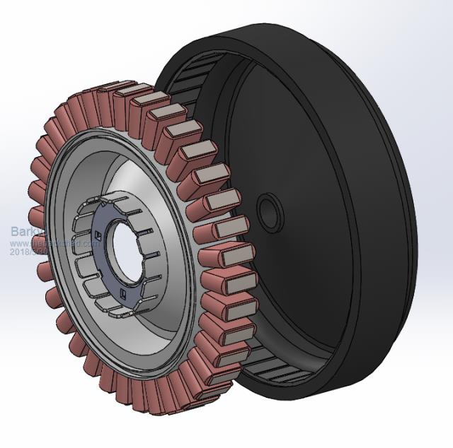 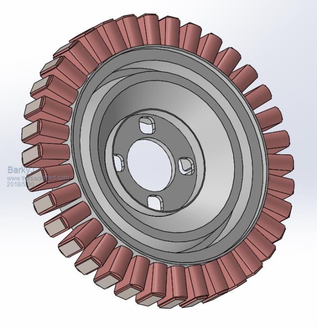 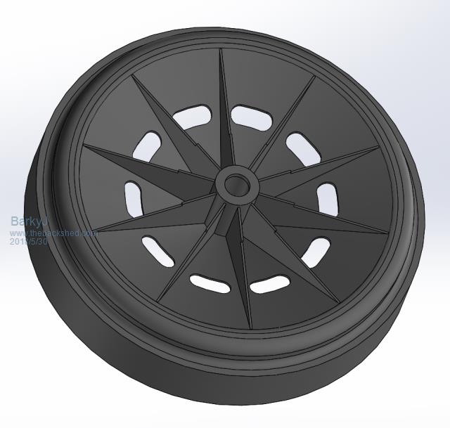 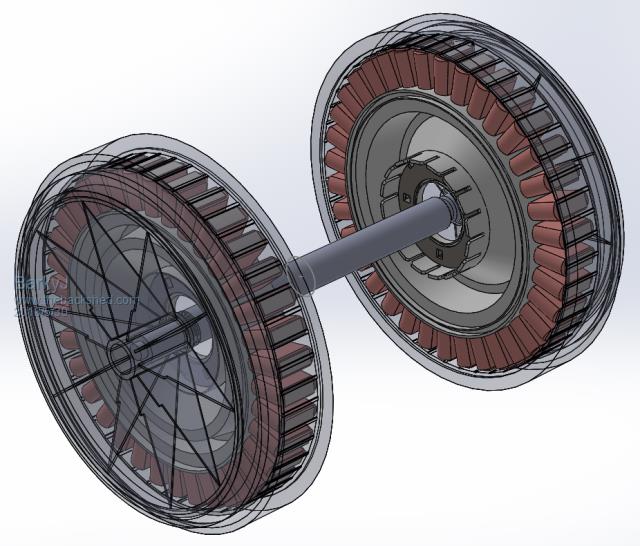 |
||||
| BarkyJ Senior Member Joined: 26/04/2018 Location: New ZealandPosts: 114 |
Here is a bit of an exploded view of the drivetrain and spacers, nothing magical here, but quite neat to see.  |
||||
| BarkyJ Senior Member Joined: 26/04/2018 Location: New ZealandPosts: 114 |
So referring to the exploded view above, after the metal rings which locate into each side of each stator, I designed up 2 mild steel rings. One out of 6mm plate, which would have a standard 6005 bearing pressed into it, so 6mm was in the plate, 6mm sticks out. The portion which sticks out, then goes into the stator in the stock location, and the spacers 4 bolts then line up with the stators 4 bolts. Next is another plate, 100 thick (in the wrong order on the left side of the exploded view, oops), which has a smaller diameter hole so the bearing cannot move, but the centre is free, so this acts as the end stop for the bearing. Sandwiched between the stator bearing lip, and this metal plate. So both 6mm and 10mm plates when stacked together, just come past the 'fingers' on the back of the stator, which use to locate the stator in the washing machines outer drum. So now we have clearance of these fingers, it can be bolted to the central chassis. Same deal on the other side. The shaft worked out great. With the centre plastic bolts removed from the black caps, the male ended shaft with the shorter male threaded end (opposite end to where the threaded nut goes on the shaft), can be pushed all the way into the black rotor, so the end shoulder of the male shaft comes up against the end stop of the rotor. This then gives the race where the bearing sits a perfect location, as if the shaft is not pushed all the way in, only part of the shaft is the right diameter for the inner of the bearing. The left side of the shaft in the above explosion, with the nut, works as usual, and the rotor pushes on all the way up to the nut. A standard lock nut can be put on each end, however the left end is where I am having my prop, so some weird stuff is planned here. More to come later. So I have those spacer rings being water cut, to pick up tomorrow. I actually 3D printed them as a single unit with a shoulder, and the bearings press in perfectly with a tight fit, so I might still use plastic rather than the metal ones, I am not sure yet. I printed them 100% infill, so they are solid as, each one took about 5 hours to print. Ill put up some images of those next. |
||||
| BarkyJ Senior Member Joined: 26/04/2018 Location: New ZealandPosts: 114 |
Ill figure out tomorrow when I get the steel pieces, if I go 1 piece plastic or 2 piece steel. But at least I have both options to work with. Here is a pic without the bearing installed, did the 2nd one in green. |
||||
| Warpspeed Guru Joined: 09/08/2007 Location: AustraliaPosts: 4406 |
There is a lot of very original thinking going on here, and at a very professional level too. Burning with anticipation for what is to come. Cheers, �Tony. |
||||
yahoo2 Guru Joined: 05/04/2011 Location: AustraliaPosts: 1166 |
there are some other bearing options that could make things easier and more robust. Not saying you should use them just making you aware of whats out there. In agriculture we use a thing called a self centering bearing, pressed sheetmetal flanges and a locking ring (tightened against the direction of rotation) they are as tough as old boots because everything is locked solid, no slop at all. 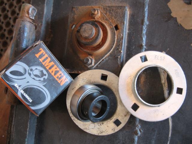 I'm confused, no wait... maybe I'm not... |
||||
| Warpspeed Guru Joined: 09/08/2007 Location: AustraliaPosts: 4406 |
The 6005 bearing is plenty strong enough, as I suspect it only has to support the two F&P rotors. Some of "the weird stuff" to come, probably involves a very cunning and super strong quite independent main turbine support bearing, and a coupling of some kind. Cheers, �Tony. |
||||
| BarkyJ Senior Member Joined: 26/04/2018 Location: New ZealandPosts: 114 |
Thanks Warpspeed - more to come. Thanks Yahoo2 - I started off looking to use the 56205 bearing and F205 carrier that Gizmo used in his public plans, but they just weren't going to work in the configuration I am planning on. Any idea of the part number of the bearing you have there? Always happy to consider other options, thanks for this idea. |
||||
| yahoo2 Guru Joined: 05/04/2011 Location: AustraliaPosts: 1166 |
Here is some examples of a laminated timber GEO-222, the lamination is done to get extra strength using the grain of the timber in the correct direction. https://www.royalwindandsolar.com/wind this is using these blades on a geared head. One of Chris Olson's massive builds. if you get stuck or have problems with the pipe, building with timber is always a good option. 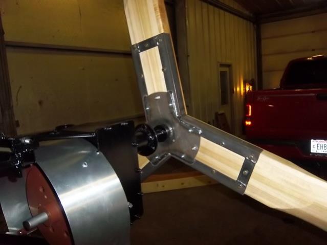 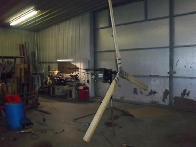 I'm confused, no wait... maybe I'm not... |
||||
| BarkyJ Senior Member Joined: 26/04/2018 Location: New ZealandPosts: 114 |
Very nice |
||||
| BarkyJ Senior Member Joined: 26/04/2018 Location: New ZealandPosts: 114 |
Just wired both stators up for 1X12C Delta, hopefully correctly. Same length wires used on all 3 phases, with the jump over in phase. Measuring resistance between the 3 combinations of connections between phases, and the first stator is 10.36, 10.36 and 10.37 ohms. The second stator is 10.42, 10.43 and 10.44 ohms. Getting everything ready for my day off tomorrow, to get this main chassis proof of concept built. Heading to my Dads place, where he has a small lathe, and old Arc Welder and my Mig welder, however I have a feeling my Mig isnt working at the moment, so likely this will have to be Arc welded up and then cleaned up afterwards. Went to a scrap yard this afternoon and got a bunch of pipe, box, plate offcuts, so we should be all sorted with bits and pieces to try things out. Got some parts back from the Waterjet today, Dad collected those while I was at work, so ill see how those turned out tomorrow also. The rings for the bearing as mentioned, along with the end caps for the main chassis which the stator assemblies bolt into, along with the first stage output disc which goes on the outside of one of the rotors, which will have the blade disc bolted to. If this idea works that is. If not, I have a 2nd idea. More later. |
||||
| yahoo2 Guru Joined: 05/04/2011 Location: AustraliaPosts: 1166 |
No i would have to look it up. i use fafnir bearings so it would probably be a 205 RA-RR or RR series but I dont recall the exact number. I'm confused, no wait... maybe I'm not... |
||||
DaveP68 Senior Member Joined: 25/11/2014 Location: New ZealandPosts: 292 |
Hi James Hope the data that I provided is of use to make the MPPT based dynamic equation do it's job as opposed to the table that I've had some success with. Look forward with anticipation on some real world published data. David There are realities if you do not accept, will lead to frustration because you will be spending time on wrong assumptions and the results cannot follow! The Dunning Kruger Effect :) |
||||
| BarkyJ Senior Member Joined: 26/04/2018 Location: New ZealandPosts: 114 |
Thanks Yahoo2 Thanks David, yes - amazing help and I will get back into the controller stuff later this long weekend. Now that I have THIS.... Here are some progress shots from today: 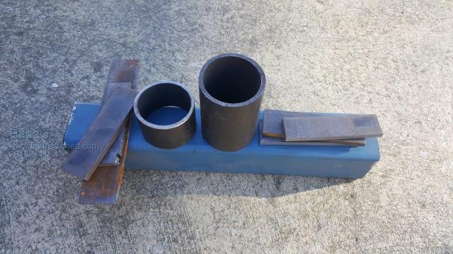 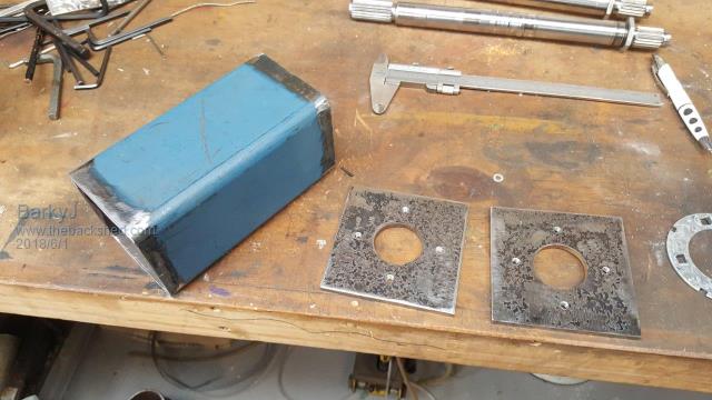 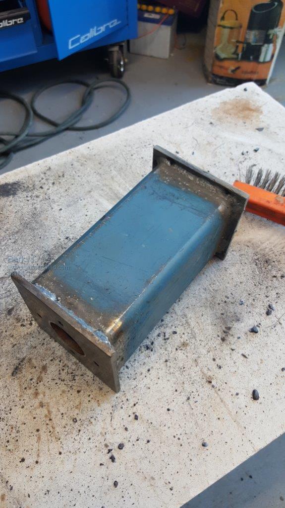 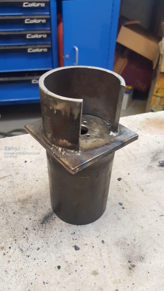 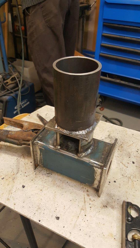 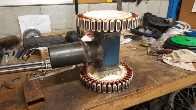 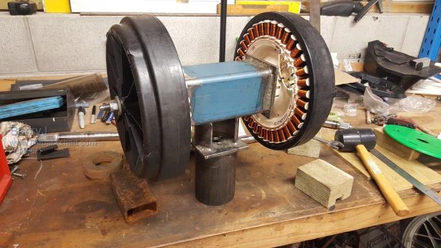 Really happy, its coming together nicely. If you are wondering what the gap in the round tubes is for, this is to access the slip rings (to install it etc), and also where the wires from the stators etc will go to, to then go down the pole via the slip rings. I got a 12 channel 5A per channel stainless slip ring coming, which should be more than enough to cope with the 1x12C Delta currents, which in theory should peak at around 2.8A per stator. Each stator will have its own 3 phases going through the slip rings, so 6 channels, and they will combine down on the ground after the rectifiers. I then have 6 channels for other things, such as RPM sensor, etc. More to come over the weekend. |
||||
| DaveP68 Senior Member Joined: 25/11/2014 Location: New ZealandPosts: 292 |
Yes the 5A rating per channel on the slip ring won't be exceeded as the peak AC output current between phases from a 1x12C Delta stator is 4 Amps. As mentioned before if that current is reached the stators will be in saturation. This of course is unwanted state if reached. When we have enough perimeters to measure we should be able to prevent that saturation from occurring. The 2.8 DC Amps is the optimum operating current for peak output power efficiency. It can be exceeded by 20 % to keep the torque on the shaft at a high value in when encountering strong wind gusts. Saturation occurs at a very predictable value of 40% above the optimum current of 2.8 Amps which just so happens to be 4 Amps. With the above already loaded into your MPPT based dynamic equation should be able to attain both an efficient + wide operating range over most wind conditions with a bit of safety margin built in. Just a question re measuring wind direction and using that to drive a geared DC motor. Is the resolution of external wind direction sensor down to at least 1 deg steps? The reason for asking, is the external wind direction sensor may move very quickly at times. In that case the output will need to be averaged out for the rate of change of the DC motor to drive the spinning blades fast enough on a horizontal axis but not too fast. The blades are like a disc that will resist sudden movement especially at high RPM. Anyway you may have already thought of this... There are realities if you do not accept, will lead to frustration because you will be spending time on wrong assumptions and the results cannot follow! The Dunning Kruger Effect :) |
||||
| Warpspeed Guru Joined: 09/08/2007 Location: AustraliaPosts: 4406 |
Dave, Barky seems to have the whole plan worked out in very great detail. Lets just be patient and watch the whole magnificent thing take shape. Cheers, �Tony. |
||||
| BarkyJ Senior Member Joined: 26/04/2018 Location: New ZealandPosts: 114 |
Hi David Good to get all this backed up as I go along, thanks. So the stator peak is 4A or so, is this at the AC level, or is this the resulting rectified DC current output? Regarding wind direction sensor, its an RS485 wind direction sensor and another RS485 wind speed sensor, so both will feed back into my controller over RS485 coms. I believe they are Modbus protocol, so my controller will just turn that into a direction and speed as fast as is supported. In terms of moving the actual turret, that is still to be determined, but yes for sure it will be averaged out, and I may only change things every x duration. So that is still to be figured out, but it wont be as flighty as a normal tail, is the plan. I might move once every 10 seconds, or something, really dont know yet, we shall see what happens I guess. Hi Warpspeed All comments are welcome, no sucking eggs etc going on here, happy to hear everything and anything. As for the magnificent thing, hah, well we shall see I guess. It might be a complete failure, but hopefully it produces some power and can be improved on as time goes on anyway. Plan is a loose term, but I have a general idea of what I am wanting. The details sort of emerge as each piece goes on. I have just cleaned off my workbench in the garage, which was horrendously cluttered with past project skeletons, shrapnel, and general rubbish. Now to wire up my test rig which I had 2x6C Star, onto this 1x12C Dual Delta. I am excited, and wondering if anything will go pop! My Drill included!! :) |
||||
| BarkyJ Senior Member Joined: 26/04/2018 Location: New ZealandPosts: 114 |
I am pretty stoked with progress though, as the actual thing came out just like my design, which I actually forgot to post here before the other images. Here it the guts of the design: 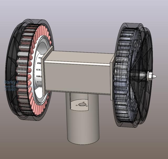 Here it is a few stages along. I have already started printing the cover supports. Last one is in the printer as we speak. I will either cover it all (with clearance to the rotors) with 0.5mm Aluminium sheet, or I might use that 0.8mm thick clear polycarbonate UV safe sheet you can buy in a roll from Bunnings. Not sure yet. But something along those lines, to keep most of the weather out of the guts. 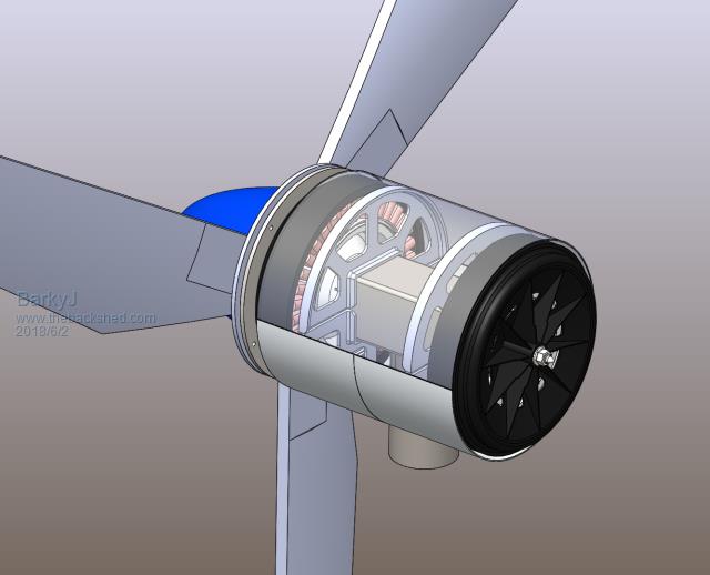 The blades pictured are extremely first pass CAD concepts only, I haven't done much research on these yet. At the moment they are just placeholders Here is one of the cover supports still on the printer glass bed. Fits snug over the square box section, and will be fastened in place, and then the covers wrapped over the top in some fashion. All still to be determined yet. 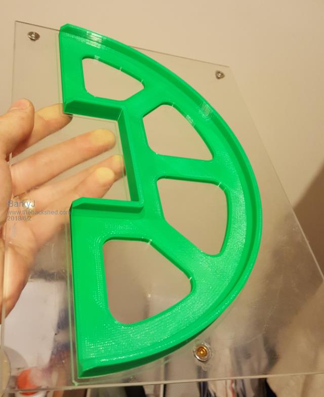 |
||||
| brucedownunder2 Guru Joined: 14/09/2005 Location: AustraliaPosts: 1548 |
Very nice project there, Barkly. I'm a bit old , so I have to ask . That green frame thingo ?. you say it's on the printer glass bed or something ,,what do you mean by that and how is it actually made -there, told ya I was a bit dumb?!!. luv your drawing on that computer , wish I had listened to my teacher at school way back then, might be a rocket scientist by now,Eh?. You are doing just great ,along with that Mark fella doing the inverter , youse guys are smart. Have a nice weekend,don,t forget the aerogard . Bruce Bushboy |
||||
| Page 1 of 8 |
|||||
| The Back Shed's forum code is written, and hosted, in Australia. | © JAQ Software 2026 |
