| |
Page 1 of 7   |
| Author |
Message |
flc1
Senior Member

Joined: 20/11/2011
Location: New ZealandPosts: 242 |
| Posted: 07:40pm 25 Jun 2017 |
 Copy link to clipboard Copy link to clipboard |
 Print this post |
|
The windturbine has three x 36 pole copper f n p stators,with black caps.
One stator is half cut( 2x 6c) and wired in delta and fitted with a capacitor doubler, the second stator is a third cut(3x4c) wired as star with no cap doubler and the third stator is 6th cut(6x2c),wired as delta and is also fitted with a cap doubler.
The stators are Direct drive, and have a rear disc brake from a motorbike fitted to the drive shaft which is activated by a voltage switch,which ativates a 12 volt dc actuator to apply the disc brake to stop the turbine when it goes over 88volt dc.Also have furling on the tail,I am going to add another 12volt actuator to the tail aswell and that will work off the same voltage switch as the disc brake,to furl the tail at the same time when the brake starts, it will be able to furl without the actuator in high winds if all the electronics fail. I think with all that we have read about the GOE222 blades,and having 5 of them the brake and auto furling will definitely be needed.
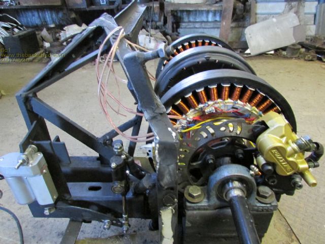
disc Brake.
The gridtie inverters are the same 45-90 volt dc mppt model that I used on my other turbine, 2x 1000w models.
While searching online I found a gridtie inverter that has a wide working voltage of about 30-540v dc, which I think would suit the f n p stator, If I used that inverter I would not have to cut the stators as much, and would get about 3kw from my tripple stator setup. It would cost about $1700nzd for a 3kw model, so it will have to wait untill I can afford it,I have added extra insulation to the wireing connections etc to handle the higher voltage that this inverter uses, they are nz,au certified aswell,
I told Davep68 about this inverter and he then put a link to it on the back shed with the page named "Wind gridtie inverter 30-540VDC input"
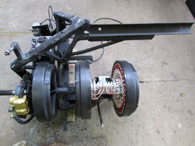
top veiw.
It will have a blade diameter of 3 meters, useing 5 x GOE222 blades that we got from phill, I am currently in the slow process of fitting the blades to the hub.
It will be useing the same tail and body from my old turbine, just lengthened the tail a bit and had to make the turbine cover larger to fit the extra stator. Its an ugly turbine lol.
Hopfully it should put out about 2.2 kw with the cheaper 45-90v inverters and Davep68's cap doublers, and thanks to Davep68 for the voltage switch, which he is currently testing at his place at the moment, and for wireing up the 6th cut stator.
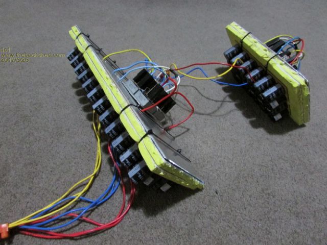
Daves capacitor doublers fitted with rectifiers.
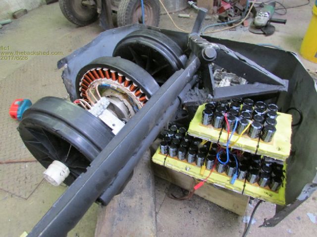
mounting cap doublers
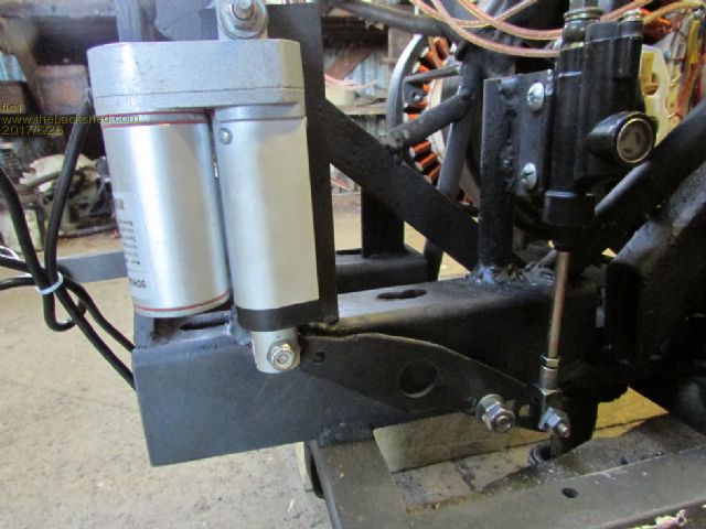
Actuator and disc brake setup.
So hopefully in a week or two the ugly beast should be up n running, fingers crossed.
Edited by flc1 2017-06-27 |
| |
flc1
Senior Member
Joined: 20/11/2011
Location: New ZealandPosts: 242 |
| Posted: 10:09pm 25 Jun 2017 |
Copy link to clipboard |
Print this post |
|
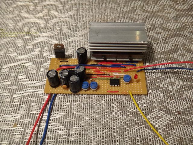
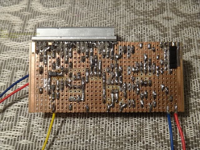
Pics of Daves voltage switch/timer for the brake and furling actuators.
When the switch operates it has a timer that will hold the brake on and furl for a pre set time of about 30mins or anything up to 2 hours. Reverse polarity operated actuators.
There is also a manual switch that operates the actuators if I want to stop the turbine for whatever reason.
The brake actuator takes about 5 seconds to apply the brake,,and I have set it so its not applying too much braking power,don't want any more sheared keyways on the blade hub, and the tail actuator takes about 15-20 seconds to get to about 75% furl, so hopefully by the time the brake disc is starting to heat up ,the turbine will be furled and stopped.
I have kept the same one way dampner on the tail that was on the old turbine, to stop the tail smashing back into its seat in storms,and snapping off.
I have also added a vent in the turbine housing and ducting to the disc,to help keep things cool.
This turbine is made from aircraft , washing machine, tractor, car and motorbike parts,and some other parts of unknown origin so its a true mongrel.
Edited by flc1 2017-06-27 |
| |
flc1
Senior Member
Joined: 20/11/2011
Location: New ZealandPosts: 242 |
| Posted: 01:02am 26 Jun 2017 |
Copy link to clipboard |
Print this post |
|
And as I did with my last turbine, it will be painted Black.
Blacks a good color for hideing mistakes and birdsh*t welding.Edited by flc1 2017-06-27 |
| |
kitestrings
Senior Member
Joined: 23/04/2014
Location: United StatesPosts: 102 |
| Posted: 05:43am 26 Jun 2017 |
Copy link to clipboard |
Print this post |
|
Nice looking build flc1! I especially like your creative reuse of parts from other things. Look forward to seeing it up.
A couple of questions/comments, when you have time:
What made you decide to go to 5-blades?
Are the caps solder in, or are they plug in terminals? I just wondered about testing/replacement down the road.
You might consider having the furling actuator operate ahead of the brake. The furling will take a big chunk of power away from the thing, with a delay the brake will have a much more manageable job.
Best, ~ks
|
| |
flc1
Senior Member
Joined: 20/11/2011
Location: New ZealandPosts: 242 |
| Posted: 04:01pm 26 Jun 2017 |
Copy link to clipboard |
Print this post |
|
Gday KS, thanks for that, my idea of the 5 blades was just to get more torque to start the 3 stators in low winds and allso more shaft power for later when changing to high voltage inverter, and Im hopeing that the extra blades will create more drag at peak rpm so as to help keep peak rpm under controll.I think my tail may be abit too heavy so it may furl late,electronics fail,,,,blades screaming...flying to bits etc,
My tail weight was fine with the old set of blades,but if what we read about these new blades is correct ,then over speed may be an issue.
but,,, with the increase in diameter I was thinking it may furl in a lower windspeed than before ? ie more pressure from lager swept area, HA....which one is it?
just have to wait n see what happens ,
The caps are soldered in, Daves theroy was with the larger number was that if 1 or 2 fail ,it should not have a large effect on performance.Bit more of a mission to change them though.
Im hopeing to do away with the cap doubler when I upgrade the inverter to the higher voltage model.
I agree with what you say about the furling, maybe we could put a seperate circut to the brake actuator which has a 10 second delay? or it will have to be a whole seperate timer board,you reading this Dave...what do you think?Edited by flc1 2017-06-28 |
| |
DaveP68

Senior Member
Joined: 25/11/2014
Location: New ZealandPosts: 292 |
| Posted: 08:59pm 26 Jun 2017 |
Copy link to clipboard |
Print this post |
|
Hi Fred
I think the brake should be a last resort option and triggered separately. This can still be done from the same timer circuit as it could simply be turned on by a relay on a slave feed that is controlling the furling system. Very easy to add into the current setup.
What do you think?
David
There are realities if you do not accept, will lead to frustration because you will be spending time on wrong assumptions and the results cannot follow! The Dunning Kruger Effect :) |
| |
flc1
Senior Member
Joined: 20/11/2011
Location: New ZealandPosts: 242 |
| Posted: 10:03pm 26 Jun 2017 |
Copy link to clipboard |
Print this post |
|
Thanks Dave,that sounds like the right idea, the brake needs to work in with the furling,and stop the blades, furling will not stop the blades unless you get the furl angle exact,so that the blade angle of attack is 0 or mayb slightly negative angle and even then the blades can still turn abit with side guts etc.
Thanks to Trev from" live by nature and drive by nature" for the dual bearing hub for 2 of f n p stators and for the daul f n p shaft to go with it, made life alot easier. |
| |
brucedownunder2
Guru

Joined: 14/09/2005
Location: AustraliaPosts: 1548 |
| Posted: 09:12pm 28 Jun 2017 |
Copy link to clipboard |
Print this post |
|
Nice work, Flc.
takes me back a few years,,, used to have a bicycle disc brake and manual caliper ,but she blew up on me -nice try ,but???.
had a ribbed belt drive , I think it came off the timing pulleys it was supposed to drive the dual neo type fand P -never mind .
I'd like one day to copy your idea(have the gear) , .o
One question --what does your complete set-up weigh?
Nice work
Bruce
Bushboy |
| |
flc1
Senior Member
Joined: 20/11/2011
Location: New ZealandPosts: 242 |
| Posted: 10:57pm 28 Jun 2017 |
Copy link to clipboard |
Print this post |
|
Gday Bruce, thanks
I had ideas of useing hydralic bicycle brake with a 3 blade set up dual stator, but I think it would not be up to the task with a 3 meter diameter.The motorcycle disc is chunky and designed to stop a heavy weight so should be good.
Don't copy it just yet, have to see if it all works first ha!
I think the big ugly thing would probably be between 30-45kg with the hub n blades,, I have not weighed it.But there is a set of scales in the shed.
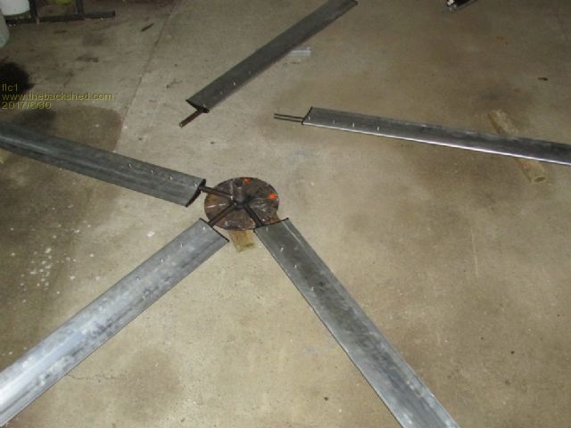
The frame you see in the pics was made originally for 2 stators side by side and gearing,
Looking back now I probably should not have used this frame and should have built a completly new one, it would have been slimmer and lighter and easier to make a cover to fit. but never mind, it is what it is.
Still picking away at the hub n blades at the mo, hour here and ahalf n hour there, after work etc, the tail actuator has been odered, and I think that will be the last part that is needed to finnish it.
Do you have any pics from your pully setup with the f n p? Would be good to see.
Fred |
| |
brucedownunder2
Guru
Joined: 14/09/2005
Location: AustraliaPosts: 1548 |
| Posted: 12:48am 29 Jun 2017 |
Copy link to clipboard |
Print this post |
|
Yes, have a few photos of the disc brake set up .
Probably back a few years ,go to brucedownunder2 ,,search,,,disc brake set up ,,,,and around that area you should see a few pics,,
I,ll get around to posting them in a day or so ,,,been along time since I,Ve posted pics ,so bare with me , or someone more smarter than me could drag them out and attach them to your post if you don,t mind .
Bruce
Bushboy |
| |
flc1
Senior Member
Joined: 20/11/2011
Location: New ZealandPosts: 242 |
| Posted: 12:53am 29 Jun 2017 |
Copy link to clipboard |
Print this post |
|
The tail actuator was $65nzd out of china,through the aliexpress web site.
To buy the exact same actuator here in nz,same model from the same company etc $80-150nzd. |
| |
flc1
Senior Member
Joined: 20/11/2011
Location: New ZealandPosts: 242 |
| Posted: 01:03am 29 Jun 2017 |
Copy link to clipboard |
Print this post |
|
Yep found it Bruce, thats a nice tidy setup in the pic, how long did it last? |
| |
brucedownunder2
Guru
Joined: 14/09/2005
Location: AustraliaPosts: 1548 |
| Posted: 10:59am 29 Jun 2017 |
Copy link to clipboard |
Print this post |
|
Ok,
I,Ve got the same hydraulic motorbike disc and caliber with the master cylinder waiting for this lazy ol codger to get going again..
I haven,t seen the black rotors yet,may have to do some scrounging like the old days,lol.
What type or any telltales on the washing machines to look for Without me having to pull the bum off the machines.
I,Ve got Trev,s housing,will have to mod a shaft or invent a new type.
Did anyone find out if any car splined connectors fit the f and p spline
I had a long look many years ago and thought a Toyota Corolla tail shaft was fairly close ,but I think f and p have machined their own precise spline size,, phill would know,bet he,s watching,hi phill.
Thanks for re vitalising the f and p. Topic . She,s a goog all round diy starter for us guys,and fairly cheap and plenty full source of basic parts.
Hope I,m not busting into your thread too much
Bruce
Bushboy |
| |
flc1
Senior Member
Joined: 20/11/2011
Location: New ZealandPosts: 242 |
| Posted: 03:56pm 29 Jun 2017 |
Copy link to clipboard |
Print this post |
|
Yea Bruce ,go to the dump Ha!
Thats where I get most of mine, and they have no cover on the bottom so just have a look underneath, black rotors are harder to get off,you almost need 3 hands to get it off, easy if sombody is with you to undo the bolt as you pull the rotor.
Leave the stator that the black cap comes off,, it will probably have aluminium wire on it, look for the white rotor cap with the 5 knobs around the outside edge,thats an arrowhead cap, and it will be on a copper 36 pole stator.
I used a female f n p shaft to thread onto the double f n p shaft that Trev sent me, first I drilled out the female shaft end just deep enough to allow the two shafts milled faces to meet, one face at the beginning of the threaded hole and the other at the base of the male thread on the other shaft, so the
two shafts come together firm ,with no sideways movement when tightened.
But the two shafts will undo under brakeing deceleration ,so I cut a small peice out of the side of the female spline so you can see the last half inch long peice of male thread inside the female spline,so the hole is cut about 15 mm in from the end of the spline,,, and weld that thread to the female shaft, ,so once the rotors are on the shaft they are there permanatly,you can slide the rotors along the shaft out of the road of stators etc because Trev has put a spline along most of the male shaft,and bearing housings can be removed from opposite ends of the shafts when joined,just don't weld the shaft untill you have completed everything else,incase you make a mistake with design or whatever and need to remove the rotors or seperate the shafts.Other stuff you will work out as you go,just don't weld the shafts untill you have finnished everything else,,
I think it would be better if you could make a spline that slides tight over the connection of the two shafts,so you don't have to weld them, and held in place with a grub screw.I think Trev might have the cutting bits to make one? Could ask him? But you then have to drill out part of the spline on one of the rotor caps,
I found its just easier to weld them
Edited by flc1 2017-07-01 |
| |
flc1
Senior Member
Joined: 20/11/2011
Location: New ZealandPosts: 242 |
| Posted: 01:34am 30 Jun 2017 |
Copy link to clipboard |
Print this post |
|
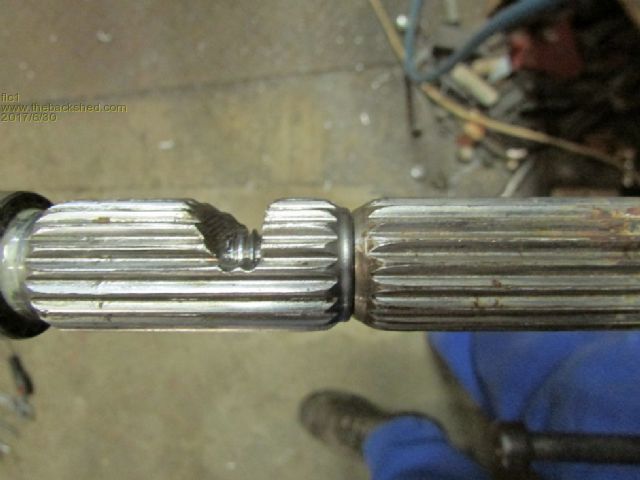
joining the two shafts |
| |
flc1
Senior Member
Joined: 20/11/2011
Location: New ZealandPosts: 242 |
| Posted: 01:49am 30 Jun 2017 |
Copy link to clipboard |
Print this post |
|
deciding if I should use 4 or 5 blades, after descussions with Dave, may go with 4 |
| |
DaveP68
Senior Member
Joined: 25/11/2014
Location: New ZealandPosts: 292 |
| Posted: 09:59pm 01 Jul 2017 |
Copy link to clipboard |
Print this post |
|
Hey Fred, look forward to the results you get from this new improved F&P wind turbine. Your inspiring me to get my a into g and put my blade to use too.
There are realities if you do not accept, will lead to frustration because you will be spending time on wrong assumptions and the results cannot follow! The Dunning Kruger Effect :) |
| |
flc1
Senior Member
Joined: 20/11/2011
Location: New ZealandPosts: 242 |
| Posted: 12:58am 02 Jul 2017 |
Copy link to clipboard |
Print this post |
|
will leave the brake on manual operation with the switch ,but have the auto furling, going to change all 3 stators to 3 uncut stators rewired to delta,same black caps, and going to go with high voltage inverter, no cap doublers, no 45-90 volt inverters, they are being sold to help finnance high voltage inverter. yea Dave go hard and build a turbine, I know where you can get some inverters lol. |
| |
flc1
Senior Member
Joined: 20/11/2011
Location: New ZealandPosts: 242 |
| Posted: 02:23am 02 Jul 2017 |
Copy link to clipboard |
Print this post |
|
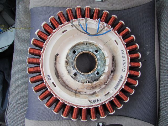
uncut 36 pole ,rewired as delta |
| |
flc1
Senior Member
Joined: 20/11/2011
Location: New ZealandPosts: 242 |
| Posted: 03:45pm 03 Jul 2017 |
Copy link to clipboard |
Print this post |
|
Does anybody have any rpm and wind speed data for these type of blade with a set of 3 or more, at or near 3 meter diameter?Edited by flc1 2017-07-05 |
| |
| |
Page 1 of 7 |
