Notice. New forum software under development. It's going to miss a few functions and look a bit ugly for a while, but I'm working on it full time now as the old forum was too unstable. Couple days, all good. If you notice any issues, please contact me.
tinyt Guru Joined: 12/11/2017 Location: United StatesPosts: 561
Posted: 04:53pm 12 Apr 2026
Copy link to clipboard
Print this post
Efficiency = 100 X (2372.3 / 2379.2) = 99.7% WOW!!
This is an inverter manufacturer's and DIY'ers dream!!
Bryan1 Guru Joined: 22/02/2006 Location: AustraliaPosts: 2176
Posted: 09:57pm 12 Apr 2026
Copy link to clipboard
Print this post
With Phill's suggest of switching noise causing a higher amperage moving the clamp meter to close to the Vbat ground was the best move so a true reading could be taken.
Once again a huge Thank You to all the members that have helped me with this project and I am just glad it's finished and working.
Regards Bryan
Bryan1 Guru Joined: 22/02/2006 Location: AustraliaPosts: 2176
Posted: 11:23pm 12 Apr 2026
Copy link to clipboard
Print this post
Thought to take a measurement with just the shed load going.
VBat 28.7 VBat current 34.2 Energy meter Watts 101 average
So 100 x (981.5/101) = 97.1%
Just got a text that Ali inverter is here too
Bryan1 Guru Joined: 22/02/2006 Location: AustraliaPosts: 2176
Posted: 12:02am 13 Apr 2026
Copy link to clipboard
Print this post
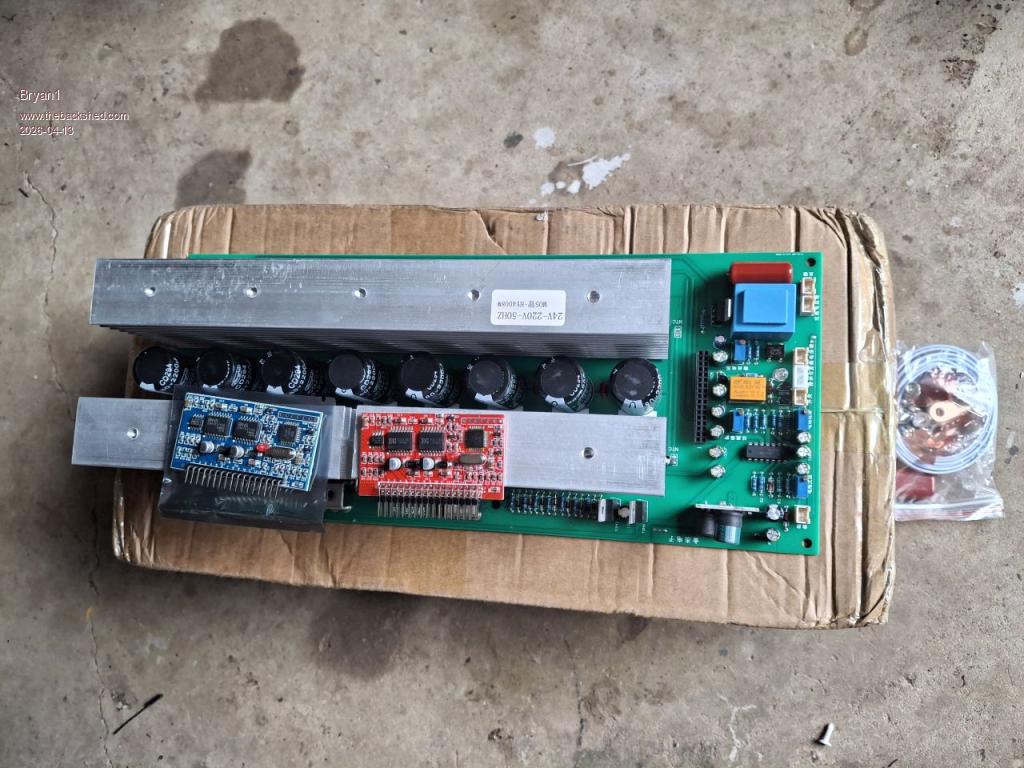
Ok this Ali board is here
On the left is the blue one I'm going to use as it is the upgraded board.
Now as all the outputs are in Chinese could a member please tell me what each connection is as we do need to know what each one is.
Regards Bryan
Bryan1 Guru Joined: 22/02/2006 Location: AustraliaPosts: 2176
Posted: 12:39am 13 Apr 2026
Copy link to clipboard
Print this post
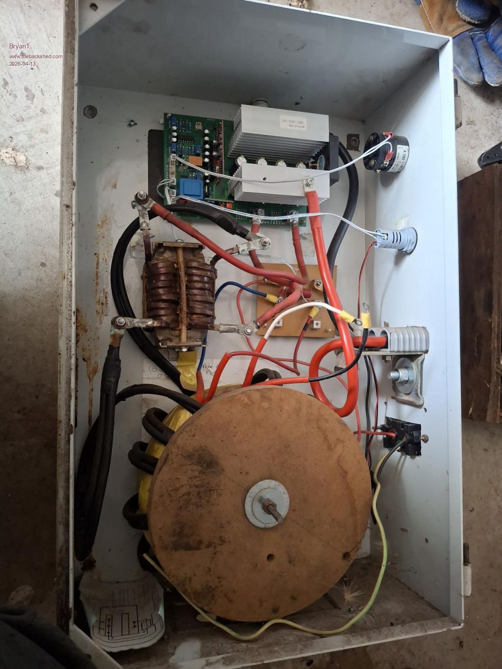
Now I do have that first small inverter to use for this inverter for testing
The choke uses the big choke from the AeroSharp Grid Tie with 10 turns of 6.5x3.5 enameled wire then varnished in. It would be good to set this choke with a scope to see what it can make as dual choke.
I got this design off Tony many years ago now when I tested this inverter it did run both vacuums
There is no pre start setup for this small inverter and it didn't blowup but now I know more a pre start setup will be done.
Godoh Guru Joined: 26/09/2020 Location: AustraliaPosts: 682
Posted: 01:46am 13 Apr 2026
Copy link to clipboard
Print this post
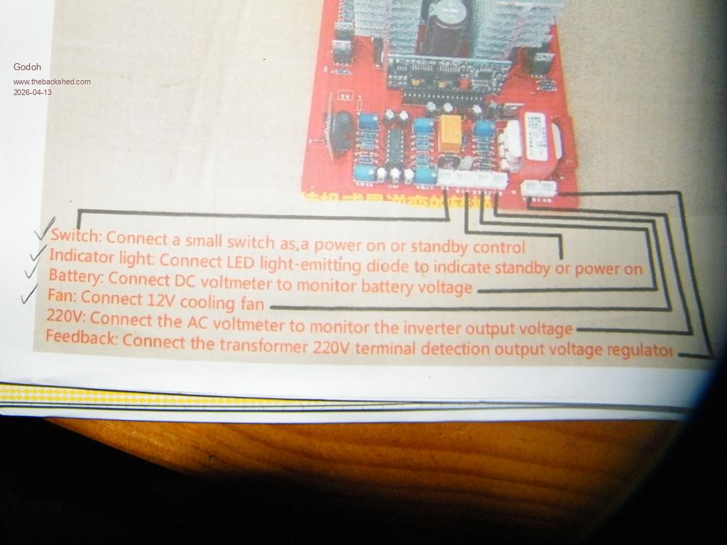
Hi Bryan, the connections can take a while to work out. Near the transformer one of the sockets is for feedback, so if you have a look at which socket goes straight to the transformer that should be the feedback one. Another one is for the LED to show the inverters state, either On or Standby.
The next set of sockets to the left will have one for the fan.
I will take some photos of my board and see if it is the same as yours. Unfortunately they are a few different boards with different arrangements for the sockets. If you can contact the seller of the board they can usually supply a diagram to show how the connections are made.
I will post a picture of my inverter later
Pete
Bryan1 Guru Joined: 22/02/2006 Location: AustraliaPosts: 2176
Posted: 02:33am 13 Apr 2026
Copy link to clipboard
Print this post
Hi Pete I may of answered most of my questions myself as I do have the picture from that small inverter board
Now it shows the top connection at the top of the group is for the fan output, now on this larger inverter at the back of this board is a 12 volt connector. I do assume this would be to connect a fan to the heatsink so I'm wondering if this larger board does have a 2 fan setup.
Also below the 2 trim pots is a 2 pin connector that goes to that vertical board so wouldn't this be a 12 or 15 volt DC input.
Godoh Guru Joined: 26/09/2020 Location: AustraliaPosts: 682
Posted: 04:07am 13 Apr 2026
Copy link to clipboard
Print this post
Hi Bryan I see on the larger board that there is an extra connector near the small board on the opposite side of the transformer on the board. One way to translate the symbols may be to take photos and use a translation program to translate from chinese to english. None of my boards have that small vertical board Pete
Godoh Guru Joined: 26/09/2020 Location: AustraliaPosts: 682
Posted: 08:19am 13 Apr 2026
Copy link to clipboard
Print this post
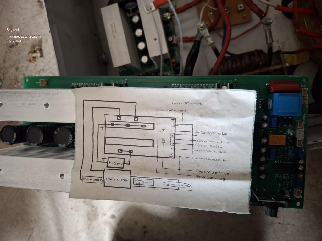
Hi Bryan this is the connection diagram for the board I have
Pete
tinyt Guru Joined: 12/11/2017 Location: United StatesPosts: 561
Posted: 12:35pm 13 Apr 2026
Copy link to clipboard
Print this post
Efficiency = 100 x (Watts Output / Watts Input) = 100 x (Energy meter reading / (Vbat x Bat Current) Efficiency = 100 x (101/(28.7 * 34.2)) = 100 x (101/981.54) = 10.29% ???
Bryan1 Guru Joined: 22/02/2006 Location: AustraliaPosts: 2176
Posted: 03:25am 30 May 2026
Copy link to clipboard
Print this post
Well decided to give my chainsaws a good clean so when I decided to turn on my air compressor thought I have a look at the surge current on the energy meter.
20Kw was the draw and the inverter just handled it now it's just clicked over 82Kwh and still going strong.
Regards Bryan
phil99 Guru Joined: 11/02/2018 Location: AustraliaPosts: 3327
Posted: 04:27am 30 May 2026
Copy link to clipboard
Print this post
Perhaps your energy meter is unable to correct for power factor during a surge. 20kVA looks about right for a compressor motor starting, but it's P.F. during starting is probably around 0.3 so that would be 20 x .3 = 6kW. Still quite respectable.