
|
|
Forum Index : Electronics : Another Inverter Build
| Page 1 of 14 |
|||||
| Author | Message | ||||
Revlac Guru Joined: 31/12/2016 Location: AustraliaPosts: 1281 |
Moved on from the previous egs002 Inverter build, nothing wrong with them but after replacing the SMD driver chips a few times, it soon made sense to me to go and do the Ozinverter, the plug in chips is just a little bit more practical in the early stages of testing, and in the case of repairs. OK Some progress so far. Soldered the 8010 chip on to the SMD carrier, To me it looks quite good. I used this solder flux pen (kester flux pen #951) thought it was worth a try as it was cheaper than some others at the time, works good and plenty left for other jobs, more-so if the bloody lid was tight before it was posted. https://www.ebay.com.au/p/10ml-951-cleaning-Soldering-Welding-Solder-Flux-Pen-for-Solar-Cell-Fpc-PCB/858730345?iid=28247 2451748 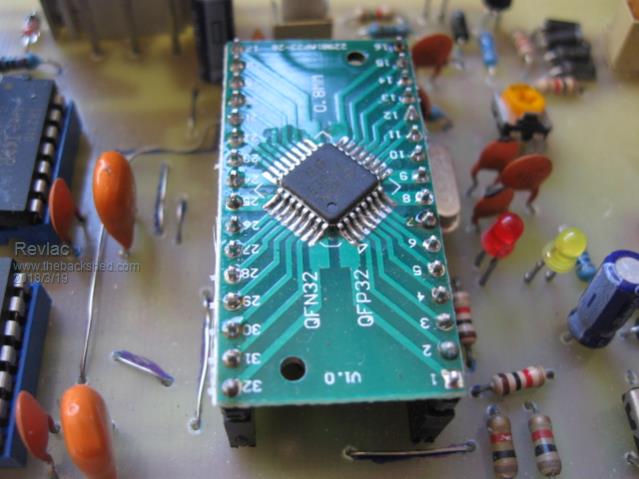 I printed and acid etched The control board, not proud of it either, the copper is thin and pitted to buggery, my fault should have bought some better quality copper clad pcb, anyway I fixed up all the copper tracks and so far its tested and working. 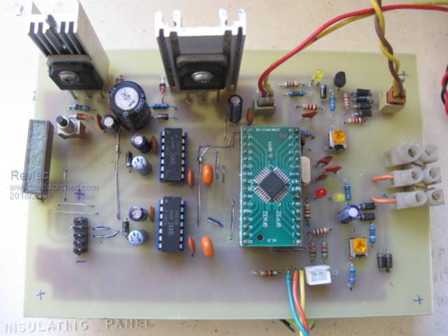 Started on the power board and its still thin copper so after my previous stuff up (crappy laser printer I have) the next idea was to try and just cut around the tracks, looked like an easy way to do it, Haha well it was a bugger to start with using a hand held dremel, It was a better approach to plug in the flexible drive and a small round diamond tip bit, use it like a drawing with a pencil. It doesn't look very neat but I had to try and will see if it works. will probably end up getting the boards made properly in future. 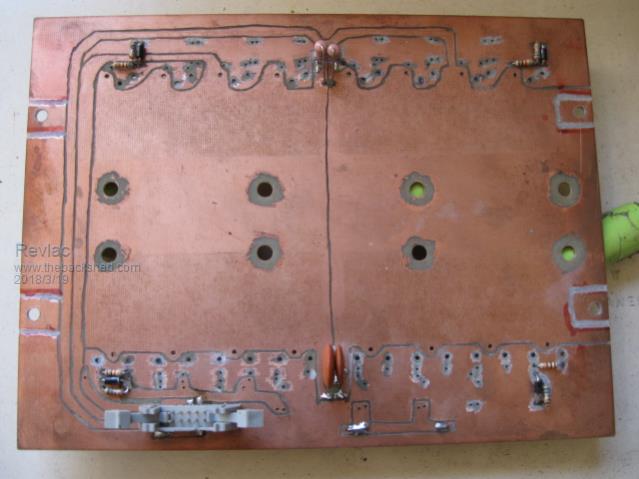 I think I should also run extra copper (wire or strap) between the fet legs an the caps? And same on the top? 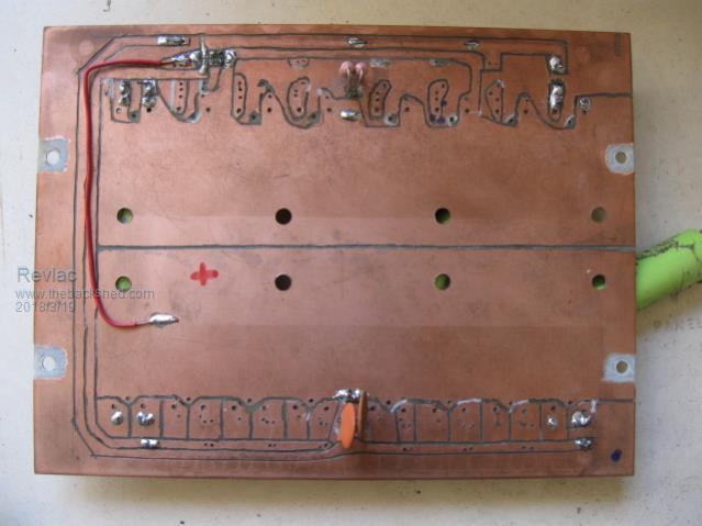 The red positive wire is just to try the thing, the power will be on the heat sinks later. 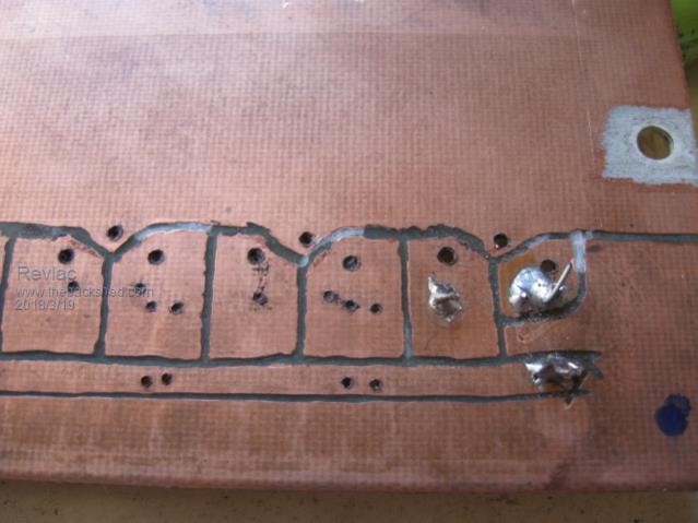 Just wonder if I should knock off the excess copper on the gate drive on the under side of the board or just leave it there? I was buggered for a bit with some sort of eye infection among other things. Now I can see the computer screen again there is a lot to catch up on, Lots of interesting things going on and some nice builds too.  Cheers Aaron Cheers Aaron Off The Grid |
||||
Madness Guru Joined: 08/10/2011 Location: AustraliaPosts: 2498 |
Not the prettiest PCB but should still do the job, if you have some thin copper sheet you could cut that and lay it over the top where the high current is needed. You can't beat the Chinese boards especially plate through which is near impossible to do at home. This a close up of my power board with 2oz copper made by PCBway.com 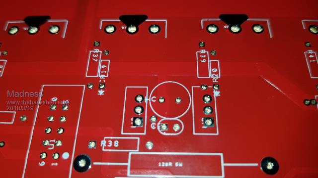 There are only 10 types of people in the world: those who understand binary, and those who don't. |
||||
| Tinker Guru Joined: 07/11/2007 Location: AustraliaPosts: 1904 |
Mad, some areas on your PCB appear to be black, what is that? I'm just curious. Klaus |
||||
| Madness Guru Joined: 08/10/2011 Location: AustraliaPosts: 2498 |
Just a dark reflection on the tinned pads. There are only 10 types of people in the world: those who understand binary, and those who don't. |
||||
| Tinker Guru Joined: 07/11/2007 Location: AustraliaPosts: 1904 |
Ah so des ka. another question, did you use the default clearance around the PCB pads? I increased this, it makes solder blob shorts less likely Klaus |
||||
| Revlac Guru Joined: 31/12/2016 Location: AustraliaPosts: 1281 |
Madness they certainly are neat and tidy looking boards and I will probably go in that direction later. It will put an end to to the DIY boards though, apart from testing designs first I guess. last time I checked, PCBway and others will do minimum 5 boards, perhaps i build 1 using 100mm boards? I know 2 friends around here that would like to go off grid, As yet I havn't convinced them to start a build, if I built something for them I'm certain that i would be stuck with any and all problems they may have, and they have no interest in electronics. Also likely i will build more than 1 inverter for myself. I will have a look around and see if there is some copper sheet around here somewhere. Here is another idea perhaps a silly one, or maybe not, I did play around with electroplating some time ago using some copper sulfate, copper wire a carbon rod from a battery and a 20w solar panel, ended up making the copper wire thicker and the rest i think it was dilute sulfuric acid, well it smelt like it anyway. Cheers Aaron Cheers Aaron Off The Grid |
||||
| Revlac Guru Joined: 31/12/2016 Location: AustraliaPosts: 1281 |
This is with the heat sinks almost fitted up. 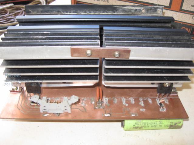 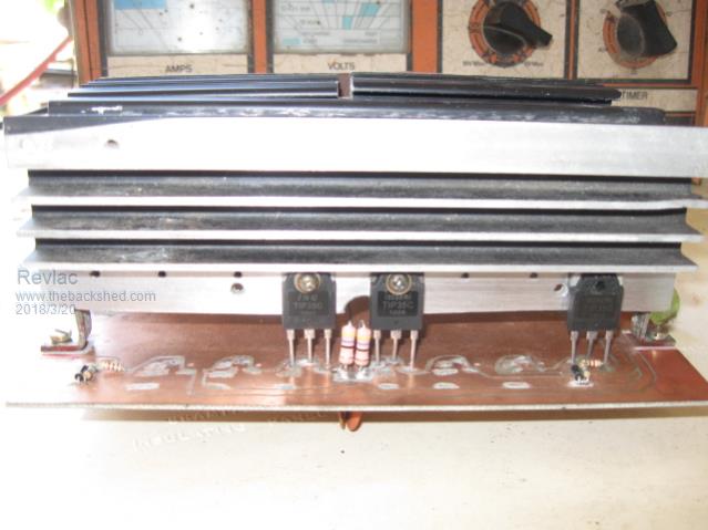 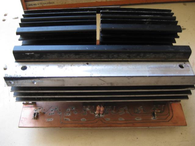 Now I look at It they may be a little small. Cheers Aaron Cheers Aaron Off The Grid |
||||
| Madness Guru Joined: 08/10/2011 Location: AustraliaPosts: 2498 |
No Klaus, I find I don't need to increase clearance, especially with a solder mask. There are only 10 types of people in the world: those who understand binary, and those who don't. |
||||
| Madness Guru Joined: 08/10/2011 Location: AustraliaPosts: 2498 |
Aaron I plan to get a few extra boards soon but that is with the Totem pole drivers if you want to chip in, 5 2 OZ boards gets into above the 2KG limit for China post which 200 X 300 MM. When you work out pricing there are not so good exchange rates and transaction fees that bump up the prices a bit also. There are only 10 types of people in the world: those who understand binary, and those who don't. |
||||
| Madness Guru Joined: 08/10/2011 Location: AustraliaPosts: 2498 |
Sorry I have no idea what this means "Ah so des ka." There are only 10 types of people in the world: those who understand binary, and those who don't. |
||||
renewableMark Guru Joined: 09/12/2017 Location: AustraliaPosts: 1679 |
He means "ah so that's how it is" Mad what's the price on the boards? I need another set for my second build,might be interesting to compare different boards. Cheers Caveman Mark Off grid eastern Melb |
||||
| Tinker Guru Joined: 07/11/2007 Location: AustraliaPosts: 1904 |
its a remnant of learning Japanese 45 years ago  Mark got it right. Mark got it right.Klaus |
||||
| johnmc Senior Member Joined: 21/01/2011 Location: AustraliaPosts: 283 |
Good Day All Madness I would like to buy some of your boards with totem pole drivers if you do order more boards . cheers john johnmc |
||||
| Madness Guru Joined: 08/10/2011 Location: AustraliaPosts: 2498 |
Hi John, It would depend on the total numbers ordered the more ordered the cheaper each PCB is, exchange rates change daily also. 5 ordered around $50 AUD each 10 ordered around $40 AUD each 15 ordered around $30 AUD each 20 ordered around $25 AUD each You can go to www.pcbway.com and check the numbers the boards are 200 X 300 MM 1.6 thick 2 oz copper. Prices above include freight to me from china, there would be local postage as well. I used 65 cents as the exchange rate because when you pay with paypal you don't get a very good exchange rate. Control boards are around $10 - $15 each, I need to redo the design to include the latest update. I would have to start from scratch in the software I use so would take a week or 2 to do that. There are only 10 types of people in the world: those who understand binary, and those who don't. |
||||
| renewableMark Guru Joined: 09/12/2017 Location: AustraliaPosts: 1679 |
Thanks Mad, put me down for two sets. Cheers Cheers Caveman Mark Off grid eastern Melb |
||||
| Mulver Senior Member Joined: 27/02/2017 Location: AustraliaPosts: 160 |
Hey Madness, Id be keen for 2 sets also if possible!  Cheers Shane |
||||
| johnmc Senior Member Joined: 21/01/2011 Location: AustraliaPosts: 283 |
Good day Madness I will take 2 sets, also if possible . Cheers john johnmc |
||||
| Madness Guru Joined: 08/10/2011 Location: AustraliaPosts: 2498 |
That puts us in the 10 ordered price. $80 for 2, a few more would bring that down to $60 for 2 or 3 for $90. There are only 10 types of people in the world: those who understand binary, and those who don't. |
||||
| Madness Guru Joined: 08/10/2011 Location: AustraliaPosts: 2498 |
Please go here if you are interested in PCBs rather than hijacking Aarons thread anymore. There are only 10 types of people in the world: those who understand binary, and those who don't. |
||||
| Revlac Guru Joined: 31/12/2016 Location: AustraliaPosts: 1281 |
I'm not worried madness its still within the subject. Your correct about the exchange rate, that solder flux pen i bought was only $1.74 now gone up to buggery, not certain but the price of the 10 000uf caps have gone up bit since last time? Cheers Aaron Cheers Aaron Off The Grid |
||||
| Page 1 of 14 |
|||||
| The Back Shed's forum code is written, and hosted, in Australia. | © JAQ Software 2026 |
